 Open Access Article
Creative Commons Attribution 3.0 Unported Licence
Functionalization of halloysite nanotubes (HNTs) via mussel-inspired surface modification and silane grafting for HNTs/soy protein isolate nanocomposite film preparation
Haijiao Kangab,
Xiaorong Liuab,
Shifeng Zhang *ab and
Jianzhang Li*ab
aMOE Key Laboratory of Wooden Material Science and Application, Beijing Forestry University, No. 35 Tsinghua East Road, Haidian District, Beijing 100083, P. R. China. E-mail: shifeng.zhang@bjfu.edu.cn; lijzh@bjfu.edu.cn
bBeijing Key Laboratory of Wood Science and Engineering, Beijing Forestry University, No. 35 Tsinghua East Road, Haidian District, Beijing 100083, P. R. China
First published on 3rd May 2017
Abstract
The use of a catechol derivative (dopamine) for surface modification of the internal/external halloysite nanotubes (HNTs) and facilitating epoxy-functionalized silane grafting on the HNTs surfaces via a poly(dopamine) (PDA) ad-layer were demonstrated in this study. Aqueous dopamine was bound to alumina/silica at the tube and self-polymerized to form a thin, surface-adherent PDA ad-layer in an alkaline environment. The silane agent (KH560) was then supplied to the PDA-coated HNTs (PDHNTs) surface to introduce epoxy groups. The versatile promotion of the PDA layer in the PDHNTs was confirmed by the X-ray photoelectron spectroscopy (XPS), Fourier transform infrared spectroscopy (FTIR), thermogravimetric analysis (TGA), and transmission electron microscopy (TEM). The surface modification of the PDA coating and silane grafting was successfully carried out. The natural components-based PDHNTs-O/soy protein isolate (SPI) nanocomposite film was obtained due to the penetration and entanglement of the SPI chains to the PDHNTs-O nanotubes and their lifting luminal and interfacial adhesions via covalent/physicochemical bonding. Compared to the unmodified SPI film, the tensile strength of the PDHNTs-O/SPI nanocomposite films increased from 5.90 MPa to 8.73 MPa, the Young's modulus improved by 54.5% and moisture absorption decreased by 47.1%. The functionalized surfaces also improved the dispersion and compatibility of the PDHNTs-O to the SPI matrix.
1 Introduction
Renewable and environmentally friendly materials from natural resources represent a necessary alternative to petrochemical-based materials in a wide variety of engineering applications.1–3 Researchers have already conducted extensive studies on renewable biopolymers such as polysaccharides, polyesters, and proteins in constructing polymeric composite materials for packaging, drug delivery, tissue regeneration, and other uses.4The soy protein form of soy protein isolate (SPI) (≥90% protein) comprises an amphiphilic biopolymer and embedded active functional side chains, which can combine with various reagents.5 SPI-based materials are notoriously water-sensitive with poor mechanical properties that limit their bioapplicable potencies and industrial uses.6,7 Physical or chemical treatment of SPI-based films can mitigate these drawbacks,8,9 such as the addition of organic/inorganic filler blends with certain geometries (e.g., fibers, particulates, and flakes) or with macroscopic reinforcing components, which often contain defects.10 Polymer nanocomposites (PNCs), which have better barrier/mechanical properties than conventional composites, are composed of a polymer matrix filled with a discontinuous phase of ideal and defect-free nanoscale materials with at least one dimension in the nanometer range (1–100 nm).11–13
Halloysite is a hydrated polymorph of kaolinite consisting of silica on the outer surface and alumina in the innermost surface with an inner diameter, outer diameter, and length of 1–30 nm, 30–50 nm, and 100–2000 nm, respectively.14 It occupies a special place among hybrid meso-materials because it is naturally biocompatible, low in cost, and can readily nanoarchitecturally assemble organic components on both the internal/external surfaces of HNTs.15,16 Surface modifications, such as silane grafting,17–19 can be used to improve the HNTs clay dispersal to polymeric/fluidic materials.20,21 However, the pre-treatments (e.g., with H2O2 or HCl) used to activate the HNTs surfaces damage their microstructures.22,23
Catechol derivatives represent a new surface-chemistry-based tool for the surface chemistry of silica–metal oxide materials, which mimic the strong wet adhesive proteins secreted by mussels.24 The 3,4-dihydroxyphenylalanine adhesive in mussel proteins is the key component that protects the mussel from mechanical stress.25,26 Small molecules like catechol or dopamine derivatives can anchor functional groups for secondary reactions, while a thin polydopamine (PDA) layer is deposited onto a variety of substrates, including both the internal and external surfaces of HNTs.22,27,28
In this study, silane grafting was utilized to functionalize tubular clay minerals with a pre-protective PDA layer for secondary reactions.16,26 Through this process, dopamine can be linked to both alumina and silica atoms, thus depositing a PDA ad-layer on the internal/external HNTs surfaces bearing the active sites (–NH2/–OH groups); this ad-layer further anchors the epoxy groups via silanization of γ-(2,3-epoxypropoxy)propytrimethoxysilane (KH560) as shown in Scheme 1.17,22 The effect of the unmodified and modified HNTs samples on the microstructures, thermal properties, and morphologies of the halloysite/SPI nanocomposite films were characterized in addition to the mechanical properties and water resistance of the halloysite/SPI nanocomposite films. The introduction of HNTs into the biopolymer matrices, which can be performed via the proposed method without damaging the HNTs microstructures, yields high-performance and eco-friendly bio-nanocomposite films.
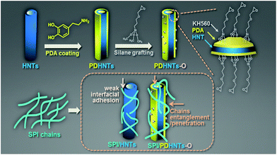 | ||
| Scheme 1 A schematic representation of the proposed surface chemistry of the PDA coating and KH560 silane grafting, and the SPI chains penetration and entanglement to the HNTs. | ||
2 Experimental
2.1 Materials
SPI (95% protein) was purchased from Yuwang Ecological Food Industry Company. HNTs were acquired from Lingshou County, Hebei Province, China. Dopamine (97% purity) and tris(hydroxymethyl aminomethane) (Tris) were purchased from Tianjin Heowns Biochem Company. γ-(2,3-Epoxypropoxy)propytrimethoxysilane (KH560) was obtained from Beijing Chemical Works. Glycerol (99% purity) and other chemical reagents of analytical reagent grade were purchased from Beijing Chemical Reagents Company. All chemicals were used without further purification.2.2 Surface modification of the HNTs by PDA coating and silane grafting
The HNTs were purified by dispersal into acetone under vigorous stirring at 30 °C for 5 h to remove the quartz impurities, followed by 12 h of drying at 110 °C and thorough grinding. The PDHNTs were obtained simply by immersing the HNTs (2.0 g) into dopamine (1.0 g L−1) and Tris–HCl (10 mM, 500 mL) buffer solution (pH 8.5) and gently stirring the mixture at 30 °C for 5 h. The resulting freeze-dried dark brown powder was obtained after three cycles of pump-filtration and rinsing with distilled water.22 The silane grafting of HNTs and PDHNTs followed two different methods established by previous researchers.22,26 The KH560-modified HNTs (HNTs-O) were prepared by adding HNTs (2 g) and ethanol/water (95![[thin space (1/6-em)]](https://www.rsc.org/images/entities/char_2009.gif) :
:![[thin space (1/6-em)]](https://www.rsc.org/images/entities/char_2009.gif) 5, v/v) into a 250 mL three-necked round bottom flask equipped with a condenser and adjusting the solution pH to 4.0 using acetic acid (20%, w/w) under magnetic stirring. Then, KH560 (2 g) was added dropwise into the mixture, and the solution was refluxed at 80 °C for 20 h. To prepare the KH560 grafted PDHNTs (PDHNTs-O), PDHNTs (2 g) and distilled water (100 g) were added into a 250 mL beaker and gently stirred at 60 °C for 20 h, and KH560 (2 g) was added dropwise. After cooling to room temperature, the precipitated HNTs-O or PDHNTs-O powders were pump-filtered and rinsed three times with ethanol/water (95
5, v/v) into a 250 mL three-necked round bottom flask equipped with a condenser and adjusting the solution pH to 4.0 using acetic acid (20%, w/w) under magnetic stirring. Then, KH560 (2 g) was added dropwise into the mixture, and the solution was refluxed at 80 °C for 20 h. To prepare the KH560 grafted PDHNTs (PDHNTs-O), PDHNTs (2 g) and distilled water (100 g) were added into a 250 mL beaker and gently stirred at 60 °C for 20 h, and KH560 (2 g) was added dropwise. After cooling to room temperature, the precipitated HNTs-O or PDHNTs-O powders were pump-filtered and rinsed three times with ethanol/water (95![[thin space (1/6-em)]](https://www.rsc.org/images/entities/char_2009.gif) :
:![[thin space (1/6-em)]](https://www.rsc.org/images/entities/char_2009.gif) 5) mixture or distilled water, respectively. The samples were dried at 100 °C for 24 h prior to further use.
5) mixture or distilled water, respectively. The samples were dried at 100 °C for 24 h prior to further use.
2.3 Preparation of the halloysite/SPI nanocomposite films
The experimental films were prepared using a two-step casting method.7 The SPI-based film solution was first prepared by sequentially adding SPI (5 g), glycerol (2.5 g), and distilled water (95 g) into a 250 mL beaker and adjusting its pH to 9.0 ± 0.1 with NaOH solution (5 M) and heating it to 85 °C for 30 min. The halloysite/SPI nanocomposite solutions were obtained by adding the formulated HNTs samples (Table 1) under magnetic stirring. Next, the solutions were treated with ultrasound for 5 min, poured into Teflon-coated plates and then vacuum dried at 45 °C for 24 h. The prepared films were placed into a 50% ± 2% relative humidity (RH) desiccator (regulated by saturated K2CO3) at room temperature for further analysis.2.4 Characterization
The microstructural changes of the HNTs samples (referring to the HNTs, HNTs-O, PDHNT and PDHNTs-O) were determined by Fourier transform infrared spectroscopy (FTIR, Nicolet 6700) and the halloysite/SPI nanocomposite films were observed by attenuated total reflectance-FTIR (ATR-FTIR, Nicolet 6700), both of which were conducted in a wavelength range of 650 to 3900 cm−1 under a total of 32 scans; ATR advanced correction in the OMNIC software was applied to rectify the FTIR spectra.X-ray photoelectron spectroscopy (XPS, ESCALAB250) was carried out using a monochromatic Al Kα source. The spectra were collected with a pass energy of 50 eV in increments of 0.1 eV.
X-ray diffraction (XRD, Bruker D8) was employed to investigate the crystalline properties of the halloysite/SPI nanocomposite films (powder state) using a Cu Kα radiation source (λ = 0.154 nm) and a theta scan ranging from 5° to 60° at 0.02° intervals. The diffraction data were analyzed in a Jade 5.0 software. The relative crystallinity index was calculated directly using the instrument with eqn (1).7
 | (1) |
Thermogravimetric analysis (TGA, Q50) was used to analyze the thermal properties of the HNTs samples and halloysite/SPI nanocomposite films over the temperature range of 100 °C to 800 °C and 60 °C to 600 °C, respectively. The heating rate was 10 °C min−1 under N2 atmosphere (100 mL min−1).
Transmission electron microscopy (TEM, JEM-2100F) was conducted at an acceleration voltage of 80 kV. For sampling, a small drop of the diluted colloidal solution of the HNTs samples in ethanol was initially deposited onto a piece of carbon-coated copper grid and dried at room temperature prior to imaging.
Field emission scanning electron microscopy (FE-SEM, Hitachi SU8010) was used to observe the surface fracture morphologies of the halloysite/SPI nanocomposite films at an accelerating voltage of 10 kV. The samples were sputtered with a 10 mm gold layer before observation to prevent electron beam charging.
The mechanical properties of halloysite/SPI nanocomposite films were determined on a tensile machine (WDW-02) at a loading speed at 50 mm min−1 and initial gauge length of 50 mm. Each sample (10 × 80 mm2) was tested in five replicate measurements.
The water resistance of the halloysite/SPI nanocomposite films was determined by calculating the moisture content (MC) and moisture absorption (MA) of the samples (20 × 20 mm2) using eqn (2) and (3).7,11 The reported values are the averages of five replicate measurements.
 | (2) |
 | (3) |
3 Results and discussion
3.1 The surface composition of the HNTs samples and the microstructural variation of halloysite/SPI nanocomposite films
The surface compositions of HNTs samples were determined by comparing the XPS spectra of the nanotube surfaces. Fig. 1 shows the low-resolution XPS wide scan spectra of the HNTs samples (Fig. 1A and B) and the C 1s core-level spectra of the PDHNTs (Fig. 1C) and PDHNTs-O (Fig. 1D), respectively. The characteristic elements of HNTs including O 1s, Si 2p/2s, and Al 2p/2s are attributable to the elements O, Si, and Al. The N 1s peak in the PDHNTs and PDHNTs-O spectra correspond to the N elements, suggesting the successful surface coating of the PDA ad-layer.29 In the HNTs and HNTs-O samples, carbon (C 1s peak in Fig. 1A) was observed on the mineral surfaces, which could be attributed to surface contamination on the oxide surface originating from the atmosphere or during the wet process.19 The C 1s core-level spectrum of the PDHNTs was curved-fitted to four peak components containing binding energy (BE) at 284.1 eV for C–C species, at 284.9 eV for C–N species, at 285.7 eV for C–O species, and at 287.4 eV for C![[double bond, length as m-dash]](https://www.rsc.org/images/entities/char_e001.gif) O species.19 After silane grafting onto the PDHNTs surface, the C 1s core-level spectrum of the PDHNTs-O was curved-fitted to more peak components with a BE peak at 283.1 eV corresponding to the C–Si species. The intensity of the C–O curve-fit spectrum was enhanced due to the increase in the C–O bonds per KH560 grafted PDA repeating unit, as illustrated in Scheme 2.22 These changes suggest the successful introduction of KH560 onto the PDA-coated HNTs surfaces.
O species.19 After silane grafting onto the PDHNTs surface, the C 1s core-level spectrum of the PDHNTs-O was curved-fitted to more peak components with a BE peak at 283.1 eV corresponding to the C–Si species. The intensity of the C–O curve-fit spectrum was enhanced due to the increase in the C–O bonds per KH560 grafted PDA repeating unit, as illustrated in Scheme 2.22 These changes suggest the successful introduction of KH560 onto the PDA-coated HNTs surfaces.
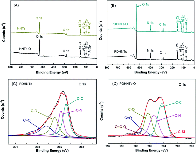 | ||
| Fig. 1 The XPS wide-scan spectra of (A) HNTs, HNTs-O and (B) PDHNTs, PDHNTs-O; the C 1s core-level spectra of (C) PDHNTs, and (D) PDHNTs-O. | ||
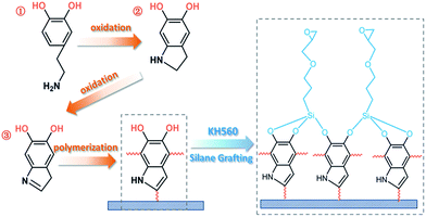 | ||
| Scheme 2 The proposed polymerization mechanism of dopamine polymerization and the possible chemical reactions of silane grafting. | ||
FTIR analysis confirmed the successful PDA coating and silane grafting on the HNTs surfaces in the mild infrared region (3900–650 cm−1) (Fig. 2A and B). In the HNTs, inner-surface and inner AlO–H stretching were observed at 3698 cm−1 and 3625 cm−1 as well as in-plane Si–O stretching at 1091 cm−1 and 1031 cm−1, symmetric stretching of Si–O–Si at 793 cm−1, and perpendicular stretching of Si–O–Al at 757 cm−1.16,19 After the silane grafting step, the HNTs characteristic peaks were fairly well-retained. The new peaks at 2940 cm−1 and 2875 cm−1 that appeared in the HNTs-O and PDHNTs-O samples were attributed to –CH2 non-symmetric/symmetric stretching vibrations, which proved the functionalization of the KH560 agents onto the nanotube surfaces (inset Fig. 2A).17 A relatively weak band at 1650 cm−1 appeared in the PDHNTs and PDHNTs-O samples, which were attributed to aromatic C![[double bond, length as m-dash]](https://www.rsc.org/images/entities/char_e001.gif) C stretching vibrations.22 The PDA/KH560 reagents appeared to bond on the inner AlOH group surfaces or to the AlOH/SiOH groups at the edges or external surfaces, as-evidenced by the broadened peaks at 1112 cm−1 and 1091 cm−1 corresponding to Si–O–Al and Si–O–Si groups, respectively, in comparison to the unmodified HNTs (Fig. 2B).30 The polymerization of PDA and the grafting of KH560 were successfully produced by chemical reactions on the HNTs surfaces in accordance with the XPS analysis.22,28
C stretching vibrations.22 The PDA/KH560 reagents appeared to bond on the inner AlOH group surfaces or to the AlOH/SiOH groups at the edges or external surfaces, as-evidenced by the broadened peaks at 1112 cm−1 and 1091 cm−1 corresponding to Si–O–Al and Si–O–Si groups, respectively, in comparison to the unmodified HNTs (Fig. 2B).30 The polymerization of PDA and the grafting of KH560 were successfully produced by chemical reactions on the HNTs surfaces in accordance with the XPS analysis.22,28
The chemical structure variations of the halloysite/SPI nanocomposite films were determined according to the ATR-FTIR spectra. Typical amide bands at 1645 cm−1, 1541 cm−1, and 1231 cm−1 were attributed to amide I (C![[double bond, length as m-dash]](https://www.rsc.org/images/entities/char_e001.gif) O stretching), amide II (N–H bending), and amide III (C–N and N–H stretching), respectively. The O–H/N–H bending vibration at 3298 cm−1 and –CH2 group stretching peaks at 2935 cm−1 and 2882 cm−1 were also observed.11,12
O stretching), amide II (N–H bending), and amide III (C–N and N–H stretching), respectively. The O–H/N–H bending vibration at 3298 cm−1 and –CH2 group stretching peaks at 2935 cm−1 and 2882 cm−1 were also observed.11,12
The adherent PDA layers can be effectively dip-coated onto a wide array of materials using a dopamine solution.24 The suspended active groups (quinone, –NH2/–OH groups) after catechol oxidization can also generate Michael addition or Schiff base reactions with the SPI chains.22 The intensities of the broad overlapped band at 3298 cm−1 in the free and bound O–H/N–H groups decreased compared to those of the unmodified SPI film, confirming the successful combination of SPI side chains with HNTs. The peak at 1031 cm−1 attributed to Si–O stretching was sharpened in the halloysite/SPI nanocomposite films, which further verifies the presence of the HNTs.
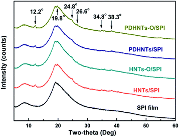
The XRD analysis results demonstrate the structural conformations of the halloysite/SPI nanocomposite films (Fig. 3). Compared to the SPI film, new peaks at 2θ values for the HNTs/SPI nanocomposite films at 12.2°, 19.8°, 24.8°, 26.6°, 34.8°, and 38.3° were revealed and referred to the characteristic peaks of the HNTs. The α-helix and β-sheet structures of the SPI secondary conformation can be ascribed to the broad peaks at 2θ = 8.4° and 19.2°, respectively. There were intensity reductions at 2θ = 8.4° after incorporating the HNTs in the samples, likely due to discontinuous nanotubes filling the SPI matrix.11
The calculated degrees of crystallinity of the SPI and halloysite/SPI nanocomposite films according to eqn (1) are listed in Table 2. It can be seen that the degree of crystallinity increased upon the addition of the HNTs (HNTs, HNTs-O, PDHNTs and PDHNTs-O) compared to that of the pristine SPI film, which was probably a result from the blending of the highly crystalline nanotubes and the SPI chains partially penetrating into the nanotubes with an orderly alignment.31 Higher crystallinities were observed in PDHNTs/SPI and PDHNTs-O/SPI films compared to the HNTs/SPI and HNTs-O/SPI films. Moreover, different tendencies in the degree of crystallinity after the silane grafting step in the samples with and without the PDA coating were observed. This was probably because the PDA ad-layer contributes to the active functionalization of the internal/external nanotube surfaces and thus promotes the uniform dispersion of PDHNTs-O and the SPI chains orderly alignment.
| Entry | SPI | HNTs/SPI | HNTs-O/SPI | PDHNTs/SPI | PDHNTs-O/SPI |
|---|---|---|---|---|---|
| Degree of crystallinity (%) | 27.9 | 32.1 | 31.0 | 32.2 | 33.4 |
| Entry | Tmax1a (°C) | ML1b (%) | Tmax2 (°C) | ML2 (%) | Mrc (%) |
|---|---|---|---|---|---|
| a Temperature of the maximum degradation rate.b Weight loss percentage during the degradation stage.c The residue weight at 800 °C. | |||||
| HNTs | 501.7 | 13.2 | 656.1 | 1.6 | 85.2 |
| HNTs-O | 496.4 | 14.4 | — | 1.1 | 84.5 |
| PDHNTs | 495.1 | 14.3 | 635.2 | 1.8 | 83.9 |
| PDHNTs-O | 494.1 | 16.1 | — | 1.5 | 82.4 |
| SPI film | 166.3 | 11.9 | 304.9 | 64.7 | 23.4 |
| HNTs/SPI | 171.3 | 11.3 | 305.9 | 63.1 | 25.6 |
| HNTs-O/SPI | 172.1 | 10.9 | 304.6 | 64.1 | 25.0 |
| PDHNTs/SPI | — | 10.3 | 303.4 | 64.2 | 25.5 |
| PDHNTs-O/SPI | — | 10.2 | 303.7 | 63.7 | 26.1 |
3.2 The thermal performance of the HNTs samples and halloysite/SPI nanocomposite films
Fig. 4A shows the weight loss traces and derivative TG (DTG) curves of the HNTs samples before and after surface modification between 100 °C and 800 °C. The weight loss from 200.0 °C to 300.0 °C was attributed to the evaporation of the interlayer water molecules.16 The main decomposition stage (ML1) of the HNTs was resolved at 461.2–527.3 °C with a DTG peak at 501.7 °C due to the dehydroxylation of the residual structural AlOH groups. In this stage, the crystalline structure of the HNTs was destroyed and a 13.2% weight loss was observed (Table 3).19 For the modified HNTs samples, the mass loss from 200.0 °C to 461.2 °C (before the ML1 stage) corresponds to both bound water molecule evaporation and the breakdown of the cross-linked surface framework created by the PDA coating and/or silane grafting. This stage progressed gradually and partially overlapped with other stages. Sun et al. have made similar observations.32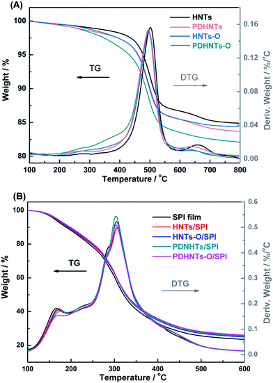 | ||
| Fig. 4 The TG and DTG curves obtained for (A) HNTs, HNTs-O, PDHNTs and PDHNTs-O and (B) the SPI, HNTs/SPI, HNTs-O/SPI, PDHNTs/SPI and PDHNTs-O/SPI films. | ||
After 527.3 °C, a further degradation stage (ML2) appeared and the weight losses of HNTs-O and PDHNTs-O (1.1% and 1.5%) were less than that of HNTs or PDHNTs at 1.6% and 1.8%, respectively. This was likely related to the formation of SiO2 residues during the thermal degradation of KH560. The residual weights of the HNTs samples fall in the order of: HNTs > HNTs-O > PDHNTs > PDHNTs-O because the weight losses of the modified HNTs also include the thermal decomposition of some oligomers and pendant groups of the PDA/KH560 reagents after surface modification.17,19
The weight loss traces and DTG curves of the halloysite/SPI nanocomposite films presented similar thermal behavior to that of the unmodified SPI film (Fig. 4B). There were two main degradation stages exclusive of the dehydration reaction (before 120 °C): glycerol degradation from 120 °C to 250 °C and protein backbone decomposition at 250–400 °C.7,11 During the initial stage, glycerol degradation was slower in the halloysite/SPI nanocomposite films because the nanotubes impeded the escape of volatile products by barrier and entrapment effects. The dispersity of the halloysites also were likely to complicate the pathways, hindering small molecule decomposition.17 Accordingly, we hypothesize that the PDHNTs and PDHNTs-O samples were dispersed more uniformly than others and had a favorable interfacial combination with the SPI matrix.
3.3 Micromorphological analysis of the HNTs samples and the halloysite/SPI nanocomposite films
The structure and morphology of the HNTs samples before and after surface modification were investigated by TEM, as shown in Fig. 5. The halloysite nanotubes are cylindrical in shape and contain a clear inner lumen space running longitudinally along the cylinder, reflecting the double-layered and open-ended characteristics.19 The HNTs samples showed a relatively uniform morphology in the tubule quality, but had irregular dimensions – an external diameter of 40–65 nm and inner diameter of 19–32 nm – within which the SPI chains are assumed to penetrate into the nanotubes30 (the accuracy of these dimensions is limited by the number of particles observed in the TEM images). Concentric structures were observed in some of the halloysite particles (Fig. 5a and d) within which the tubular subunits were concentrically arranged in a telescope-like form.16 After the PDA coating, the lumen space became fairly hazy in the center and both the inner lumens and outer surfaces of the PDHNTs and PDHNTs-O samples were filled or coated with some gas-like padding (Fig. 5c and d). This is likely attributable to the self-polymerized PDA layer.33 Compared to the HNTs, the HNTs-O had relatively well retained the lumen spaces, but the nanotube edges and surfaces became jagged due to the silane grafting of KH560 onto the HNTs surfaces.Fig. 6 shows the fracture morphologies of the SPI film and halloysite/SPI nanocomposite films observed via FE-SEM. The SPI chains were self-aggregated and formed a relatively compact network during the drying process after heat treatment unfolded the peptide chains. The fracture surface of the unmodified SPI film was relatively smooth and even, as shown in Fig. 6a, with some river-pattern cleavages. As opposed to the SPI film, the fracture cleavages in the halloysite/SPI nanocomposite films were vertically oriented and less distinct. In theory, the presence of the HNTs samples in the polymeric matrix transforms the reinforcing mechanism towards the energy absorption mechanism of zone shielding mechanism or matrix shear yielding mechanism due to the formation of micro-voids or micro-cracks around the crack tips, which inhibit the crack growth.34 However, the difficulty in obtaining well-dispersed nano-material fractions impacts the nanocomposites' properties.13 As shown in Fig. 6b–d, the white points speculated to be the HNTs samples together with its agglomerates were relatively uniformly spread across the SPI matrix. The magnified inset SEM images further detail this interfacial combination. As shown in Fig. 6b and c, the HNTs and HNT-Os were stripped from the matrix thus impeding the load transfer from the polymeric matrix to the nanotubes. This ultimately weakens the material's mechanical properties. In contrast, the surface coating of PDA and KH560 grafting functionalized the internal/external surfaces, thus immobilizing the penetrated SPI chains and benefiting the external adhesion of the PDHNTs-O to the SPI matrix on the basis of the reduced phenomena of semi-stripped PDHNTs-O (inset of Fig. 6d). The PDHNTs-O samples contained multiple interfacial bonding sites to combine with the peptide chains. The SPI chain penetrations and entanglements facilitate the effective bi-phase combination in the PDHNTs-O/SPI films corresponding to an increase in the TS.
 | ||
| Fig. 6 FE-SEM images of the (a) unmodified SPI film, (b) HNTs/SPI film, (c) HNTs-O/SPI film and (d) PDHNTs-O/SPI film. | ||
3.4 The mechanical properties of the halloysite/SPI nanocomposite films
The contribution of the HNTs to the mechanical properties, including the tensile strength (TS), elongation at break (EB), and Young's modulus of the SPI-based films are shown in Fig. 7. Both the TS and Young's modulus of the halloysite/SPI nanocomposite films were reinforced, while the films' toughness fluctuated due to a slight variation in the EB value of the PDHNTs-O/SPI film. Both the dispersion and interfacial combination of the nanoparticles to the polymeric matrix influenced the films' mechanical properties.13 After incorporating PDHNTs-O, the film's TS value increased from 5.90 MPa to a maximum of 8.73 MPa. As shown in Fig. 7B, the EB values of the halloysite/SPI nanocomposite films gradually decreased, while the PDHNTs-O/SPI films became a little more flexible with a slight increase in the EB value. This was attributed to the improved distribution of the PDHNTs-O and followed the shear yielding mechanism that acted on the crack tips to reduce the stress concentration and crack propagation, which altogether toughened the polymeric SPI matrix.34 The Young's modulus of the halloysite/SPI nanocomposite films, based on the slope calculations of the obtained stress–strain curves, markedly increased compared to the control and the Young's modulus of the PDHNTs-O/SPI film increasing from 104.4 MPa to 161.3 MPa (a 54.5% increase). Therefore, the surface functionalized PDHNTs-O and its uniform dispersal apparently strengthened the cross-linked framework and transferred the impulsive force across the nanocomposite film. | ||
| Fig. 7 The mechanical properties of (A) TS, (B) EB, and (C) the Young's modulus of SPI and halloysite/SPI nanocomposite films. | ||
3.5 The water resistance and surface hydrophobicity of the halloysite/SPI nanocomposite films
The films' water resistance characteristics were determined by measuring their respective moisture uptake at various humidities. The MC and MA values of the halloysite/SPI nanocomposite films are shown in Fig. 8. The MC values of the different halloysite/SPI nanocomposite films were nearly identical; Xu et al. have made similar observations.7 The incorporation of the HNTs, HNTs-O, PDHNTs and PDHNTs-O decreased the films' MA values from 87.3% in the control to 80.9%, 79.4%, 61.1%, and 59.4%, respectively. The significant decrease in MA in the PDHNTs/SPI and PDHNTs-O/SPI films may be attributed to the nanotube inner immobilization and active interfacial bonding to the SPI matrix, in accordance with the TEM images featuring jagged nanotube internal/external surfaces. In addition, as water evaporated from the material, the polar groups were more easily exposed to the edges of the film (i.e., the films were water-sensitive).35 The filling of the HNTs samples, particularly the surface functionalized PDHNTs-O, consumed certain polar amine acids (e.g., glutamine, lysine) upon chemical reaction and thus, formed less penetrable outermost surfaces that partially prevented moisture invasion.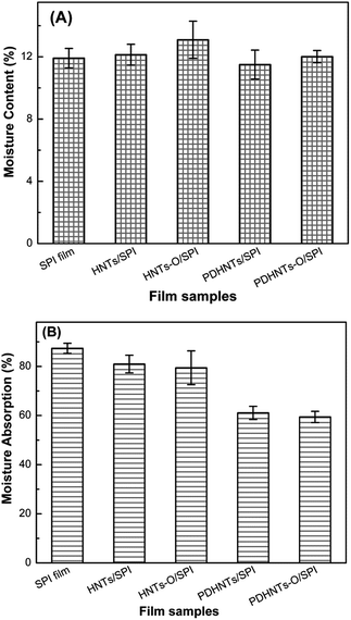 | ||
| Fig. 8 (A) The moisture content and (B) moisture absorption of SPI and the halloysite/SPI nanocomposite films. | ||
4 Conclusions
A facile surface modification of the internal/external HNTs surfaces was performed using the bio-inspired dopamine self-polymerization and functional silane grafting. PDHNTs-O nanotubes were surrounded by PDA layers on both sides after the proposed treatment, while epoxy groups were anchored onto the PDA layer via the silane grafting of KH560. The active and functional surfaces of PDHNTs-O showed superb interfacial adhesions with the penetrated and entangled SPI chains. As a result, the tensile strength and Young's modulus of the SPI/PDHNTs-O films were significantly improved from 5.90 MPa to 8.73 MPa and from 104.4 MPa to 161.3 MPa, respectively. The functional surfaces featuring dense reaction sites further enhanced the films' water resistance with a 47.1% decrease in moisture absorption. In summary, this study demonstrates a facile and efficient approach for natural HNTs functionalization with enhanced luminal/interfacial adhesion to fabricate high-performance bio-nanocomposite films.Acknowledgements
This research was supported by the Fundamental Research Funds for the Central Universities (2016ZCQ01).Notes and references
- P. Gupta and K. K. Nayak, Polym. Eng. Sci., 2015, 55, 485–498 CAS
.
- R. R. Koshy, S. K. Mary, S. Thomas and L. A. Pothan, Food Hydrocolloids, 2015, 50, 174–192 CrossRef CAS
.
- F. Bernsmann, V. Ball, F. Addiego, A. Ponche, M. Michel, J. J. Gracio, V. Toniazzo and D. Ruch, Langmuir, 2011, 27, 2819–2825 CrossRef CAS PubMed
.
- K. B. Chien and R. N. Shah, Acta Biomater., 2012, 8, 694–703 CrossRef CAS PubMed
.
- A. González, M. C. Strumia and C. I. Alvarez Igarzabal, J. Food Eng., 2011, 106, 331–338 CrossRef
.
- F. Song, D. L. Tang, X. L. Wang and Y. Z. Wang, Biomacromolecules, 2011, 12, 3369–3380 CrossRef CAS PubMed
.
- F. Xu, W. Zhang, S. Zhang, L. Li, J. Li and Y. Zhang, J. Appl. Polym. Sci., 2015, 132, 42578 Search PubMed
.
- E. Klüver and M. Meyer, Polym. Eng. Sci., 2015, 55, 1912–1919 Search PubMed
.
- L. Ma, Y. Yang, J. Yao, Z. Shao and X. Chen, Polym. Chem., 2013, 4, 5425–5431 RSC
.
- S. Wang, B. Zhu, D. Li, X. Fu and L. Shi, Mater. Lett., 2012, 83, 42–45 CrossRef CAS
.
- Y. Li, H. Chen, Y. Dong, K. Li, L. Li and J. Li, Ind. Crops Prod., 2016, 82, 133–140 CrossRef CAS
.
- B. J. Kim, S. Kim, D. X. Oh, A. Masic, H. J. Cha and D. S. Hwang, J. Mater. Chem. B, 2015, 3, 112–118 RSC
.
- P. Podsiadlo, A. K. Kaushik, E. M. Arruda, A. M. Waas, B. S. Shim, J. Xu, H. Nandivada, B. G. Pumplin, J. Lahann and A. Ramamoorthy, Science, 2007, 318, 80–83 CrossRef CAS PubMed
.
- Y. Lvov and E. Abdullayev, Prog. Polym. Sci., 2013, 38, 1690–1719 CrossRef CAS
.
- B. Fei, B. Qian, Z. Yang, R. Wang, W. C. Liu, C. L. Mak and J. H. Xin, Carbon, 2008, 46, 1795–1797 CrossRef CAS
.
- P. Yuan, P. D. Southon, Z. Liu, M. E. R. Green, J. M. Hook, S. J. Antill and C. J. Kepert, J. Phys. Chem. C, 2008, 112, 15742–15751 CAS
.
- S. Zhang, C. Xia, Y. Dong, Y. Yan, J. Li, S. Q. Shi and L. Cai, Ind. Crops Prod., 2016, 80, 207–213 CrossRef CAS
.
- P. Sun, G. Liu, D. Lv, X. Dong, J. Wu and D. Wang, RSC Adv., 2015, 5, 52916–52925 RSC
.
- V. S. Raman, S. Rooj, A. Das, K. W. Stöckelhuber, F. Simon, G. B. Nando and G. Heinrich, J. Macromol. Sci., Part A: Pure Appl. Chem., 2013, 50, 1091–1106 CrossRef CAS
.
- Y. Guo, S. He, K. Yang, Y. Xue, X. Zuo, Y. Yu, Y. Liu, C.-C. Chang and M. H. Rafailovich, ACS Appl. Mater. Interfaces, 2016, 8, 17565–17573 CAS
.
- W. Lee, J. U. Lee and J.-H. Byun, Compos. Sci. Technol., 2015, 110, 53–61 CrossRef CAS
.
- R. Sa, Y. Yan, Z. Wei, L. Zhang, W. Wang and M. Tian, ACS Appl. Mater. Interfaces, 2014, 6, 21730–21738 CAS
.
- L. Wang, M. Xiao, S. Dai, J. Song, X. Ni, Y. Fang, H. Corke and F. Jiang, Carbohydr. Polym., 2014, 101, 136–145 CrossRef CAS PubMed
.
- H. Lee, S. M. Dellatore, W. M. Miller and P. B. Messersmith, Science, 2007, 318, 426–430 CrossRef CAS PubMed
.
- S. M. Kang, J. Rho, I. S. Choi, P. B. Messersmith and H. Lee, J. Am. Chem. Soc., 2009, 131, 13224–13225 CrossRef CAS PubMed
.
- J. Wu, L. Zhang, Y. Wang, Y. Long, H. Gao, X. Zhang, N. Zhao, Y. Cai and J. Xu, Langmuir, 2011, 27, 13684–13691 CrossRef CAS PubMed
.
- J. H. Ryu, S. Hong and H. Lee, Acta Biomater., 2015, 27, 101–115 CrossRef CAS PubMed
.
- J. Lee, M. Yoon, E. Lee, D. Lim and K. Kim, Macromol. Res., 2014, 22, 738–745 CrossRef CAS
.
- R. Sa, Z. Wei, Y. Yan, L. Wang, W. Wang, L. Zhang, N. Ning and M. Tian, Compos. Sci. Technol., 2015, 113, 54–62 CrossRef CAS
.
- L. N. Carli, T. S. Daitx, G. V. Soares, J. S. Crespo and R. S. Mauler, Appl. Clay Sci., 2014, 87, 311–319 CrossRef CAS
.
- H. Zheng, F. Ai, M. Wei, J. Huang and P. R. Chang, Macromol. Mater. Eng., 2007, 292, 780–788 CrossRef CAS
.
- P. Sun, G. Liu, D. Lv, X. Dong, J. Wu and D. Wang, J. Appl. Polym. Sci., 2016, 133, 43249 Search PubMed
.
- W. O. Yah, H. Xu, H. Soejima, W. Ma, Y. Lvov and A. Takahara, J. Am. Chem. Soc., 2012, 134, 12134–12137 CrossRef CAS PubMed
.
- M. T. Albdiry and B. F. Yousif, Mater. Des., 2014, 57, 279–288 CrossRef CAS
.
- Y. Li, F. Chen, L. Zhang and Y. Yao, Mater. Lett., 2015, 149, 120–122 CrossRef CAS
.
| This journal is © The Royal Society of Chemistry 2017 |


