 Open Access Article
Creative Commons Attribution 3.0 Unported Licence
Enhanced light scattering effect of wrinkled transparent conductive ITO thin film
Chuang Wang†
ad,
Haoran Zhang† ad,
Fengyou Yangad,
Yongtao Fanc and
Qian Liu*abd
aCAS Center for Excellence in Nanoscience, National Center for Nanoscience and Technology, Beijing 100190, P. R. China. E-mail: liuq@nanoctr.cn
bThe MOE Key Laboratory of Weak-Light Nonlinear Photonics, TEDA Applied Physics Institute and School of Physics, Nankai University, Tianjin 300457, P. R. China
cShanghai Institute of Optics and Fine Mechanics, Chinese Academy of Sciences, Shanghai 201800, P. R. China
dUniversity of Chinese Academy of Sciences, Beijing 100049, P. R. China
First published on 12th May 2017
Abstract
Indium tin oxide (ITO) plays an important role due to its high transparency and high conductivity in various optoelectronic thin-film devices. However, ITO has the drawback of mechanical fragility, limiting its development. Wrinkling has been considered a powerful tool for improving the flexibility and surface properties of thin films, but wrinkled ITO has not been reported so far. In this work, we fabricate uniform wrinkles on ITO and systematically study the properties of the wrinkled ITO in optics, electrics and mechanics. The wrinkled ITO shows a high optical transmittance and also a high haze value due to a remarkable wrinkle-induced enhancement of light scattering, which is beneficial for solar cells and light-emitting diodes. Our experimental results also indicate that wrinkles can effectively improve the mechanical bending performance of ITO without compromising the crystallization and electrical conductivity.
Introduction
Wrinkling, a ubiquitous natural phenomenon, occurs spontaneously when a multilayer thin-film system is under compressive stress. Previously, wrinkles have always been regarded as having a negative effect on thin-film devices. Once they appear on the surface, it usually means that some damage has been caused. But in recent years, some studies have found that wrinkle structures are also helpful for improving the surface or interface properties of thin-film devices.1–8 For example, wrinkles can enhance the luminous efficiency of organic light emitting diodes (OLEDs)3 and increase the energy harvesting efficiency of solar cells.4 Moreover, in stretchable optoelectronic devices, wrinkles can release stress and increase integral flexibility.2 Besides, wrinkled structures also play an important role in many other fields such as microfluidics,8 mechanical metrology,9 strain-engineering10,11 and so on.In various optoelectronic devices such as OLEDs and solar cells, materials with a remarkable combination of high electrical conductivity and optical transparency are indispensable.12 Numerous materials have been exploited for transparent conductive electrodes (TCEs), including: (1) doped metal oxide films13–15 such as indium tin oxide (ITO), fluorine-doped tin oxide (FTO), aluminum-doped zinc oxide (AZO) and indium-doped zinc oxide (IZO); (2) transparent conductive polymer materials,16 for example poly(3,4-ethylenedioxythiophene):poly(styrenesulfonate) (PEDOT:PSS); (3) network-type thin films of noble metal (gold or silver) nanowires17–19 or carbon nanotubes;20 (4) graphene21 and other two-dimensional materials. Among them, ITO is the most preferred material of the past several decades because of its mature technique and excellent performance.12–14 However, the one critical drawback of ITO is that it easily cracks at very low bending strain, which limits its applications in flexible devices. Introducing wrinkle structures might be an effective strategy to improve the flexibility of ITO films and enhance other surface properties as well.
To the best of our knowledge, there is no report on studying the introduction of wrinkles into ITO for enhancing its surface performance. In this work, we fabricate random wrinkles on ITO films in a simple and low-cost way and comprehensively study the influence of the wrinkles on ITO. The results indicate that the wrinkled ITO has a huge increase in light scattering and in bending resistance, while the optical transparency, crystal structure and electrical conductivity remain unaffected.
Experimental
Fabrication of wrinkled and flat ITO films
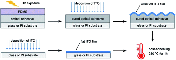
To fabricate high quality ITO films, various methods have been proposed, such as thermal evaporation, chemical vapor deposition (CVD), pulsed laser deposition (PLD) and magnetron sputtering. Among them, magnetron sputtering is the most used method because of its good uniformity and high efficiency. In this study, we deposited ITO films by a magnetron sputtering deposition system (Kurt J. Lesker, PVD75) equipped with a load-lock.The fabrication process for wrinkles in an ITO/adhesive bilayer on a glass or polyimide (PI) substrate is depicted in Fig. 1. Firstly, a few drops of Norland Optical Adhesive (NOA 61) were dripped onto a glass or PI substrate and covered with a flat PDMS stamp to form a flat and uniform optical adhesive film (about 20 μm thick). After being exposed to ultraviolet light for 10 min (365 nm, 200 mW cm−2), the PDMS stamp was removed, leaving a cured optical adhesive film which was ready for the deposition of ITO. The target was an In2O3–SnO2 (90![[thin space (1/6-em)]](https://www.rsc.org/images/entities/char_2009.gif) :
:![[thin space (1/6-em)]](https://www.rsc.org/images/entities/char_2009.gif) 10 wt%) ceramic bonded to a copper backing plate. The base pressure of the vacuum system before deposition was lower than 1 × 10⁻⁶ Torr to ensure the film quality. Then the ITO sputtering was performed in a pure argon (100% Ar) atmosphere at a pressure of 5 mTorr with a DC power of 60 W. The sputtering time was 1 h for depositing an ITO layer about 70 nm thick. During the deposition, the collision of target molecules with the NOA 61 layer can cause a local heating effect and impose isotropic compressive stress on the adhesive layer, resulting in the generation of random wrinkles on the ITO/NOA 61 bilayer. For reference, a flat ITO film was also deposited directly on a glass or PI substrate in the absence of NOA 61 according to the same sputtering process parameters. For increasing the electrical conductivity and light transmittance of the amorphous ITO films deposited, crystallization is needed by annealing the ITO at high temperature. Therefore, after deposition, both the wrinkled ITO/NOA 61 bilayer and flat ITO film were post-annealed in the same vacuum chamber at a temperature of 250 °C for 1 h for crystallization.
10 wt%) ceramic bonded to a copper backing plate. The base pressure of the vacuum system before deposition was lower than 1 × 10⁻⁶ Torr to ensure the film quality. Then the ITO sputtering was performed in a pure argon (100% Ar) atmosphere at a pressure of 5 mTorr with a DC power of 60 W. The sputtering time was 1 h for depositing an ITO layer about 70 nm thick. During the deposition, the collision of target molecules with the NOA 61 layer can cause a local heating effect and impose isotropic compressive stress on the adhesive layer, resulting in the generation of random wrinkles on the ITO/NOA 61 bilayer. For reference, a flat ITO film was also deposited directly on a glass or PI substrate in the absence of NOA 61 according to the same sputtering process parameters. For increasing the electrical conductivity and light transmittance of the amorphous ITO films deposited, crystallization is needed by annealing the ITO at high temperature. Therefore, after deposition, both the wrinkled ITO/NOA 61 bilayer and flat ITO film were post-annealed in the same vacuum chamber at a temperature of 250 °C for 1 h for crystallization.
Our fabrication method for wrinkles has the advantages of being a simple process and low cost, compared to methods that involve lithography or chemical synthesis for creating textured or grating structures.22
Characterizations
The surface morphologies were characterized by a laser scanning confocal microscope (LSCM, Olympus, LEXT-OLS4000) and a scanning electron microscope (SEM, Hitachi, S4800). The optical transmittance spectra of the films were recorded by a UV/VIS/NIR spectrophotometer (Varian, Cary 5000) at wavelengths from 400 to 800 nm. The total transmittance was measured by an integrating sphere to collect the transmitted light at all angles. The specular transmittance was measured by the photo-detector only to collect the light flux along the incident light axis. The thickness of the NOA 61 layer and the deposited ITO film were measured by a surface profiler (Veeco, Dektak 150). X-ray diffraction (XRD) was performed by an X-ray diffractometer (Bruker, D8 Focus) to determine the crystal structure and phase of ITO. The square resistance of the films was measured by a Keithley System SourceMeter (2602A) attached to a manual operation probe station (TiTan Power, ZFT-160-MT).Results and discussion
Surface morphology
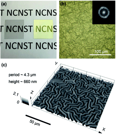
Fig. 2(a) shows the flat ITO film (left) and the wrinkled ITO/NOA 61 bilayer (right) on a glass substrate (size: 24 × 24 × 0.15 mm) after annealing. Obviously, both samples are transparent in visible light. From the optical microscope image and the corresponding Fast Fourier Transform (FFT) analysis in Fig. 2(b), we can observe that the ITO wrinkles exhibit random orientation and a uniform distribution. The wrinkles are periodical with an intrinsic wavelength, as shown in the inset of Fig. 2(b), which is determined by the modulus and thickness of the two layers, while the amplitude of the wrinkles depends on the bilayer system and the strain value.1 Here the wrinkle period is about 4.3 μm and the peak-to-valley height is about 660 nm, according to the three-dimensional morphologic characterization shown in Fig. 2(c). The periodicity and randomness of the ITO wrinkles are beneficial for both light extraction and harvesting. In addition, our wrinkled structure has a microscale period and a submicron height, offering a moderate aspect ratio of about 0.15, which is very suitable for the use of TCEs in optoelectronic devices. In principle, a too small aspect ratio will not benefit the surface performance enhancement, while a too big aspect ratio may also degrade the device efficiency because of the underfill and air gaps in the above spin-coated active layer.22Enhanced effect of light scattering
Optical properties are a key performance indicator of ITO films and crucially depend on the surface morphology. The flat ITO on a glass substrate is highly transparent and barely scatters the incident light, resulting in a specular transmission. The wrinkled ITO on a glass substrate is also transparent, but scatters a large part of the incident light, which leads to a diffuse transmission. In other words, all the light transmitted through the flat ITO is propagated along the incident direction, while most of the light that passes through the wrinkled ITO is deflected from the propagation path. Fig. 3(a) describes this distinction. The total transmittance of the flat ITO and the wrinkled ITO/NOA 61 measured with an integrating sphere is shown in Fig. 3(b). According to the data, the wrinkled sample even has a slightly higher optical transmittance (about 90%) than the flat one. This wrinkle-induced enhancement of optical transmission may be caused by the light-trapping at the valleys of the wrinkles. Besides the total transmittance, haze is also frequently used to quantify the percentage of scattered light in the total transmitted light. The haze is calculated as:23
 | (1) |
 | ||
| Fig. 3 (a) Schematic diagram showing specular transmission of flat ITO and diffuse transmission of wrinkled ITO/NOA 61. Total transmittance (b) and haze (c) of flat ITO and wrinkled ITO/NOA 61. | ||
Improvement of bending performance
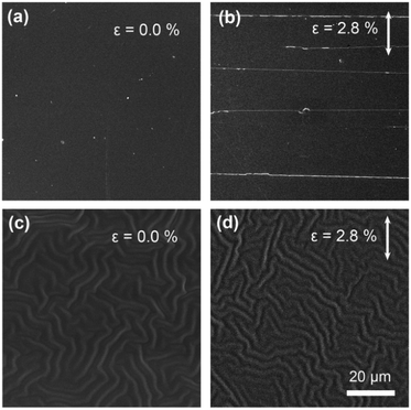
In addition to providing a huge increase in light scattering, wrinkles can also relieve mechanical stress and thus increase the robustness of devices.2,4 ITO is a kind of ceramic material and naturally has poor bending performance. Here we fabricated the flat ITO film and wrinkled ITO/NOA 61 bilayer on flexible PI substrates (size: 24 × 24 × 0.15 mm), and investigated their tolerance to mechanical bending. Bend tests for the flat and wrinkled ITO samples were performed with a pre-specified bending strain (ε), which is defined as:4
 | (2) |
Crystal structure and electrical conductivity
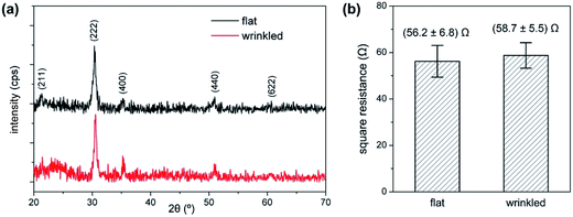
Whether the wrinkling process will affect the crystal structure and electrical properties of ITO is also an unavoidable issue that needs attention. The XRD spectra of our flat and wrinkled ITO films after being annealed at 250 °C for 1 h under vacuum are shown in Fig. 5(a). The cubic structure with diffraction peaks corresponding to the (2 1 1), (2 2 2), (4 0 0), (4 4 0) and (6 2 2) planes reflects that both annealed films have been crystallized.13,14 The intensity of some characteristic peaks is not very strong because the ITO thickness is relatively thin and the annealing temperature is moderate. From the XRD structural investigation, there is no evident difference between the flat and wrinkled ITO films in the crystalline structure, which indicates that the wrinkling process doesn’t affect the ITO crystallization during annealing. | ||
| Fig. 5 X-ray diffraction spectra (a) and square resistance (b) of flat and wrinkled ITO. Each set of data in (b) shows the average value and standard deviation of five identical samples. | ||
The degree of crystallization can significantly affect the properties of ITO, especially the electrical conductivity. When the film is amorphous, a large number of electrons are bound within a small range by the non-uniform structure and the defects. Once the ITO becomes crystalline, these bound electrons are released, consequently increasing the carrier concentration and the mobility of the ITO film. In our study, the flat and the wrinkled ITO films exhibit nearly equivalent electrical conductivity, as shown in Fig. 5(b), due to undergoing the same crystallization. It should be noted that the square resistance of the wrinkled ITO film is a little higher than that of the flat film, which may be attributed to the wrinkles slightly extending the surface area of the ITO film, but this subtle distinction won’t impact the actual use.
Conclusions
In summary, we have investigated the wrinkled transparent conductive ITO thin film, which is naturally formed when ITO is deposited on a layer of NOA 61. Experimental results indicate that the wrinkled ITO film exhibits not only ultrahigh transparency but also an ultrahigh haze value, which result from the wrinkle-enhanced light scattering enhancement effect. It should be specially pointed out that the light scattering enhancement effect will benefit the light harvesting efficiency of solar cells as well as the light extracting efficiency of LEDs. In addition, the wrinkles can also increase the flexibility of the ITO film and thus can improve the device stability and tolerance. Moreover, the wrinkled ITO films still maintain an unchanged light transparency, electrical resistance and crystal structure. These results indicate that the wrinkled ITO will have great potential applications in the fields of solar cells, LEDs and flexible devices. We believe that the work can also provide helpful guidance for increasing the performances of other transparent conductive films.Acknowledgements
This project is supported by the National Key Research Program of China (2016YFA0200403), the CAS Strategy Pilot Program (XDA 09020300), and the National Natural Science Foundation of China (10974037, 61405223).Notes and references
- S. Yang, K. Khare and P.-C. Lin, Adv. Funct. Mater., 2010, 20, 2550–2564 CrossRef CAS.
- Y. Sun, W. M. Choi, H. Jiang, Y. Y. Huang and J. A. Rogers, Nat. Nanotechnol., 2006, 1, 201–207 CrossRef CAS PubMed.
- J. Moon, E. Kim, S. K. Park, K. Lee, J.-W. Shin, D.-H. Cho, J. Lee, C. W. Joo, N. S. Cho, J.-H. Han, B.-G. Yu, S. Yoo and J.-I. Lee, Org. Electron., 2015, 26, 273–278 CrossRef CAS.
- J. B. Kim, P. Kim, N. C. Pégard, S. J. Oh, C. R. Kagan, J. W. Fleischer, H. A. Stone and Y.-L. Loo, Nat. Photonics, 2012, 6, 327–332 CrossRef CAS.
- C. F. Guo, V. Nayyar, Z. Zhang, Y. Chen, J. Miao, R. Huang and Q. Liu, Adv. Mater., 2012, 24, 3010–3014 CrossRef CAS PubMed.
- A. R. Shugurov, A. I. Kozelskaya and A. V. Panin, RSC Adv., 2014, 4, 7389 RSC.
- J. Yin and C. Lu, Soft Matter, 2012, 8, 6528 RSC.
- K. Khare, J. Zhou and S. Yang, Langmuir, 2009, 25, 12794–12799 CrossRef CAS PubMed.
- J. Y. Chung, A. J. Nolte and C. M. Stafford, Adv. Mater., 2011, 23, 349–368 CrossRef CAS PubMed.
- H. Zhang, F. Yang, J. Dong, L. Du, C. Wang, J. Zhang, C. F. Guo and Q. Liu, Nat. Commun., 2016, 7, 13743 CrossRef CAS PubMed.
- S. Yang, C. Wang, H. Sahin, H. Chen, Y. Li, S. S. Li, A. Suslu, F. M. Peeters, Q. Liu, J. Li and S. Tongay, Nano Lett., 2015, 15, 1660–1666 CrossRef CAS PubMed.
- A. Kumar and C. Zhou, ACS Nano, 2010, 4, 11–14 CrossRef CAS PubMed.
- H. Kim, C. M. Gilmore, A. Piqué, J. S. Horwitz, H. Mattoussi, H. Murata, Z. H. Kafafi and D. B. Chrisey, J. Appl. Phys., 1999, 86, 6451–6461 CrossRef CAS.
- C. C. Wu, C. I. Wu, J. C. Sturm and A. Kahn, Appl. Phys. Lett., 1997, 70, 1348–1350 CrossRef CAS.
- D. Liu, S. Ren, X. Ma, C. Liu, L. Wu, W. Li, J. Zhang and L. Feng, RSC Adv., 2017, 7, 8295–8302 RSC.
- Y. H. Kim, C. Sachse, M. L. Machala, C. May, L. Müller-Meskamp and K. Leo, Adv. Funct. Mater., 2011, 21, 1076–1081 CrossRef CAS.
- C. F. Guo, Q. Liu, G. Wang, Y. Wang, Z. Shi, Z. Suo, C.-W. Chu and Z. Ren, Proc. Natl. Acad. Sci. U. S. A., 2015, 112, 12332–12337 CrossRef CAS PubMed.
- C. F. Guo, T. Sun, Q. Liu, Z. Suo and Z. Ren, Nat. Commun., 2014, 5, 3121 Search PubMed.
- Y. Song, Y. Jiang, L. Shi, S. Cao, X. Feng, M. Miao and J. Fang, Nanoscale, 2015, 7, 13694–13701 RSC.
- Z. Wu, Z. Chen, X. Du, J. M. Logan, J. Sippel, M. Nikolou, K. Kamaras, J. R. Reynolds, D. B. Tanner and A. F. Hebard, Science, 2004, 305, 1273–1276 CrossRef CAS PubMed.
- X. Wang, L. Zhi and K. Müllen, Nano Lett., 2008, 8, 323–327 CrossRef CAS PubMed.
- K. S. Nalwa, J. M. Park, K. M. Ho and S. Chaudhary, Adv. Mater., 2011, 23, 112–116 CrossRef CAS PubMed.
- Z. Fang, H. Zhu, Y. Yuan, D. Ha, S. Zhu, C. Preston, Q. Chen, Y. Li, X. Han, S. Lee, G. Chen, T. Li, J. Munday, J. Huang and L. Hu, Nano Lett., 2014, 14, 765–773 CrossRef CAS PubMed.
Footnote |
| † These authors contributed equally to the work. |
| This journal is © The Royal Society of Chemistry 2017 |


