 Open Access Article
Creative Commons Attribution 3.0 Unported Licence
A general strategy for high performance stretchable conductors based on carbon nanotubes and silver nanowires
Lijun Cao,
Zhan Wang,
Yang Liu,
Rui Shi,
Xiangjing Wang and
Juqing Liu *
*
Key Laboratory of Flexible Electronics (KLOFE), Institute of Advanced Materials (IAM), Jiangsu National Synergistic Innovation Center for Advanced Materials (SICAM), Nanjing Tech University (NanjingTech), 30 South Puzhu Road, Nanjing 211816, P. R. China. E-mail: iamjqliu@njtech.edu.cn
First published on 6th April 2017
Abstract
A general strategy for high performance stretchable conductors based on one-dimensional conductive materials is proposed. Our approach involves a combination of prestrain for high stretchability and embedding for electrical stability and smooth surface. The resulting stretchable conductors exhibit superior electrical stability with stretchability to 50% tensile strain and a 1000 cycle endurance test, demonstrating their potential as high performance conductors in stretchable electronics.
Flexible and stretchable conductors are critical components of emerging microelectronic and optoelectronic devices, such as flexible light emitting devices, electronic sensors, energy conversion and storage devices, and smart skin electronics for health monitoring and diagnostics.1–9 The most widely used materials in flexible conductors are metal oxide such as indium–tin oxide (ITO), normally deposited at high temperature under vacuum condition, but a number of drawbacks, including rising cost of indium, brittle nature and high temperature processing, make it unsuitable to prepare stretchable conductors. Recently, much effects have been devoted to develop alternative conductive materials to replace conventional metal oxide, such as metal nanowires, carbon nanotubes (CNTs), graphene, conductive polymers, and metal grids.10–14 Among those materials, one-dimensional conductive materials, including metal nanowires and CNTs, are very promising candidates for stretchable electrodes due to their novel structures, remarkable intrinsic conductivity, solution processability, and flexibility,10,15 becoming more competitive in fabrication of flexible and stretchable conductors through solution process production under ambient condition, with the advantage of large scale and low cost manufacturing.
Numerous coating methods have been developed to fabricate nanotube and nanowire percolation networks made from CNTs and metal nanowires, such as spin coating, spray coating, drop coating, print coating, rod coating and vacuum filtration.16–27 The percolation networks can then be transferred to various elastic substrates including poly(dimethylsiloxane) (PDMS) and poly(urethane acrylate) (PUA) for the fabrication of stretchable conductors. To date, two main strategic approaches have been employed to prepare the stretchable conductors. One is the prestrain strategy that nanowire or nanotube percolation networks are transferred onto a prestrained elastic substrate and then release of the prestrain.28,29 The prestrain leads to high stretchability of the conductors, but normally resulting in high surface roughness and poor electrical stability due to the weak contact between conductors and matrix. The other is the embedding strategy that the conductive percolation networks are directly embedded in elastic matrix and then cure the polymer matrix.30,31 The embedding results in low surface roughness and superior electrical stability because of the tight contact between conductors and matrix, but the stretchability is relatively low. In addition, stretchable conductor can also been realized by printing Ag NWs onto stretchable substrates using a ink-jet printer.27 However, high stretchability, low surface roughness and stable electrical properties are hard to obtain simultaneously. Therefore, a general and facile strategy for the fabrication of highly stretchable, smooth surface and electrically stable conductors made from one dimensional conductive materials is extremely important.
In this work, we report for the first time a general strategy, combining the prestrain and embedding methods, for the fabrication of high performance stretchable conductors based on one-dimensional conductive materials, such as CNTs and silver nanowires (Ag NWs). The as-made conductors show high stretchability, smooth surface, and superior electrical stability in comparison with that fabricated by conventional methods. All these advances are expected to enable our strategy more possibilities for fabrication of high performance stretchable conductors in stretchable electronics.
The fabrication of the stretchable conductors based on one-dimensional conductive materials is schematically shown in Scheme 1. Ag NWs (length: 60 μm, diameter: 30 nm) and CNTs (length: 30 μm, diameter: 2 nm) are purchased and used to prepare the conductors without further purification. In the method 1 (our method, referred as M1), one dimensional nanotube or nanowire networks from CNT or Ag NW dispersion in ethanol (5 mg ml−1) are firstly prepared by spray coating to form a uniform thin film of CNT or Ag NW percolation networks on glass substrate, then liquid PDMS are spin coated onto the surface of networks at 800 rpm. After that, a prestrained PDMS film is covered on the surface of uncured PDMS layer and suitable uniform pressure is applied to the system, followed by curing at 70 °C for 7 h. The hot pressing process lead to strong adhesion of the uncured PDMS and the prestrained PDMS matrix, and the curing process also enhance the adhesion of conductor and matrix. Finally, the CNTs or Ag NWs embedded PDMS film (referred as CNTs–PDMS and Ag NWs–PDMS) can be easily peeled off from the glass substrate. A high stretchable conductor is formed after release of the prestrain. Meanwhile, two comparable experiments based on conventional methods (referred as M2 and M3) have been carried out as well.28,30 In the M2, after the spray coating of one dimensional conductive materials onto glass substrates, liquid PDMS are spin coated onto the surface the networks and subsequently cured, then CNTs–PDMS films are peeled off. In the M3, after the formation of networks on glass substrates, a prestrained PDMS film is directly covered on the surface of the fabricated network and subsequently hot pressing process, followed by peeling off and relaxing to an unstretched state.
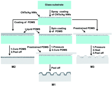 | ||
| Scheme 1 A schematic showing the fabrication process of the CNTs–PDMS or Ag NWs–PDMS stretchable conductors. | ||
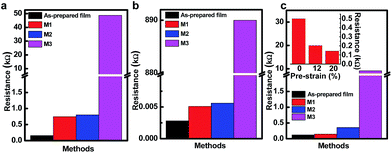
To investigate the influence of fabrication method on the film transfer efficiency, three types of stretchable conductors were prepared as described in Scheme 1. The resistance change of fabricated conductors before and after the transfer are shown in Fig. 1a for CNTs–PDMS and Fig. 1b for Ag NWs–PDMS, here 0% prestrain is applied in M2. We have found that both M1 and M2 samples have similar resistance, which show much lower resistance in comparison with M3 sample, indicating of higher transfer efficiency of percolation networks in M1 and M2. This efficient transfer probably attributed to the stronger adhesion between one dimensional conductors and PDMS matrix during the curing process, the adhesion in M3 is weak during the hot pressing process. More carefully, the resistance of M1 sample is slightly lower than that of M2 sample, suggesting that M1 method has the highest transfer efficiency due to the synergism of direct curing and hot pressing process. Fig. 1c shows the effect of prestrain on the resistance of transferred films, here 20% prestrain is applied to fabricate M1 and M3 samples. In the M1 and M2 samples, the resistance decreases when prestrain is implemented. Furthermore, three M1 samples with 0, 12% and 20% prestrain have been prepared, the resistance also decreases with the prestrain increase (inset of Fig. 1c). This is because prestrained CNTs or Ag NWs can form a more effective electron percolation network after the release.32 Thus, our strategy cannot only transfer film efficiently but also achieve high conductivity.
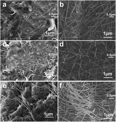
The morphology of the transferred films were studied by scanning electron microscopy (SEM). The transferred CNTs–PDMS and Ag NWs–PDMS films without prestrain were prepared using M1, M2 and M3 methods. Fig. 2a and c show the top-view SEM images of CNTs after being transferred and embedded to PDMS matrix, only scarce CNTs on the very top of PDMS surface are observed, the majority of CNTs are buried below the surface. A similar phenomenon is also observed for Ag NWs–PDMS films, as shown in Fig. 2b and d. When liquid PDMS is coated onto the percolation networks, the liquid can penetrate into the networks due to its low viscosity. After the curing of PDMS, the CNTs or Ag NWs become highly cross-linked with the matrix, thus leading to the high efficient transfer and more continuous surface. Compared to M1 and M2 samples, the morphology of M3 samples is different, CNTs and Ag NWs in M3 sample delaminate from the PDMS substrate and show the buckling of one dimensional conductive materials, as shown in Fig. 2e and f, which is consistent with the previous reported results.29 To evaluate the surface roughness, the root mean square roughness of CNT–PDMS conductors is 69.7 nm for M1, 109.8 nm for M2 and 122.6 nm for M3. The root mean square roughness of Ag NW–PDMS conductors is 20.7 nm for M1, 37.0 nm for M2 and 105.9 nm for M3. Therefore, embedding strategy in M1 and M2 method cannot only obtain smooth surface but also enhance the adhesion of conductors and matrix.
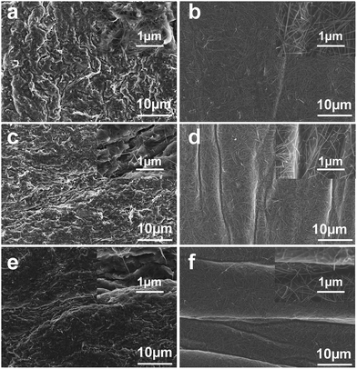
To further investigate the prestrain effect on the morphology of transferred films fabricated by the M1 method. Three M1 samples have been prepared with the prestrain of 0%, 8% and 20%, respectively. Fig. 3 shows the evolution of morphology as a function of the prestrain. It can be seen that the morphology of surface is smooth when a prestrain of 0% is applied (Fig. 3a and b). When a prestrain of 8% is released, strain-induced surface wrinkling can be monitored in the stretching direction (Fig. 3c and d). More obvious wrinkling appear with further increase of the prestrain to 20% (Fig. 3e and f). Meanwhile, no delamination or debonding or cracks are observed in the surface of high stretchable films, which is very similar with the buckled morphology in the literature.30 Note that the morphology of stretchable Ag NWs–PDMS conductors show smoother surface than that in the stretchable CNTs–PDMS conductors under the same prestrain condition, thus Ag NWs as emerging conductors are more promising than others. Based on our discussion above, it is also expected that the wrinkling structure can enhance the stretchability and durability of the transferred films.
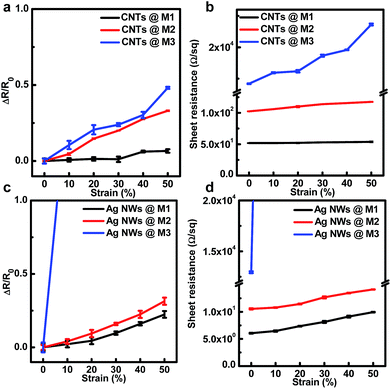
To evaluate the performance of stretchable conductors, both CNTs–PDMS and Ag NWs–PDMS conductors were fabricated through M1 method, with a prestrain of 20%, the thickness of each stretchable conductor is 6 μm for CNT–PDMS conductor and 2.5 μm for Ag NW–PDMS conductor. The electrical resistance and sheet resistance were measured over three locations by using four-point probe method during the tensile test. Fig. 4a and b show the average resistance and sheet resistance of CNTs–PDMS conductors as a function of applied strain, respectively. Compared to M2 and M3 samples, M1 sample exhibit more stable electrical properties, the resistance and sheet resistance remain constant up to 20% strain, which is approximately equal to the prestrain value in the film forming process, indicating the electrical stability dependence of fabrication process. Moreover, beyond 20% strain, both of them increase slowly with the strain increased to 50%, with a resistivity variation of 6.6% under 50% strain and change slightly in sheet resistance, which exhibit higher stretchability compared with the previous reports.33–35 The higher stability probably is attributed to the synergy effects of wrinkling surface structure by the prestrain and enhanced adhesion by the embedding. As shown in Fig. 4c and d, Ag NWs–PDMS system also shows similar trends to that of CNTs–PDMS system. Therefore, our strategy shows promising for fabricating high stretchable conductors based on one dimensional conductive materials.
Durability testing was also carried out to study the durability properties of the M1 samples through multiple strain cycles. Fig. 5 shows the resistance change under 1000 deformation cycles, the resistance was recorded by multimeter at discrete intervals of 50 cycles. Obviously, M1 samples show excellent robustness under repeated mechanical loading in comparison with M2 and M3 samples, no significant change of resistance was observed even after the conductor was stretched for 400 cycles under the strain range of 0–15%, while only a slight increase in resistance (8.2%) was found after 1000 cycles for CNTs–PDMS conductor, as shown in Fig. 5a. The fabricated conductor possess superior cyclic reliability compared with some previous reported conductors.34–36 The cyclic number of our conductor is about 5 times higher than that of the similar CNT–PDMS conductor at a same strain,34 but significantly higher than the cycle number (50) even though they have a large strain.35 Note that similar resistance change behaviour was observed when Ag NWs–PDMS conductor was subjected to stretching along the prestrain axis, and slight resistance change of 7% was observed even after 1000 cycles for Ag NWs–PDMS conductor, as shown in Fig. 5b. The superior electrical stability of M1 samples during durability testing along with the high stretchability indicates that they can function as high performance stretchable conductors.
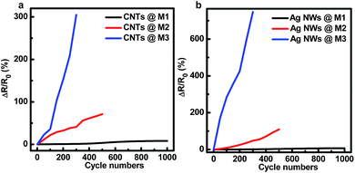 | ||
| Fig. 5 Comparison of resistance change as a function of cycle number for CNTs–PDMS conductors (a) and Ag NWs–PDMS conductors (b). | ||
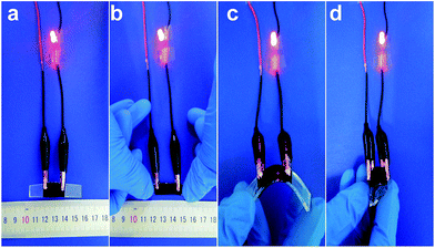
Due to high performance in terms of stretchability, durability, and electrical conductivity, CNTs–PDMS or Ag NWs–PDMS conductors can be directly integrated to high performance stretchable electronics. As a proof-of-concept, we demonstrate a highly stretchable LED circuits with the as-made CNT elastomeric conductor as electrical wires. As shown in Fig. 6a, LED is luminous without an applied strain, and the LED is operational at over 50% strain without any obvious degradation when the conductor is stretched by increasing the tensile strain (Fig. 6b). Besides the simple uniaxial stretching, we also demonstrate that the as-made conductors can be bent in varying bend angles while maintaining stable electrical conductance, as shown in Fig. 6c and d. The above demonstrates that the our strategy is a promising and universal approach in fabrication of high performance stretchable conductors in a simple, solution process, scalable, and potential low cost.
In summary, we have successfully developed a general strategy for the fabrication of high performance stretchable conductors made from one dimensional conductive materials. This strategy, based on the combination of prestrain and embedding, offers competitive advantages over conventional methods for the preparation of stretchable conductors. One thing is that it is a universal method that can be used to prepare different kinds of high performance stretchable conductors with various embedded nanomaterials, such as nanotubes and nanowires. The other is the resulting conductors show high stretchability (no significant degradation in a large tensile strain of 50%), smooth surface, and superior electrical stability (excellent durability over 1000 cycles) in comparison with the conductors by conventional methods. We believe that our novel strategy could be broadly applicable for the facile fabrication of high performance stretchable conductor in future stretchable and wearable electronics.
Acknowledgements
This work was supported by the National Key Basic Research Program of China (973 Program, 2015CB932200), the National Natural Science Funds for Excellent Young Scholars (61622402), the National Natural Science Foundation of China (61376088, 51302134, 51528201), the Jiangsu Specially-Appointed Professor programme, and the Six Talent Plan (2015XCL015).Notes and references
- T. Sekitani, H. Nakajima, H. Maeda, T. Fukushima, T. Aida, K. Hata and T. Someya, Nat. Mater., 2009, 8, 494 CrossRef CAS PubMed.
- A. E. Aliev, J. Oh, M. E. Kozlov, A. A. Kuznetsov, S. Fang, A. F. Fonseca, R. Ovalle, M. D. Lima, M. H. Haque, Y. N. Gartstein, M. Zhang, A. A. Zakhidov and R. H. Baughman, Science, 2009, 323, 1575 CrossRef CAS PubMed.
- D. H. Kim, N. S. Lu, R. Ma, Y. S. Kim, R. H. Kim, S. D. Wang, J. Wu, S. M. Won, H. Tao, A. Islam, K. J. Yu, T. I. Kim, R. Chowdhury, M. Ying, L. Z. Xu, M. Li, H. J. Chung, H. Keum, M. McCormick, P. Liu, Y. W. Zhang, F. G. Omenetto, Y. G. Huang, T. Coleman and J. A. Rogers, Science, 2011, 333, 838 CrossRef CAS PubMed.
- D. J. Lipomi, M. Vosgueritchian, B. C. Tee, S. L. Hellstrom, J. A. Lee, C. H. Fox and Z. Bao, Nat. Nanotechnol., 2011, 6, 788 CrossRef CAS PubMed.
- T. Yamada, Y. Hayamizu, Y. Yamamoto, Y. Yomogida, A. Izadi-Najafabadi, D. N. Futaba and K. Hata, Nat. Nanotechnol., 2011, 6, 296 CrossRef CAS PubMed.
- S. Xu, Y. Zhang, J. Cho, J. Lee, X. Huang, L. Jia, J. A. Fan, Y. Su, J. Su, H. Zhang, H. Cheng, B. Lu, C. Yu, C. Chuang, T.-i. Kim, T. Song, K. Shigeta, S. Kang, C. Dagdeviren, I. Petrov, P. V. Braun, Y. Huang, U. Paik and J. A. Rogers, Nat. Commun., 2013, 4, 1543 CrossRef PubMed.
- C. Wang, W. Zheng, Z. Yue, C. O. Too and G. G. Wallace, Adv. Mater., 2011, 23, 3580 CrossRef CAS PubMed.
- J. A. Rogers and Y. Huang, Proc. Natl. Acad. Sci. U. S. A., 2009, 106, 10875 CrossRef CAS PubMed.
- J. A. Rogers, T. Someya and Y. Huang, Science, 2010, 327, 1603 CrossRef CAS PubMed.
- Y. Liu, Y. Y. Chen, R. Shi, L. J. Cao, Z. Wang, T. Sun, J. J. Lin, J. Q. Liu and W. Huang, RSC Adv., 2017, 7, 4891 RSC.
- K. Y. Chun, Y. Oh, J. Rho, J. H. Ahn, Y. J. Kim, H. R. Choi and S. Baik, Nat. Nanotechnol., 2010, 5, 853 CrossRef CAS PubMed.
- J. Q. Liu, Z. Y. Yin, X. H. Cao, F. Zhao, L. H. Wang, W. Huang and H. Zhang, Adv. Mater., 2013, 25, 233 CrossRef PubMed.
- D. Y. Choi, H. W. Kang, H. J. Sung and S. S. Kim, Nanoscale, 2013, 5, 977 RSC.
- J. Zou, H. L. Yip, S. K. Hau and A. K. Y. Jen, Appl. Phys. Lett., 2010, 96, 203301 CrossRef.
- C. Feng, K. Liu, J. S. Wu, L. Liu, J. S. Cheng, Y. Zhang, Y. Sun, Q. Li, S. Fan and K. Jiang, Adv. Funct. Mater., 2010, 20, 885 CrossRef CAS.
- S. H. Kim, W. Song, M. W. Jung, M. K. W. Kim, S. J. Chang, S. S. Lee, J. Lim, J. Hwang, S. Myung and K. S. An, Adv. Mater., 2014, 26, 4247 CrossRef CAS PubMed.
- Q. Liu, T. Fujigaya, H. M. Cheng and N. Nakashima, J. Am. Chem. Soc., 2010, 132, 16581 CrossRef CAS PubMed.
- S. Park, M. Vosguerichian and Z. Bao, Nanoscale, 2013, 5, 1727 RSC.
- D. Zhang, K. Ryu, X. Liu, E. Polikarpov, J. Ly, M. T. Tompson and C. Zhou, Nano Lett., 2006, 6, 1880 CrossRef CAS PubMed.
- S. Nam, M. Song, D. H. Kim, B. Cho, H. M. Lee, J. D. Kwon, S. G. Park, K. S. Nam, Y. Jeong, S. H. Kwon, Y. C. Park, S. H. Jin, J. W. Kang, S. Jo and C. S. Kim, Sci. Rep., 2014, 4, 4788 Search PubMed.
- T. Akter and W. S. Kim, ACS Appl. Mater. Interfaces, 2012, 4, 1855 CAS.
- T. Tokuno, M. Nogi, M. Karakawa, J. Jiu, T. T. Nge, Y. Aso and K. Suganuma, Nano Res., 2011, 4, 1215 CrossRef CAS.
- D. J. Finn, M. Lotya and J. N. Coleman, ACS Appl. Mater. Interfaces, 2015, 7, 9254 CAS.
- W. Xu, Q. Xu, Q. Huang, R. Tan, W. Shen and W. Song, J. Mater. Sci. Technol., 2016, 32, 158 Search PubMed.
- Q. Huang, W. Shen, X. Fang, G. Chen, J. Guo, W. Xu, R. Tan and W. Song, RSC Adv., 2015, 5, 45836 RSC.
- S. Gong and W. Cheng, Adv. Electron. Mater., 2017, 3, 1600314 CrossRef.
- J. Liang, K. Tong and Q. Pei, Adv. Mater., 2016, 28, 5986 CrossRef CAS PubMed.
- P. Lee, J. Lee, H. Lee, J. Yeo, S. Hong, K. H. Nam, D. Lee, S. S. Lee and S. H. Ko, Adv. Mater., 2012, 24, 3326 CrossRef CAS PubMed.
- F. Xu, X. Wang, Y. T. Zhu and Y. Zhu, Adv. Funct. Mater., 2012, 22, 1279 CrossRef CAS.
- F. Xu and Y. Zhu, Adv. Mater., 2012, 24, 5117 CrossRef CAS PubMed.
- W. Gaynor, G. F. Burkhard, M. D. McGehee and P. Peumans, Adv. Mater., 2011, 23, 2905 CrossRef CAS PubMed.
- J. E. Mates, I. S. Bayer, J. M. Palumbo, P. J. Carroll and C. M. Megaridis, Nat. Commun., 2015, 6, 8874 CrossRef CAS PubMed.
- S. Shang, W. Zeng and X. M. Tao, J. Mater. Chem., 2011, 21, 7274 RSC.
- K. Liu, Y. Sun, P. Liu, X. Lin, S. Fan and K. Jiang, Adv. Funct. Mater., 2011, 21, 2721 CrossRef CAS.
- K. H. Kim, M. Vural and M. F. Islam, Adv. Mater., 2011, 23, 2865 CrossRef CAS PubMed.
- W. Hu, X. Niu, L. Li, S. Yun, Z. Yu and Q. Pei, Nanotechnology, 2012, 23, 344002 CrossRef PubMed.
| This journal is © The Royal Society of Chemistry 2017 |

