 Open Access Article
Creative Commons Attribution 3.0 Unported Licence
Recent developments of carbon based nanomaterials and membranes for oily wastewater treatment
Bader Shafaqa Al-anzi* and
Ong Chi Siang
Department of Environment Technology and Management, College of Life Sciences, Kuwait University, Kuwait. E-mail: alanzi@mit.edu
First published on 12th April 2017
Abstract
Membrane technology has been acknowledged as an advanced separation process of surfactant–stabilized emulsions with allowable discharge quality and a relatively simple process. Despite these unique advantages, the real application of using membranes in industrial fields for treating oily wastewater remains limited. The major problem is severe membrane fouling caused by surfactant adsorption and/or pore plugging by oil droplets as well as degradation over long term application due to its polymeric based structure. In this regard, carbon-based membrane technology has been considered as an attractive technique to fill the gap between membrane technology and existing oily wastewater treatment. This review places a main focus on the recent advances of nanomaterials and carbon-based nanocomposite membrane development for effectively treating emulsified oil/water mixtures. There are four sections in this review. First, a general and brief introduction of the oily wastewater treatment undertaken and the needs of an efficient and broadly applicable approach for the effective separation of various emulsified oily wastewater are given. Secondly, a general overview on research breakthroughs by using various nanomaterials to enhance oily wastewater treatment is provided. This is followed by a review on the current developments of carbon based nanomaterials, nanofibers and membranes based on their fabrication, characterization and separation performance. Some challenges facing the development of carbon based membranes for treating industrial oily wastewater are highlighted at the end of the review.
1. Introduction
Oil contaminated wastewater has been recognized as one of the most concerning pollution sources worldwide. This kind of wastewater comes from a variety of sources such as crude oil production, oil refineries, the petrochemical industry, metal processing, compressor condensates, car washing, lubricants and cooling agents.1 The oil spill incident at Deepwater Horizon that happened in 2010 revealed the difficulties of effective oil–water separation using existing technologies. Oily wastewater is considered as hazardous industrial wastewater because it contains toxic substances such as phenols, petroleum hydrocarbons, and polyaromatic hydrocarbons that are inhibitory to plant and animal growth and possess mutagenic and carcinogenic risks to human being.A variety of treatment methods geared towards the removal of oil impurities can be used to minimize or avoid the adverse effects of oily wastewater. To date, various conventional technologies such as biological media, adsorption, coagulation–flocculation, gravity separation, etc, could be used to separate oil water mixtures. However, the increasing global oil demand has made these treatment processes very challenging. It is mainly because these methods are only useful for free oil solution with oil droplets size >150 μm or unstable oil–water emulsion with droplet size falls in the range of 20–150 μm.2
In order to separate much smaller oil droplets effectively from stable oil–water emulsion numerous studies have been performed to design advanced functional nanomaterials and membranes for oil/water separation.2–12 However, the complicated issues regarding the valuable oil recovery and recycled use of nanomaterials have to be considered in the point of economic view.13,14 Membrane technology on the other hand has been acknowledged as an advanced separation process of surfactant–stabilized emulsions, with allowable discharge quality and a relatively simple process from an operational viewpoint.2,15 Despite these unique advantages, the real application of using membranes in various industrial fields for treating oily wastewater remains limited. The major problem is severe membrane fouling caused by the surfactant adsorption and/or pore plugging by oil droplets, which leads to rapid membrane water flux decline and requires higher frequency of cleaning process.2,15 Moreover, as most of the commercial membranes are made of polymeric materials, they are likely to suffer from structural degradation in the long term application. Therefore, the incorporation of advanced inorganic nanomaterials into the polymer-based membrane matrix is performed with the aim of enhancing membrane surface anti-fouling properties.16 Carbon-based polymer nanocomposite membranes have recently drawn tremendous attentions among membrane scientists due to their excellent chemical and mechanical stability and antifouling properties against oil deposition/adsorption.7,10,17,18
This review places a main focus on the recent advances of advanced nanomaterials and nanocomposite membranes incorporated with carbon based nanomaterials and nanofibers for effectively treating emulsified oil/water mixtures. There are two main carbon nanomaterials would be focused on, i.e. carbon nanotubes and graphene, which have been considered as a revolutionary technological breakthrough towards the water and wastewater treatment. After that, the recent advances of carbon membranes in terms of fabrication, characterization, flux performance and oil separation efficiency would be critically reviewed. Some future outlooks and challenges on the development of carbon based membranes would be given in the end of chapter.
2. Advanced materials for oily wastewater treatment
Over the past decade, nanomaterials and nanotechnologies have rapidly transformed from an academic pursuit to commercial reality. To efficiently separate the increasing amount of oily wastewater, four kinds of surface wetting properties must be considered for selecting the proper nanomaterials,11 i.e., hydrophobic and oleophilic, hydrophilic and oleophobic, superhydrophilic and superoleophobic, and responsive/switchable wetting properties. A brief summary of various nanomaterials used on the separation of emulsified oil/water mixture is provided in Table 1. As demonstrated from table, superwetting nanomaterials which are fabricated based on different surface chemical composition and nanostructured surface roughness have been extensively studied in order to develop a new strategy for effective, energy-efficient and simple oil/water separation with a series of advanced functions such as high permeability, catalytic reactivity, self-cleaning ability and fouling resistance. It is possible to construct superwetting nanomaterials by choosing the appropriate materials and generating enough surface roughness.| Materials | Coating method and support | Types of mixture | Contact angle | Separation efficiency | Ref. | Remarks |
|---|---|---|---|---|---|---|
| Hydrophobic and oleophilic properties | ||||||
| Attapulgite | Spray-coating (stainless steel mesh) | Hexadecane/water mixture, lubrication oil/water mixture, and paroline/water mixture | Water contact angle (WCA): 160 ± 1°; oil contact angle (OCA): 0° | 98% | Yang et al.25 | |
| Epoxy/attapulgite | Spray-coating (stainless steel mesh) | Kerosene and water mixture | WCA: 155°; OCA: 0° | 97% | Li et al.26 | |
| Zinc oxide (ZnO) | Dip-coating (stainless steel mesh) | Toluene and water mixture | WCA: 160°; OCA: 0° | N/A | Wang et al.27 | |
| Polyaniline (PANI) and polypyrrole (PPy) | Dip-coating (stainless steel mesh) | Hexane, petroleum ether, gasoline, diesel, and soya bean oil | WCA: 154°; OCA: 0° | 96–99.8% | Xiao et al.28 | |
![[thin space (1/6-em)]](https://www.rsc.org/images/entities/char_2009.gif) |
||||||
| Hydrophilic and oleophobic properties | ||||||
| Fluorodecyl polyhedral oligomeric silsesquioxane (POSS) and cross-linked poly(ethylene glycol) diacrylate (x-PEGDA) | Dip-coating (stainless steel mesh) | Oil and water mixture | WCA: 0°; OCA: 150° | 99.90% | Kota et al.8 | |
| Montmorillonite (MTM)-poly(diallyldimethylammonium chloride) (PDDA) | Layer-by-layer (LBL) method | 1,2-Dichloroethane, trichloromethane, n-hexane, petroleum ether, crude oil | WCA: 0°; OCA: 162.1–168.7° | N/A | Xu et al.23 | |
![[thin space (1/6-em)]](https://www.rsc.org/images/entities/char_2009.gif) |
||||||
| Superhydrophilic and superoleophobic properties | ||||||
| Paraffin wax (PFW) and poly(dimethylsiloxane)-b-poly(ethylene oxide) (PDMS-b-PEO) diblock copolymer | Dip-coating (cellulose membrane) | Oil, water | WCA: 125.8 ± 2.3°; OCA: 0° | 99% | Paul et al.20 | |
| Poly(diallyldimethylammonium chloride) (PDDA), oleophobic sodium perfluorooctanoate (PFO) and SiO2 nanoparticles | Spray-coating (stainless steel mesh) | Rapeseed oil, diesel and dodecane | WCA: 0°; OCA: >150° | N/A | Yang et al.29 | |
| Cu(OH)2 nanowires | Dip-coating (Cu mesh) | Oil, water | WCA: 0; OCA: 155 | N/A | Zhang et al.21 | |
| Poly(2-methacryloyloxyethyl phosphorylcholine) (polyMPC)-polydopamine (PDA) | Dip-coating (silicone (Si) wafer) | Chloroform, water | WCA: <10°; OCA: >150° | N/A | Chang et al.30 | |
| NiOOH (a high oxidation product from Ni(OH)2 and persulfate) | Chemical bath deposition (CBD) (metal mesh consisting of stainless steel and copper thread) | Dichloroethane, hexane, petroleum ether and vacuum pump oil | WCA: 0; OCA: 152° | 98–99% | Li et al.31 | |
![[thin space (1/6-em)]](https://www.rsc.org/images/entities/char_2009.gif) |
||||||
| Responsive/switchable properties | ||||||
| Poly(dimethylamino) ethyl methacrylate (PDMAEMA) hydrogel | Dip-coating (stainless steel mesh) | 1,2-Dichloroethane, gasoline/0.1 M HCl solution, gasoline/water | WCA: 151 ± 0.8°; OCA: 0° | 99.97% | Cao et al.6 | pH and thermo responsive |
| Cu–Au-HS(CH2)9CH3 and HS(CH2)10COOH | Dip-coating (Cu mesh) | n-pentane, n-hexane, n-heptane, methylbenzene, dichloromethane, chloroform, 1,2-dichloroethane and 1,1,2,2-tetrachloroethane | WCA: 140–160°; OCA: 0° | 99% | Wang et al.32 | pH responsive |
| Poly(dodeyl methacrylate-co-3-trimethoxysilylpropyl methacrylate-co-2-dimethylaminoethyl methacrylate) (PDMA-co-PTMSPMA-co-PDMAEMA) | Dip coating (cotton fabric and filter paper) | Gasoline, dichloromethane, hexane, toluene and water | WCA: 120–150°; OCA: 0° | 99% | Dang et al.24 | pH responsive (as shown in Fig. (2)) |
Many research works have been carried out by designing and fabricating superwetting nanomaterials including superwetting absorbing nanomaterials and superwetting separation membranes to achieve oil/water separation.13 As superwetting nanomaterials exhibit excellent hydrophilicity and oleophobicity or oleophilicity and hydrophobicity properties in water-rich or oil-rich conditions, they can be used for effective oily wastewater treatment by selective absorption or permeation. For instances, the superhydrophilic-underwater superoleophobic nanomaterials have shown a very high water affinity but very low underwater oil adhesion force, resulting in higher water permeation and excellent oil repellent under water. On the contrary, the superoleophilic–superhydrophobic nanomaterials exhibit a very high oil affinity and very high water-repellent ability, which enables oil go through or absorbs oil but rejects water, consequently achieving the effective separation of oil and water.13
Although various hydrophobic and oleophilic materials have been developed and proven to be very promising in the selective oil/water separation, their high affinity towards oils makes them easily fouled. Moreover, a water barrier will form between the filtration material and the oil layer, which blocks the filtration process.19 In contrast, hydrophilic and oleophobic materials, which can selectively allow water passing through, can avoid these problems. For instances, Kota and his co-workers8 developed dip-coated stainless steel mesh 100 and polymer fabric by blending 20 wt% fluorodecyl polyhedral oligomeric silsesquioxane (POSS) and cross-linked poly(ethylene glycol) diacrylate (x-PEGDA). It was reported that the novel membrane was posed with hygro-responsive surfaces, which are both superhydrophilic (water contact angle (WCA) ≈ 0°) and superoleophobic (oil contact angle >150°) either in air or under water. As shown in Fig. 1, the water-rich permeate passed through the membrane while the hexadecane-rich retentate was retained above the membrane within minutes (see Fig. 1(b)). Membrane oleophobicity under water was critical for the separation of hexadecane-in-water emulsions (Fig. 1(a), inset). The result was further proven using thermogravimetric analyses (TGA) as illustrated in Fig. 1(c). It could be seen that the permeate contained ∼0.1 wt% hexadecane, whereas the retentate contained ∼0.1 wt% water. Fig. 1(d) and (e) show the solely gravity-driven capillary force-based separation (CFS) of a water-in-oil emulsion (30 vol% water) stabilized using another type of nanomaterial known as Polysorbate80 (PS80). The apparatus was the same as that used for the separation of oil-in-water emulsions. The emulsion was added to the upper tube (see Fig. 1(d)). Once water droplets within the emulsion contacted the membrane, the surface started to reconfigure. Before the breakthrough of the water-rich permeate, hexadecane was retained above the membrane because of membrane oleophobicity in air. After surface reconfiguration, the water-rich permeate passed through the membrane while the hexadecane-rich retentate was retained above the membrane (see Fig. 1(e)). During the permeation of the water-rich permeate, the hexadecane-rich retentate was retained above the membrane because of membrane oleophobicity under water. Overall, membrane oleophobicity, both in air and under water, is critical for separating water-in-hexadecane emulsions.
 | ||
Fig. 1 (a) Separation apparatus with a 50![[thin space (1/6-em)]](https://www.rsc.org/images/entities/char_2009.gif) : :![[thin space (1/6-em)]](https://www.rsc.org/images/entities/char_2009.gif) 50 v 50 v![[thin space (1/6-em)]](https://www.rsc.org/images/entities/char_2009.gif) : :![[thin space (1/6-em)]](https://www.rsc.org/images/entities/char_2009.gif) v hexadecane-in-water emulsion above the membrane. Inset, hexadecane droplet on a surface spin-coated with a 20 wt% fluorodecyl POSS + x-PEGDA blend, submerged in water containing dissolved SDS (1 mg mL−1). (b) Water-rich permeate passes through the membrane whereas hexadecane-rich retentate is retained. (c) TGA data for the permeates and the retentates. HD, hexadecane. (d) Apparatus with a 30 v hexadecane-in-water emulsion above the membrane. Inset, hexadecane droplet on a surface spin-coated with a 20 wt% fluorodecyl POSS + x-PEGDA blend, submerged in water containing dissolved SDS (1 mg mL−1). (b) Water-rich permeate passes through the membrane whereas hexadecane-rich retentate is retained. (c) TGA data for the permeates and the retentates. HD, hexadecane. (d) Apparatus with a 30![[thin space (1/6-em)]](https://www.rsc.org/images/entities/char_2009.gif) : :![[thin space (1/6-em)]](https://www.rsc.org/images/entities/char_2009.gif) 70 v 70 v![[thin space (1/6-em)]](https://www.rsc.org/images/entities/char_2009.gif) : :![[thin space (1/6-em)]](https://www.rsc.org/images/entities/char_2009.gif) v water-in-hexadecane emulsion above the membrane. Inset, hexadecane droplet on a surface spin coated with a 20 wt% fluorodecyl POSS + x-PEGDA blend, submerged in water containing dissolved PS80 (1 mg mL−1). (e) Water-rich permeate passes through the membrane whereas hexadecane-rich retentate is retained. Water is dyed blue and hexadecane is dyed red. Scale bars = 2 cm.8 v water-in-hexadecane emulsion above the membrane. Inset, hexadecane droplet on a surface spin coated with a 20 wt% fluorodecyl POSS + x-PEGDA blend, submerged in water containing dissolved PS80 (1 mg mL−1). (e) Water-rich permeate passes through the membrane whereas hexadecane-rich retentate is retained. Water is dyed blue and hexadecane is dyed red. Scale bars = 2 cm.8 | ||
Furthermore, as inspired by the oleophobicity of fish scales, superhydrophilic/underwater superoleophobic materials have been proposed in water-rich mixtures that allow water permeation but prevent oil penetration in the underwater application.20–23 In general, superhydrophilic-underwater superoleophobic materials, especially separation membranes which possess opposite superwetting behaviours for water and oil in a water-rich environment, are widely explored in the field of oil/water separation. A surface that is superhydrophilic in air will exhibit superoleophobicity underwater. This is because the superhydrophilic surface will trap water molecules onto its hierarchical surface structure to reach a low-energy state.11
Many recent studies were focused on responsive/switchable wettable materials as their wettability can be switched upon applying an external stimulus such as light, pH, and temperature or treatment with specific chemicals. Materials with responsive wettability can switch from wetting (superwetting) to antiwetting (super-antiwetting), or vice versa. Therefore, the responsive wettable material offers a significant advantage for controllable oil/water separation in the harsh environmental condition. Dang and co-workers24 for instance designed a novel pH responsive nonfluorine-containing copolymer. The copolymer together with silica can be dip-coated on different materials including cotton fabric, filter paper, and polyurethane foam. The coated materials exhibit switchable superhydrophilicity and superhydrophobicity (as shown in Fig. 2) and can be applied in continuous separation of oil/water/oil three phase mixtures, different surfactant stabilized emulsion (oil-in-water, water-in-oil, and oil-in-acidic water) as well as oil uptake and release via in situ and ex situ pH change.24
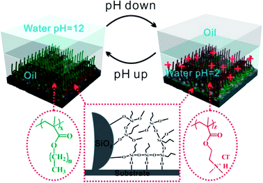 | ||
| Fig. 2 Mechanism of pH responsive coatings. At high pH values, poly(alkyl methacrylate) are stretched in oil (left panel). At low pH, poly(2-dimethylaminoethyl methacrylate) (PDMAEMA) PDMAEMA is protonated and it exhibits an extended conformation (right panel). Poly(3-trimethoxysilylpropyl methacrylate) (PTMSPMA) reacts with SiO2 nanoparticles and underlying substrate to improve the adhesion strength (middle panel).24 | ||
3. Carbon based nanomaterials for oily wastewater treatment
Although the advanced materials mentioned in previous section (Table 1) exhibit promising surface properties, they are mostly not effective for separating oil/water emulsions, especially for surfactant–stabilized emulsions with droplet sizes below 20 mm,33 and a secondary treatment is required to separate the materials from the process, thus restricting their real potential applications in oil/water separation.2,34 Thus, it is of great significance to develop materials that are more sustainable and scalable to realize the separation of oil/water emulsions. Herein, carbon-based nanomaterials have drawn tremendous attentions among membrane scientists due to their low cost, superior chemical and mechanical stability, and highly integrated operation. Of various carbon based nanomaterials, carbon nanotubes (CNTs) and graphene have caused a lot of interests in oil removal studies due to their exceptional one-dimensional structure, large specific surface area, oleophilic and hydrophobic in nature.7,143.1 Carbon nanotubes
Many researchers have reported the beneficial advantages of adding CNTs to polymeric membranes. These include increased hydrophilicity and oleophobicity,35 improved thermal,36 electrical,37 and mechanical3 properties of the composite membranes. CNTs as nanofiller in polymer matrix have attracted a great deal of attention because of their high specific surface area, easy functionalization, chemical stability and proper compatibility.17 Well-aligned CNT can serve as robust pores in membranes for water purification.38 The hollow CNT structure meanwhile provides frictionless transport of water molecules for enhanced water permeability. By designing appropriate pore diameters, it can constitute energy barriers at the channel entries, rejecting salt ions and permitting water through the hollow nanotubes.39 It is also possible to modify CNT pores to selectively reject ions.5 Thus, CNT membrane can be used as a ‘gate keeper’ for size controlled separation of multiple pollutants. Furthermore, CNTs have antifouling, self-cleaning and reusable functions.Liu et al.10 reported a fast and efficient method to separate emulsified oil from oily wastewater using functionalized multiwalled carbon nanotubes (F-MWCNTs) as a demulsifier. They found that F-MWCNTs could remove 99.8% oil from the emulsified oily wastewater within a few minutes. The lowest oil content in the separated water was about 56 mg L−1 (from an initial oil concentration of 1741.2 ± 34.2 mg L−1), while the water content in the separated oil phase was as low as 0.45%, meeting the standard of oil transportation and oil refinery. They believed that the strong affinity of F-MWCNTs with the oil droplets was attributed to the demulsification of oil droplets via the breakdown of asphaltenes/resins protective film attached on the oil droplets caused by the strong interaction between F-MWCNTs and asphaltenes/resins through π–π and/or n–π interactions.10
Recently, many researchers found that CNTs could be covalently attached onto the surface of polymer to produce hybrid CNTs/polymer membranes for efficient separation of surfactant–stabilized oil/water emulsions.35,40 Gu and his co-workers40 developed a novel Ag/polyacrylic acid (PAA)–CNTs hybrid membranes for treating oil/water/solid three-phase system. From Fig. 3(a)–(c), it could be seen that the as-prepared membranes cannot be wetted by oil (chloroform). The developed Ag/PAA–CNTs membranes presented unique under-water superoleophobic characteristics for various organic solvents, including dichloromethane and carbon tetrachloride. The wetting behavior under toluene (Fig. 3(d)–(f)) further confirmed the superhydrophilicity of the Ag/PAA–CNTs hybrid membrane. These findings demonstrated that the newly developed membrane can effectively separate a wide range of surfactant–stabilized oil-in-water emulsions with a remarkable flux of 3000 L m−2 h−1 bar−1. In addition, the hybrid membranes also exhibited an excellent anti-bacterial effect due to the incorporation of AgNPs on the carbon-based membrane as shown in Fig. 4(a)–(f). From the microscopical images, E. coli bacterial cells were destroyed after incubating with the Ag/PAA–CNTs membrane, indicating the antibacterial ability of the developed membrane.
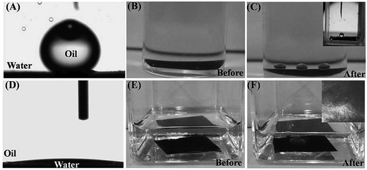 | ||
| Fig. 3 Photographs of (A) an oil droplet (5 mL) on the surface of as prepared Ag/PAA–CNTs membrane under water, (B) a Ag/PAA–CNTs membrane under water, (C) under-water superoleophobicity of the as-prepared Ag/PAA–CNTs membrane in the oil/water/solid three phase system for chloroform, inset, contact angle picture of chloroform; (D) a water droplet (3 mL) on the surface of as-prepared Ag/PAACNTs membrane under toluene, (E) a Ag/PAA–CNTs membrane under toluene, (F) under-oil superhydrophilicity of the as-prepared Ag/PAACNTs membrane in the water/oil/water/solid three-phase system for water. Inset, contact angle picture of water.40 | ||
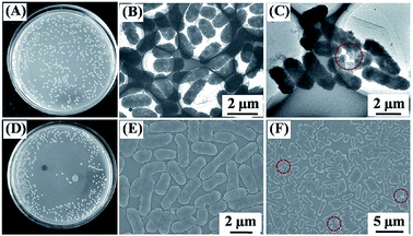 | ||
| Fig. 4 Photographs of colonies formed by E. coli cells (A) in water samples and (D) being incubated with Ag/PAA–CNTs membrane. TEM and SEM images of (B and E) E. coli cells before and (C and F) E. coli cells damaged after filtrating from the as-prepared Ag/PAA–CNTs membrane.40 | ||
Saadati et al.41 on the other hand prepared a new PSf/Pebax composite membrane by coating with different loadings of F-MWCNT at 0.5, 1 and 2 wt%. Pebax is a group of copolymers including hard polyamide (PA) segments and soft polyether (PE) segments. The surface of membranes was nearly smooth and defect free. A dense Pebax layer was formed on the porous PSf layer and there was no evidence of interface voids or sieve in the morphology of these membranes. It was reported that by increasing F-MWCNT loading, the water contact angle decreased and consequently increased membrane hydrophilicity. Tensile strength of membrane was increased by addition of F-MWCNT. Furthermore, adding F-MWCNT to polymer matrix enhanced thermal stability of membrane. Meanwhile, permeate flux was increased with increasing F-MWCNT content up to 0.5 wt%, but permeate flux decreases with further increasing F-MWCNT from 0.5 wt% to 2 wt%. Rejection of oil/water emulsion was higher at lower pressure and decreases with increasing operating pressure, meanwhile oil rejection increased with increasing F-MWCNT loading. Another similar work conducted by Moslehyani et al.42 using PVDF-MWCNT nanocomposite membrane in the presence of TiO2 suspension revealed that optimum water flux, photodegradation and separation efficiency of 710 L m−2 h−1, 90% and 99%, respectively, could be achieved by 200 ppm TiO2 suspension and 1 wt% of MWCNTs embedded with PVDF membrane at 100 ppm oil.
Besides that, Maphutha and his co-workers43 have studied CNT integrated polymer composite membrane with a polyvinyl alcohol (PVA) coating layer to separate oil from water for treatment of oil-containing waste water. The CNTs were synthesised using chemical vapour deposition, and a phase inversion method was employed to prepare CNTs-incorporated flat sheet membrane. Compared to pristine membrane, an increase of 119% in the tensile strength, 77% in the Young's modulus and 258% in the toughness could be achieved when an optimum CNTs concentration of 7.5% was presented in the PSf membrane. The permeate through the membrane showed oil concentrations below the acceptable 10 mg L−1 limit with an excellent flux of 350 L m−2 h−1 and oil rejection of over 95%.43
Zhang and co-workers35 further enhanced the properties of a CNTs-based hybrid film with the incorporation of gold nanoparticles attached on polystyrene (PS) film (see Fig. 5). To achieve multifunctional separation membranes with flow-through catalytic performance, catalysis nanoparticles – gold nanoparticles (AuNPs) were attached densely on the PS microspheres and further assembled into a compacted catalytic microspheres membrane supported on a filtration film as shown in the figure. Upon deposition of the polyacrylic acid-modified CNTs membrane, the resultant composite membranes possessed a superhydrophilic/underwater superoleophobic upper surface and catalytic underlayer. Such a hierarchical composite membrane could be used for the separation of insoluble oil emulsion from water owing to its special surface wettability, and further exhibited flow-through catalytic degradation of organic pollutants in permeated water by flowing along the tortuous channels between hybrid PS@AuNPs microspheres.
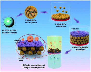 | ||
| Fig. 5 Schematic illustration of the fabrication of underwater superoleophobic CNTs/PS@AuNPs composite membrane with a flow through catalytic decomposition function.35 | ||
The as-prepared membrane have possessed multi-functions of flow-through catalytic degradation of soluble organic molecules and oil/water emulsion separation. The results showed that the catalytic composite membranes could achieve a decomposition of 92.6% nitrophenol in oily wastewater. As demonstrated in Fig. 6, the multifunctional composite membrane showed a maximum flux as high as 3500 L m−2 h−1 bar−1 and exhibited good catalytic recyclability and durability.35
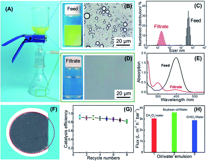 | ||
| Fig. 6 A photograph of separation of soybean oil/water emulsions and flow-through catalytic degradation of 4-NP in water on the CNTs/PS@AuNPs membrane (A). A photograph and microscopic image of the feed emulsion (B) and filtrate (D). The oil droplet sizes (C) and UV/vis absorption spectra (E) of the feed emulsion and filtrate. A photograph of the composite membrane after three times of separation (F). The catalytic decomposition efficiency of the membranes versus the recycle numbers (G). The fluxes of various emulsions passing through the composite membranes (H).35 | ||
3.2 Graphene
Since the first report on graphene in 2004 by Geim and Novoselov,44 graphene and its derivatives have been widely studied and applied to prepare high-performance materials or functional materials.45 Inspired by the two-dimensional structure and hydrophobic property, some researchers begun to use graphene or graphene-related materials to fabricate superhydrophobic materials for oil–water separation in recent years.9,46 Graphene is of interest as advanced material for various membrane-based separations, because of its exceptional physical and thermal properties and atomic scale thickness. Its atomic scale pores generated by chemical or thermal treatment can play as robust channel for water transport or ion, gas, and nanoparticle separations. Pristine graphene is not promising for hybrid membranes, because it does not form homogeneous composites with polymer matrix. Furthermore, graphite and graphene are generally hydrophobic in nature which limits their application in water filtration.47Graphene oxide (GO), the oxidation state of graphene nanosheets, could be an attractive candidate as a carbon filler because it contains epoxide, hydroxyl, and carboxylic acid groups at the edges and basal plane of the nanosheets, which can provide good compatibility with polymers. When appropriately embedded into the polymer matrix, GO can significantly improve mechanical properties of the polymer host, even at low filling amounts.48 When oriented horizontally in the polymer matrix, GO nanosheets may act as barrier, because they hinder diffusion pathway of permeating molecules across the membranes. A certain small amount range of GO can produce tortuous pathways that restrict the diffusion of larger molecules while still allowing smaller molecules diffuse with less resistance. Since hydroxyl (OH) groups are bonded to the surface of the GO nanosheets, these nanosheets are capable of forming aqueous solutions and further enhance the hydrophilicity of polymeric membrane.49
Prince and his co-workers50 have shown a simple method to increase the hydrophilicity of the polyethersulfone (PES) hollow fibre UF membrane by using carboxyl, hydroxyl and amine modified graphene attached polyacrylonitrile-co-maleimide (G-PANCMI). The prepared membranes were characterized for its morphology, water and oil contact angle, liquid entry pressure of oil (LEPoil), water permeability and finally subjected to a continuous 8 h filtration test of oil emulsion in water. It was found that the water contact angle (CAwater) of the PES incorporated with G-PANCMI membrane is reduced from 63.7° to 22.6°, which is 64.5% reduction. Meanwhile, the oil contact angle was increased from 43.6° in the control PES membrane to 112.5° in the PES-G-PANCMI membrane. Similarly, the LEPoil increased by 350% from 50 kPa of the control PES membrane to 175 kPa of modified PES membrane. More importantly, the water permeability of PES-G-PANCMI increased by 43% with an excellent oil selectivity (>99%).
Zhang et al.51 on the other hand fabricated a novel hierarchically structured membrane by assemblying GO sheets on the surface of electrospun aminated polyacrylonitrile (APAN) fibers. This membrane which was superhydrophilic and low-oil-adhesion exhibited ultra-high flux (10![[thin space (1/6-em)]](https://www.rsc.org/images/entities/char_2009.gif) 000 L m−2 h−1), preferable rejection (≥98%) and remarkable antifouling performance for the separation of oil–water emulsion as shown in Fig. 7. The ultra-high flux was attributed to the large porosity of GO/APAN membrane, whereas the preferable rejection ratio and remarkable antifouling performance were attributed to the smaller GO sheets modified on the APAN fibers and larger GO sheets connected to two or more APAN fibers. More importantly, GO/APAN membrane also exhibited supernormal stability in treating oil–water emulsion with a broad pH range or high-concentration salt, which indicated that the membrane was promising for practical use in oily wastewater.
000 L m−2 h−1), preferable rejection (≥98%) and remarkable antifouling performance for the separation of oil–water emulsion as shown in Fig. 7. The ultra-high flux was attributed to the large porosity of GO/APAN membrane, whereas the preferable rejection ratio and remarkable antifouling performance were attributed to the smaller GO sheets modified on the APAN fibers and larger GO sheets connected to two or more APAN fibers. More importantly, GO/APAN membrane also exhibited supernormal stability in treating oil–water emulsion with a broad pH range or high-concentration salt, which indicated that the membrane was promising for practical use in oily wastewater.
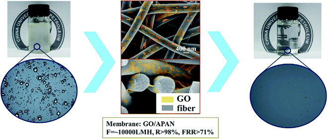 | ||
| Fig. 7 The schematic diagram of the oil trapped inside the GO/APAN membrane.51 | ||
Recently, Hu and his co-workers52 successfully synthesized a novel GO modified commercial 19 channels ceramic membrane via the vacuum method. During the treatment of oil/water emulsion, the water permeation fluxes of unmodified and modified membranes were about 522 and 667 L m−2 h−1 bar−1 after 150 min, respectively. The flux of the modified membrane is 27.8% higher than that of the unmodified membrane as illustrated in Fig. 8(a). Fig. 8(b) showed the permeate of GO modified membrane had lower oil content compared with that of the unmodified membranes throughout the entire process, and the oil rejections for the unmodified and modified membranes were 98.1% and 98.7% after 120 min, respectively. All these indicate that GO modification plays the crucial role and endows the membrane with excellent oil/water separation performance.
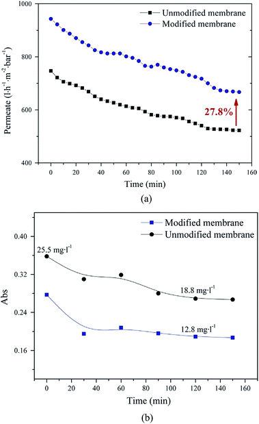 | ||
| Fig. 8 Time-dependent (a) permeate flux (b) oil content of permeate for GO modified and unmodified membranes.52 | ||
Similarly, Huang et al.53 designed and fabricated a GO ultrafiltration (UF) membrane structure with an optimized hierarchical surface roughness using a facile vacuum filtration approach. The effect of coating GO layer thickness on polyamide (PA) support was studied. It was found that the permeate flux of pure PA support was decreased more dramatically than that of GO coating PA support, with an almost 100% flux recovery being achieved even after 3 cycles of cleaning process for all different types of membranes. The water flux was able to be maintained throughout the experiment due to the ultrathin GO coatings that wrapped the polymer skeleton and preserved the pores of the support, thus have positive contribution to the anti-fouling behaviour of the GO coated PA membrane.
Besides that, Ho et al.54 synthesized novel GO/OMWCNTs mixed-matrix PVDF membrane via in situ colloidal precipitation method. The effect of ratio (0![[thin space (1/6-em)]](https://www.rsc.org/images/entities/char_2009.gif) :
:![[thin space (1/6-em)]](https://www.rsc.org/images/entities/char_2009.gif) 10, 1
10, 1![[thin space (1/6-em)]](https://www.rsc.org/images/entities/char_2009.gif) :
:![[thin space (1/6-em)]](https://www.rsc.org/images/entities/char_2009.gif) 9 and 5
9 and 5![[thin space (1/6-em)]](https://www.rsc.org/images/entities/char_2009.gif) :
:![[thin space (1/6-em)]](https://www.rsc.org/images/entities/char_2009.gif) 5) and dosage (0.001, 0.01 and 0.1 g L−1) of GO/OMWCNTs in the coagulation bath are evaluated based on the membrane characteristics and its performance on diluted aerobic palm oil mill effluent (POME) treatment. It was observed that the membrane permeability was increased from 38.98 L m−2 h−1 bar−1 to 43.99 L m−2 h−1 bar−1 with the increment GO/OMWCNTs coagulation bath concentration from 0.001 g L−1 to 0.1 g L−1. Meanwhile, by using 0.1 g L−1 of OMWCNTs in coagulation bath, the rejection of TDS, phosphorus, hardness, chemical oxygen demand (COD), chlorine, turbidity, color, and total suspended solids (TSS) were improved with a percentage of 1.51%, 6.55%, 21.79%, 75.5%, 76%, 81.94%, 86.3%, and 100%, respectively, as compared with the pristine membrane. They further demonstrated that the incorporation of GO/OMWCNTs into membrane matrix could reduce the surface roughness and formed a negative charge repulsive boundary barrier that enhanced antifouling properties, which might have positive impact to the POME treatment.
5) and dosage (0.001, 0.01 and 0.1 g L−1) of GO/OMWCNTs in the coagulation bath are evaluated based on the membrane characteristics and its performance on diluted aerobic palm oil mill effluent (POME) treatment. It was observed that the membrane permeability was increased from 38.98 L m−2 h−1 bar−1 to 43.99 L m−2 h−1 bar−1 with the increment GO/OMWCNTs coagulation bath concentration from 0.001 g L−1 to 0.1 g L−1. Meanwhile, by using 0.1 g L−1 of OMWCNTs in coagulation bath, the rejection of TDS, phosphorus, hardness, chemical oxygen demand (COD), chlorine, turbidity, color, and total suspended solids (TSS) were improved with a percentage of 1.51%, 6.55%, 21.79%, 75.5%, 76%, 81.94%, 86.3%, and 100%, respectively, as compared with the pristine membrane. They further demonstrated that the incorporation of GO/OMWCNTs into membrane matrix could reduce the surface roughness and formed a negative charge repulsive boundary barrier that enhanced antifouling properties, which might have positive impact to the POME treatment.
Overall, most GO incorporated membrane technologies are still in the research & development stage, it is expected that pilot scale level towards the commercial market will grow rapidly.55 Although maturation and commercialization of technologies are difficult to predict, this can be the most promising technology for the oil industrial wastewater treatment. GO-based membrane strategies are expected to have more immediate market potential due to comparatively low cost and relatively simpler system integration. Nevertheless, more information is still needed to establish the understanding of material processing, material structure and properties, membrane applications and their relationships. There is a need for more detailed understanding in terms of material structures with desired properties and further translation of these properties into practical applications through integration of graphene based material and support membranes.56 In summary, more research works are needed to evaluate the cost-effectiveness of large scale membrane fabrication and monitoring of the long-term stability of membranes under practical application conditions.
4. Carbon nanofibers
Recently, the fabrication of nanofibrous materials in terms of sorbents,57 membranes,58 and aerogels59 have shown a rapid expansion of research due to its simple and effective oil/water separation. Fibrous materials including cotton fibers,60 cellulose acetate nanofibers,58 fibrous polymer61 have shown enhanced oil sorption capacities for the oil water separation. Some of these sorbents can be produced by electrospinning, which is a simple top-down method to fabricate fibrous polymer films with chemical inertness, high porosity, uniform pass through size and interconnected open pore structure.4,62 However, almost all of these sorbents are made of either organic polymers or biological fibers, which may be swollen or even dissolved in the oil absorption process when being recycled by rinsing with organic solvents.63 Herein, carbon based fibrous materials can overcome these problems.For instances, Liu et al.64 developed a carbon nanofiber film with sublimation method by using terephthalic acid (PTA) as the sublimating agent to generate macropores inside electrospun carbon nanofibers. During carbonization of electrospun PTA-PAN composite nanofibers, PTA sublimed and macropores were created inside the carbon nanofiber matrix. By inducing macropores inside the carbon nanofiber matrix, macropores within the carbon nanofibers reduced stresses when the fibers were bent, thus enhancing the flexibility of the fiber. The flexible macroporous carbon nanofiber film (MCNFF) exhibited superhydrophobic and superoleophilic properties and a large porosity degree of 89.2% due to the porous electrospun nonwoven structure, and possessed high oil-absorption capability of up to 138.4 g g−1 for silicone oil. They also mentioned that the absorbed oil could be extracted from the membrane through various organic solvents and the MCNFF could be used at least five times without significant loss of its capacity, exhibiting excellent recyclability which is critical to avoid the secondary pollution.
Tai and his co-workers65 on the other hand, have developed a novel free-standing and flexible electrospun carbon-silica composite nanofibrous membrane. It is found that the composite membrane is tougher than the pristine carbon nanofiber (CNF) membrane when the embedded SiO2 concentration is kept at 2.7 wt%, beyond which the membrane toughness is reduced. After coated with silicone oil, the composite membrane becomes ultra-hydrophobic and superoleophilic. The composite membrane exhibited ultra-hydrophobic and superoleophilic properties with water and oil contact angles being 144.2 ± 1.2° and 0°, respectively. They reported that the wettability of the coated composite membrane is resistant to elevated temperature (up to 350 °C) and stable towards a wide range of pH values (2–14). Thus, such wetting behavior allowed the membrane to be applied as a substrate for separation of free water and oil. The quality test of oil–water separation showed that the membrane was highly effective in separating free oil and water. More importantly, the separation process was ultrafast and driven solely by gravity as shown in Fig. 9(a)–(c). From Fig. 9(d), it could be seen that the average permeate flux for petroleum spirit, iso-octane, and hexane was found to be 3032.4 ± 234.6, 1719.1 ± 36.2, and 2648.8 ± 89.7 L m−2 h−1, respectively, with a membrane thickness of 213 nm.
 | ||
| Fig. 9 Ultrafast gravity-driven oil–water separation. (a) Mixture of petroleum spirit and HCl aqueous solution as feed. (b) Whitish AgCl precipitate formed after HCl reacts with AgNO3 solution (violet). (c) Demonstration of gravity-driven oil–water separation. Enlarged pictures show that water is completely retained on the membrane surface and no AgCl precipitate is formed during the separation. (d) Permeate flux for different types of oils. The inset shows the cross-sectional view of the membrane thickness.65 | ||
Overall, when compared to the conventional pressure-driven filtration membranes, the use of electrospun carbon fibrous membrane for oil–water separation takes more advantageous because of its high energy efficiency (separation by gravity), significantly high permeate fluxes and separation performance, and being able to work effectively under harsh conditions such as leakage of high temperature oils because of its strong thermal and chemical resistance.57,58 However, the complicated and time-consuming process of oil recovery from these nanofibers is an obstacle to their practical application. To solve these problems, intensive efforts should be focused on achieving the continuous collection of oil spills in situ from the water surface with high speed and efficiency.
5. Carbon membranes
Although the carbon nanomaterials incorporated with polymeric membranes mentioned in previous section exhibit promising oil water separation efficiency, they are not stable under harsh conditions due to low chemical and thermal stability of polymeric membrane support.16,48 Furthermore, the complicated issues regarding the valuable oil recovery and recycled use of carbon fibers have to be considered in the point of economic view. In this regard, carbon-based membranes have drawn tremendous attentions among membrane scientists due to their low cost, superior chemical and mechanical stability, and highly integrated operation. Carbon based nanomaterials can be considered as a good membrane material for treatment of oily wastewater owing to their stability in aggressive and adverse environments (e.g., vapor or solvents, and non-oxidizing acids or bases, high temperature and pressure operation).Over the past few years, numerous studies have been focused on the use of carbon-based membrane in treating oily wastewater. Li and his co-workers66 developed a novel carbon membrane derived from coal that exhibits great potential for wastewater treatment. It was found that the pore size of carbon membrane, transmembrane pressure and crossflow velocity of wastewater have an obvious effect on water filtration flux. The carbon membrane with large pore size are tended to be fouled at high pressure and results in the decreases of permeate flux, and high crossflow velocity will be favorable to increase the permeate flux owing to high shear stress generated on membrane surface to reduce the height of sedimentation layer. They concluded that the carbon membrane with pore size of 1.0 μm was the optimum property to treat the oily wastewater effectively at operating pressure of 0.1 MPa with cross flow velocity of 0.1 m s−1. To further enhance the antifouling properties and separation performance of carbon membrane, they adopted the prepared coal-based membrane as an anode and coupled with an electric field in the treatment. Their findings showed that coal-based carbon membrane possesses good electrical conductivity, which makes it a good candidate as electrode materials on the antifouling system for wastewater treatment. The electric field exerted on coal based membranes has a positive impact on suppressing membrane fouling, and the optimal separation performance is observed at the electric field intensity of 0.31 V cm−1.
In addition, the effect of oil concentration on the membrane performance was also investigated. When the concentrations of oily wastewater were 50 ppm and 100 ppm, the permeate flux was found to decline slowly over the filtration time. After 8 h treatment process, the permeate flux reached 184.48 and 166.04 L m−2 h−1 bar−1 when tested with oily solution of 50 and 100 ppm, respectively. Significant flux decline however was observed when oil concentration was higher than 100 ppm. It was mainly due to the presence of excessive oil droplets in the feed could increase membrane fouling. A higher oil concentration would cause the coalescence of the oil droplets on the membrane surface and results in severe membrane fouling. As for separation efficiency, the membrane performance decreased with increasing oil concentration. At low oil concentrations, the degradation of oil droplets under electrochemical anodic oxidation is highly efficient, thus high oil rejection could be attained. However, larger quantity of oil droplets at higher oil concentration inevitably increases the treatment load of carbon membrane, which usually exceeds electrochemical degradation ability of the treatment system, making some of the oil droplets permeate through carbon membrane without degradation and affects the permeate quality.66 The carbon membrane was also found to have good regeneration ability after subjecting to combined physical and chemical cleaning process.66 It was cleaned with deionized (DI) water at room temperature for 15 min, followed by soaking in the mixed solution of NaOH (0.1 mol L−1) and sodium dodecylbenzene sulfonate (SDS) (0.2 g L−1) at 60 °C for 60 min, and then further immersed into hydrochloric acid (HCl) (0.1 mol L−1) for another 60 min. Lastly, the carbon membrane was backwashed with DI water for 15 min. It was found that a high flux recovery of 88.4% and oil removal efficiency of 95% can be achieved after cleaning process. These values in particular oil removal rate has no large difference compared to the values before cleaning process.66
Similarly, Wu and his co-workers67 investigated the effects of oil concentration, operating time, additives and regeneration efficiency on the removal of oil from wastewater using self-fabricated microfiltration carbon membranes made of phenolic resin. Fig. 10 presents the effect of the crude oil concentration at feed on the rejection and permeate concentration. As can be seen, the oil separation efficiency functuates at the beginning of filtration processs (<10 min) but gradually shows consistency after 30 min of operation. At the steady state, the oil rejection is increased first then decreased with the oil concentration increasing from 50 to 400 mg L−1. The highest oil rejection is achieved at 71.7% when the feed concentration is 200 mg L−1. They attributed the decreases of oil rejection at high oil concentration to the blockage of surface pore wall caused by excessive oil, resulting in the lower retention and poor separation ability for the oil–water mixture,67 which is contradictory to most of the literature studies.15,68
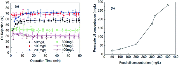 | ||
| Fig. 10 Effect of the crude oil concentration at feed on the (a) rejection and (b) permeate concentration.67 | ||
On the other hand, Shi and co-workers18 developed a free-standing single-walled carbon nanotube (SWCNT) network film as thin as 30 nm for the separation of oil water emulsion. These films are hydrophobic with water contact angle >90° and superoleophilic (extremely oil-absorbent with oil contact angle of 0°). They allow oil to easily permeate through, while simultaneously preventing the water permeation. It is found that an unprecedented high flux of 100![[thin space (1/6-em)]](https://www.rsc.org/images/entities/char_2009.gif) 000 L m−2 h−1 bar−1 can be achieved, i.e., 2–3 orders of magnitude higher than the compared commercial separation membranes, with an excellent oil separation efficiency (>99.95%).18 The high oil separation efficiency can be attributed to two factors. The first factor is related to the nanometer-scale thickness of the SWCNT films which is about 2–3 orders of magnitude smaller than conventional filtration membranes with a similar pore size distribution; another is due to the superoleophilic property of SWCNT films. When emulsion droplets touch the SWCNT film, a de-emulsification process could take place immediately on the film surface due to the strong oil (including surfactants) capturing capability.
000 L m−2 h−1 bar−1 can be achieved, i.e., 2–3 orders of magnitude higher than the compared commercial separation membranes, with an excellent oil separation efficiency (>99.95%).18 The high oil separation efficiency can be attributed to two factors. The first factor is related to the nanometer-scale thickness of the SWCNT films which is about 2–3 orders of magnitude smaller than conventional filtration membranes with a similar pore size distribution; another is due to the superoleophilic property of SWCNT films. When emulsion droplets touch the SWCNT film, a de-emulsification process could take place immediately on the film surface due to the strong oil (including surfactants) capturing capability.
Hsieh and co-workers69 studied the surface properties and oil separation efficiency of carbon fabric (CF) membrane modified with fluorinated CNTs. As compared with the CF membrane without CNTs, the CNTs–CF membrane delivers better separation efficiencies at each different thickness of CFs (see Fig. 11(a)). The separation efficiency of CNTs–CF membrane (with 0.35 cm in thickness) can reach as high as 99.7%. Furthermore, they also found that the thinner the CF membrane, the faster the permeability can be attained (as shown in Fig. 11(b)) and the presence of CNTs is favorable for the permeability at the same thickness of CF membrane. As seen from the figure, CNTs–CF membrane could reach to an oil permeability of 180 L m−2 h−1 bar−1, better than CF membrane without the CNTs (95 L m−2 h−1 bar−1). This could be owing to its low kinetic energy of liquid drops on the membrane surface (Wad) value and high water repellency as shown by the high water contact angle (WCA) (∼165°). In comparison to the SWCNT network film developed by previous studies of Shi et al.,18 the water flux is much lower when CNTs are incorporated with CF membrane, this is probably due to the additional water resistance caused by the CF support which affect the permeate flux performance.
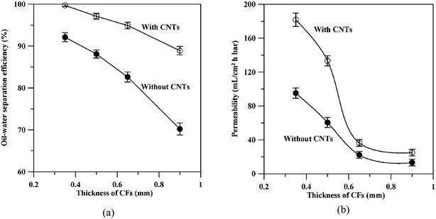 | ||
| Fig. 11 The variation of (a) oil water separation efficiency and (b) permeability with the thickness of CF membrane.69 | ||
The superoleophobicity of membrane surface was further investigated using three different types of liquid droplets, i.e., distilled water, bead sauce, and olive oil and the images are illustrated in Fig. 12. As illustrated in Fig. 12(a)–(c), besides water droplet, the other two types of oil droplets completely wetted the CF surface, indicating the superoleophilic behavior of CF membrane. Without any change in morphology, the fluorinated CF surface exhibited an essential water- and oil-repellency, as shown in Fig. 12(d)–(f). This result reflected that the fluorination treatment had efficiently lowered the surface energy of CF substrate. In contrast, three different liquid droplets displayed same quasi-spherical form on the CNT–CF surface, as demonstrated in Fig. 12(g)–(i). Thus, the fluorinated CF membranes incorporated with CNTs exhibit the highest oil and water repellency.
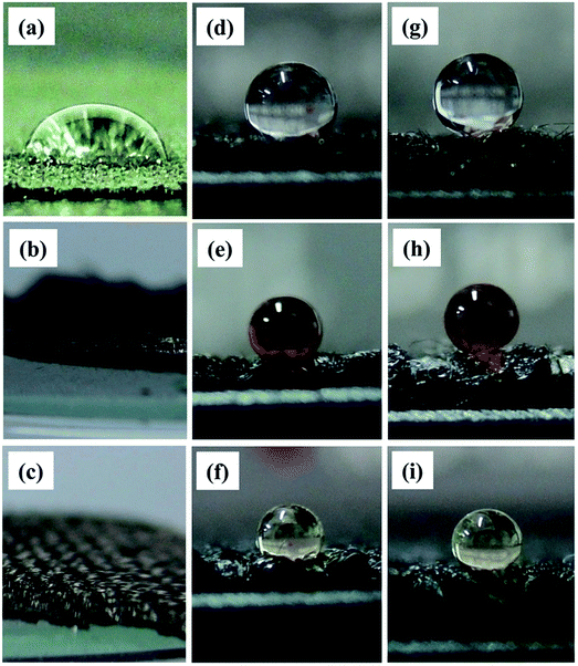 | ||
| Fig. 12 Photographs of different liquid droplets on (a–c) original CFs, (d–f) fluorinated CFs, and (g–i) fluorinated CNT–CF membrane. Herein the top, middle and bottom rows represent water, soya sauce, and olive oil, respectively.69 | ||
Although carbon based membranes are able to achieve very high performance, they are not able to be mass produced due to its relatively high cost in the performance regeneration process induced by the tiny emulsified oil droplets within the surface pores. Moreover, the complicated issue and the environmental impact facing when using additional chemical reagents on membrane cleaning process have to be taken into account. Moreover, a complete assessment on the cost effectiveness in the aspect of energy consumption using carbon based membrane for effective treatment of produced water and the profit generation from valuable oil recovery process must be carefully evaluated prior to the realization of carbon based membrane in oil and gas industries.
6. Conclusion and future outlook
Numerous studies have been performed to design advanced functional nanomaterials and membranes for oil/water separation. Nanotechnology has been gaining popularity in many sectors and the momentum has been increasing in the application of treating oily wastewater as well. The extraordinary properties of the carbon based nanomaterials are able to provide leap forward opportunities to revolutionize traditional oily wastewater treatment. The astonishing properties of graphene oxide, carbon nanotubes and carbon fiber in this review have proven their potential benefits to the real practical application. Further modification on these carbon based nanomaterials to improve the properties and cost-effectiveness shows a bright future of these nanomaterials towards oil related industries. To further enhance their stability and separation efficiency in aggressive and adverse environments, much effort has also been focused on the methods of blending with membranes and enhance the performance of carbon-based membrane particularly in water permeability, oil separation efficiency and antifouling properties. For oily wastewater separation, the most important issue to be addressed is to decrease the attachment of oil droplets on the membrane surface. This can be mitigated by surface modification method in which hydrophilic or oleophobic materials are immobilized onto the membrane surface either by chemical reaction or physical adsorption to provide a stable fouling resistance layer. The introduced hydrophilic layer might form an additional hydrated layer to prevent the fouling of oil droplets and allow fouled oil to be easily removed during the cleaning process. In addition to oil droplets, membrane fouling caused by the adsorption of other organic molecules such as surfactants, remains a problem but is often overlooked. Nevertheless, the impacts of key operating parameters such as cross flow velocity, operating pressure, oil concentration and pH, might also contribute to the deterioration of membrane performance. More research is still required to resolve the aforementioned issues as well as to enhance the performance efficiency, reliability and stability of carbon-based membrane for real industrial implementation. Last but not least, it is recommended that advanced pretreatment stage such as photocatalytic oxidation, flotation, gravity separation, flocculation prior to membrane filtration might be advantageous. Although it might take years to resolve the remaining challenges in this field, it appears certain that carbon-based membranes are potential in dealing with a large variety of industrial oily wastewater applications in the future.Acknowledgements
The authors would like to thank Kuwait Foundation for the Advancement Sciences (KFAS) for their financial support through Project No. P31475EC01.References
- A. Fakhru'l-Razi, A. Pendashteh, L. C. Abdullah, D. R. A. Biak, S. S. Madaeni and Z. Z. Abidin, J. Hazard. Mater., 2009, 170, 530–551 CrossRef PubMed.
- Y. Zhu, D. Wang, L. Jiang and J. Jin, NPG Asia Mater., 2014, 6, e101 CrossRef CAS.
- L. Bai, N. Bossa, F. Qu, J. Winglee, G. Li, K. Sun, H. Liang and M. R. Wiesner, Environ. Sci. Technol., 2017, 51, 253–262 CrossRef CAS PubMed.
- A. Baji, Y.-W. Mai, S.-C. Wong, M. Abtahi and P. Chen, Compos. Sci. Technol., 2010, 70, 703–718 CrossRef CAS.
- O. Bakajin, A. Noy, F. Fornasiero, C. P. Grigoropoulos, J. K. Holt, J. B. In, S. Kim and H. G. Park, Nanofluidic Carbon Nanotube Membranes: Applications for Water Purification and Desalination, in Nanotechnology Applications for Clean Water, Elsevier Inc., 2009, pp. 77–93 Search PubMed.
- Y. Cao, N. Liu, C. Fu, K. Li, L. Tao, L. Feng and Y. Wei, ACS Appl. Mater. Interfaces, 2014, 6, 2026–2030 CAS.
- S. Gupta and N.-H. Tai, J. Mater. Chem. A, 2016, 4, 1550–1565 CAS.
- A. K. Kota, G. Kwon, W. Choi, J. M. Mabry and A. Tuteja, Nat. Commun., 2012, 3, 1025 CrossRef PubMed.
- B. Li, X. Liu, X. Zhang, J. Zou, W. Chai and J. Xu, J. Appl. Polym. Sci., 2015, 132, 41821–41828 Search PubMed.
- J. Liu, X. Li, W. Jia, M. Ding, Y. Zhang and S. Ren, J. Dispersion Sci. Technol., 2016, 37, 1294–1302 CrossRef CAS.
- Q. Ma, H. Cheng, A. G. Fane, R. Wang and H. Zhang, Small, 2016, 12, 2186–2202 CrossRef CAS PubMed.
- Y. Yang, H. Wang, J. Li, B. He, T. Wang and S. Liao, Environ. Sci. Technol., 2012, 46, 6815–6821 CrossRef CAS PubMed.
- S. Gao and J. Jin, in Smart Materials for Advanced Environmental Applications, The Royal Society of Chemistry, 2016, pp. 51–90, 10.1039/9781782622192-00051.
- R. K. Thines, N. M. Mubarak, S. Nizamuddin, J. N. Sahu, E. C. Abdullah and P. Ganesan, J. Taiwan Inst. Chem. Eng., 2017, 72, 116–133 CrossRef CAS.
- M. Padaki, R. Surya Murali, M. S. Abdullah, N. Misdan, A. Moslehyani, M. A. Kassim, N. Hilal and A. F. Ismail, Desalination, 2015, 357, 197–207 CrossRef CAS.
- L. Y. Ng, A. W. Mohammad, C. P. Leo and N. Hilal, Desalination, 2013, 308, 15–33 CrossRef CAS.
- R. Das, M. E. Ali, S. B. A. Hamid, S. Ramakrishna and Z. Z. Chowdhury, Desalination, 2014, 336, 97–109 CrossRef CAS.
- Z. Shi, W. Zhang, F. Zhang, X. Liu, D. Wang, J. Jin and L. Jiang, Adv. Mater., 2013, 25, 2422–2427 CrossRef CAS PubMed.
- Z. Xue, Y. Cao, N. Liu, L. Feng and L. Jiang, J. Mater. Chem. A, 2014, 2, 2445–2460 CAS.
- U. Paul, D. Fragouli, I. Bayer and A. Athanassiou, Polymers, 2016, 8, 52 CrossRef.
- F. Zhang, W. B. Zhang, Z. Shi, D. Wang, J. Jin and L. Jiang, Adv. Mater., 2013, 25, 4192–4198 CrossRef CAS PubMed.
- M. Jin, S. Li, J. Wang, Z. Xue, M. Liao and S. Wang, Chem. Commun., 2012, 48, 11745–11747 RSC.
- L.-P. Xu, J. Peng, Y. Liu, Y. Wen, X. Zhang, L. Jiang and S. Wang, ACS Nano, 2013, 7, 5077–5083 CrossRef CAS PubMed.
- Z. Dang, L. Liu, Y. Li, Y. Xiang and G. Guo, ACS Appl. Mater. Interfaces, 2016, 8, 31281–31288 CAS.
- J. Yang, Y. Tang, J. Xu, B. Chen, H. Tang and C. Li, Surf. Coat. Technol., 2015, 272, 285–290 CrossRef CAS.
- J. Li, L. Yan, H. Li, J. Li, F. Zha and Z. Lei, RSC Adv., 2015, 5, 53802–53808 RSC.
- C.-F. Wang, F.-S. Tzeng, H.-G. Chen and C.-J. Chang, Langmuir, 2012, 28, 10015–10019 CrossRef CAS PubMed.
- C. Xiao, L. Si, Y. Liu, G. Guan, D. Wu, Z. Wang and X. Hao, J. Mater. Chem. A, 2016, 4, 8080–8090 CAS.
- J. Yang, Z. Zhang, X. Xu, X. Zhu, X. Men and X. Zhou, J. Mater. Chem., 2012, 22, 2834–2837 RSC.
- C.-C. Chang, K. W. Kolewe, Y. Li, I. Kosif, B. D. Freeman, K. R. Carter, J. D. Schiffman and T. Emrick, Adv. Mater. Interfaces, 2016, 3, 1500521 CrossRef PubMed.
- J. Li, H. M. Cheng, C. Y. Chan, P. F. Ng, L. Chen, B. Fei and J. H. Xin, RSC Adv., 2015, 5, 51537–51541 RSC.
- B. Wang and Z. Guo, Chem. Commun., 2013, 49, 9416–9418 RSC.
- S. Mun, E. A. Decker and D. J. McClements, Langmuir, 2005, 21, 6228–6234 CrossRef CAS PubMed.
- S. Jamaly, A. Giwa and S. W. Hasan, J. Environ. Sci., 2015, 37, 15–30 CrossRef PubMed.
- L. Zhang, J. Gu, L. Song, L. Chen, Y. Huang, J. Zhang and T. Chen, J. Mater. Chem. A, 2016, 4, 10810–10815 CAS.
- M. Namasivayam and J. Shapter, J. Compos. Mater. DOI:10.1177/0021998317692398.
- M. Sarno, A. Tamburrano, L. Arurault, S. Fontorbes, R. Pantani, L. Datas, P. Ciambelli and M. S. Sarto, Carbon, 2013, 55, 10–22 CrossRef CAS.
- M. Elimelech and W. A. Phillip, Science, 2011, 333, 712–717 CrossRef CAS PubMed.
- B. Corry, J. Phys. Chem. B, 2008, 112, 1427–1434 CrossRef CAS PubMed.
- J. Gu, P. Xiao, L. Zhang, W. Lu, G. Zhang, Y. Huang, J. Zhang and T. Chen, RSC Adv., 2016, 6, 73399–73403 RSC.
- J. Saadati and M. Pakizeh, J. Taiwan Inst. Chem. Eng., 2017, 71, 265–276 CrossRef CAS.
- A. Moslehyani, A. F. Ismail, M. H. D. Othman and T. Matsuura, Desalination, 2015, 363, 99–111 CrossRef CAS.
- S. Maphutha, K. Moothi, M. Meyyappan and S. E. Iyuke, Sci. Rep., 2013, 3, 1509 Search PubMed.
- A. K. Geim and K. S. Novoselov, Nat. Mater., 2007, 6, 183–191 CrossRef CAS PubMed.
- J.-H. Ahn, B. H. Hong, F. Torrisi, J. N. Coleman, J. Liu, S. Böhm, M. Drndić, K. Kostarelos, K. S. Novoselov and E. J. Siochi, Nat. Nanotechnol., 2014, 9, 737–737 Search PubMed.
- K. Jayaramulu, K. K. R. Datta, C. Rösler, M. Petr, M. Otyepka, R. Zboril and R. A. Fischer, Angew. Chem., Int. Ed., 2016, 55, 1178–1182 CrossRef CAS PubMed.
- D. Li, M. B. Muller, S. Gilje, R. B. Kaner and G. G. Wallace, Nat. Nanotechnol., 2008, 3, 101–105 CrossRef CAS PubMed.
- N. L. Le, P. H. H. Duong and S. P. Nunes, in Reference Module in Chemistry, Molecular Sciences and Chemical Engineering, Elsevier, 2017, DOI:10.1016/B978-0-12-409547-2.12275-9.
- G. Wang, B. Wang, J. Park, J. Yang, X. Shen and J. Yao, Carbon, 2009, 47, 68–72 CrossRef CAS.
- J. A. Prince, S. Bhuvana, V. Anbharasi, N. Ayyanar, K. V. K. Boodhoo and G. Singh, Water Res., 2016, 103, 311–318 CrossRef CAS PubMed.
- J. Zhang, Q. Xue, X. Pan, Y. Jin, W. Lu, D. Ding and Q. Guo, Chem. Eng. J., 2017, 307, 643–649 CrossRef CAS.
- X. Hu, Y. Yu, J. Zhou, Y. Wang, J. Liang, X. Zhang, Q. Chang and L. Song, J. Membr. Sci., 2015, 476, 200–204 CrossRef CAS.
- Y. Huang, H. Li, L. Wang, Y. Qiao, C. Tang, C. Jung, Y. Yoon, S. Li and M. Yu, Adv. Mater. Interfaces, 2015, 2, 1400433 CrossRef.
- K. C. Ho, Y. H. Teow, W. L. Ang and A. W. Mohammad, Sep. Purif. Technol., 2017, 177, 337–349 CrossRef CAS.
- A. Zurutuza and C. Marinelli, Nat. Nanotechnol., 2014, 9, 730–734 CrossRef CAS PubMed.
- Y. Jiang, P. Biswas and J. D. Fortner, Environ. Sci.: Water Res. Technol., 2016, 2, 915–922 CAS.
- H. Zhu, S. Qiu, W. Jiang, D. Wu and C. Zhang, Environ. Sci. Technol., 2011, 45, 4527–4531 CrossRef CAS PubMed.
- Y. Shang, Y. Si, A. Raza, L. Yang, X. Mao, B. Ding and J. Yu, Nanoscale, 2012, 4, 7847–7854 RSC.
- Y. Si, Q. Fu, X. Wang, J. Zhu, J. Yu, G. Sun and B. Ding, ACS Nano, 2015, 9, 3791–3799 CrossRef CAS PubMed.
- G. Deschamps, H. Caruel, M.-E. Borredon, C. Albasi, J.-P. Riba, C. Bonnin and C. Vignoles, Environ. Sci. Technol., 2003, 37, 5034–5039 CrossRef CAS PubMed.
- X. Tang, Y. Si, J. Ge, B. Ding, L. Liu, G. Zheng, W. Luo and J. Yu, Nanoscale, 2013, 5, 11657–11664 RSC.
- Z.-M. Huang, Y. Z. Zhang, M. Kotaki and S. Ramakrishna, Compos. Sci. Technol., 2003, 63, 2223–2253 CrossRef CAS.
- K. Wei, H.-K. Kim, N. Kimura, H. Suzuki, H. Satou, K.-H. Lee, Y.-H. Park and l.-S. Kim, J. Nanosci. Nanotechnol., 2013, 13, 1–6 CrossRef.
- H. Liu, C.-Y. Cao, F.-F. Wei, P.-P. Huang, Y.-B. Sun, L. Jiang and W.-G. Song, J. Mater. Chem. A, 2014, 2, 3557–3562 CAS.
- M. H. Tai, P. Gao, B. Y. L. Tan, D. D. Sun and J. O. Leckie, ACS Appl. Mater. Interfaces, 2014, 6, 9393–9401 CAS.
- C. Li, C. Song, P. Tao, M. Sun, Z. Pan, T. Wang and M. Shao, Sep. Purif. Technol., 2016, 168, 47–56 CrossRef CAS.
- Y. Wu, X. Zhang, S. Liu, B. Zhang, Y. Lu and T. Wang, Sep. Sci. Technol., 2016, 51, 1872–1880 CrossRef CAS.
- L. Yu, M. Han and F. He, Arabian J. Chem., http:// dx.doi.org/10.1016/j.arabjc.2013.07.020 Search PubMed.
- C.-T. Hsieh, J.-P. Hsu, H.-H. Hsu, W.-H. Lin and R.-S. Juang, Surf. Coat. Technol., 2016, 286, 148–154 CrossRef CAS.
| This journal is © The Royal Society of Chemistry 2017 |
