 Open Access Article
Myristic acid-hybridized diatomite composite as a shape-stabilized phase change material for thermal energy storage
Jie Han * and
Songyang Liu
School of Mining Engineering, Liaoning Shihua University, Fushun 113001, China. E-mail: 2002aige@sina.com; Tel: +86-024-56863306
First published on 20th April 2017
Abstract
This study was aimed at developing a shape-stabilized composite phase-change material (PCM) for thermal energy storage. Raw diatomite was first purified via thermal treatment and acid-leaching to enhance the adsorption capacity of the PCM. The composite PCM was fabricated using myristic acid (MA) to hybridize diatomite via the vacuum impregnation method. Activated carbon (AC) was added to enhance the stability and conductivity of the composite PCM, and it could also be used to prevent the leakage of MA from the supporting materials. The maximum loading capacity and melting enthalpy of MA/H-diatomite-2 reached 72% and 124.3 J g−1, respectively, and its thermal conductivity was as high as 0.58 W (m K)−1. Note that the introduction of AC obviously reduced the melting and freezing periods and enhanced the heat transfer of the composite PCM. Furthermore, MA/H-diatomite-2 exhibits excellent thermal reliability after 200 cycles and could be potentially used in thermal energy storage systems.
Introduction
With the development of modern industry and agriculture, the consumption of energy fuels, such as oil, gases or coal, is dramatically increasing. On the one hand, energy is urgently needed for economic development. On the other hand, limited and unrecoverable energy sources, especially fossil fuels such as oil and coal, cannot provide an adequate supply of energy. Consequently, it is important to fully and effectively utilize the existing energy resources.1–6 A number of different energy systems, such as thermal energy storage (TES) systems, have been designed to improve the energy utilization rate.7–9 Sensible heat thermal energy storage (SHTES) and latent heat thermal energy storage (LHTES) have been proven as promising and efficient techniques for energy conservation enhancement.10–12 The use of PCMs in LHTES has become a satisfactory choice because of their advantages such as chemical stability, safety, constant temperature during the phase change process, and reasonable price.13,14PCMs can be any materials that have the ability to store and release thermal energy from the melting to freezing process. When the outer environment temperature is higher than the melting temperature of the PCM, it absorbs heat; otherwise, the chemical bonds of the PCM would be destroyed. When the environment temperature is reduced to less than the freezing temperature of the PCM, it releases heat and returns to the solid state.15 To date, many PCMs have been studied such as organic, inorganic, and eutectic PCMs.16–18 Organic PCMs are extensively used because of their high latent heat, appropriate phase-change temperature, small volume change in the phase change process, and commercial availability at a reasonable cost.19,20 MA is a promising organic PCM and widely studied by previous researchers.21,22 As a prospective solid–liquid PCM, myristic acid exhibits many advantages such as high energy storage capacity, non-toxicity, non-flammability, little or no sub-cooling, low vapour pressure, and good thermal and chemical reliability. However, in addition to these desirable characteristics, two disadvantages limit the applications of MA and MA-based PCMs. One is the leakage of the liquid phase above the melting temperature and other is their relatively low thermal conductivity. To solve the abovementioned problems, a large amount of porous inorganic materials or silicate minerals such as bentonite,23,24 kaolinite,25 halloysite,26,27 diatomite,28,29 and expanded perlite,30,31 have been studied to support the PCMs.
Diatomite is a type of natural amorphous siliceous mineral obtained from geological deposits and has many advantages such as highly porous structure, excellent adsorption capacity, chemical stability, and relatively low price. Both the chemical composition and the physical structure of diatomite make it suitable for many scientific and industrial purposes. Diatomite is used in many fields as a filtering agent, building material, catalyst carrier, and ingredient in medicines. Moreover, diatomite is abundantly available in Chinese markets. In recent years, shape-stabilized PCMs have become a hot spot of research, which can maintain a solid shape even when the temperature is higher than the melting point of the PCM itself. It has been confirmed that this method can be an effective way to resolve the leakage and low thermal conductivity problems of composite PCMs.
In this study, diatomite was first purified by thermal treatment and acid-leaching to make it more suitable as an MA carrier. Subsequently, diatomite-based composite PCMs were prepared through the vacuum impregnation method. AC was used to improve the stability and conductivity of the composite PCM, and it could also be used to prevent MA from leaking out of the supporting materials. Moreover, the microstructure, phase change performance, thermal conductivity, thermal stability, and reliability of the composite PCM were systematically investigated.
Experimental
Materials
The diatomite samples (SBET = 16.54 m2 g−1) used herein were obtained from Jilin, China. The typical chemical composition is (mass%): SiO2, 94% and Al2O3, 3.1%. To enhance the adsorption capacity of the PCM, diatomite was well purified by thermal treatment and acid-leaching. First, diatomite samples were thermally treated at 600 °C for 2 h. The obtained powders were then subjected to an acid-leaching process with 2 M HCl solution at 85 °C for 6 h and were named H-diatomite. After this, the precipitate was recovered by sedimentation, followed by washing three times with distilled water. Analytically pure MA was supplied by Sinopharm Chemical Reagent Co., Ltd. Hydrochloric acid was purchased from Zhuzhou Chemical Industry Institute and distilled water was made in the laboratory. AC was obtained from Beijing Green Environmental Protection Co., Ltd., China.Characterization
X-ray diffraction (XRD) analysis of the samples was carried out via a Rigaku D/max-2550VBR + 18 kW powder diffractometer using Cu Kα radiation (λ = 1.5418 Å) in the 2θ range from 5° to 80°. Fourier transform infrared spectroscopy (FTIR) spectra of the samples (KBr pellets) were obtained via a Nicolet 5700 spectrophotometer. Scanning electron microscopy (SEM) was performed using a scanning electron microscope (FEI Quanta-200) system to observe the surface morphology of the samples, and the samples were coated with conductive gold before carrying out the measurements. Transmission electron microscopy (TEM) images were obtained using a JEOL JEM-2100F electron microscope. The BET specific surface area of the raw diatomite was measured using an ASAP unit. Photomicrographs of the PCM composites were obtained by a Leica DFC480 photomicroscope.The thermal storage performances of the samples were measured by a differential scanning calorimeter (DSC, TA instruments DSC Q10) at the heating rate of 5 °C min−1. The maximum loading and thermal stability of the samples were evaluated by a TGA Q50 from 30 °C to 500 °C at 10 °C min−1 under a nitrogen flow. To evaluate the thermal storage/release performance of the composite PCM, thermal cycling experiments were conducted using identical test tubes. First, the test tubes were placed in a thermostatic water bath (30 °C) to achieve stability. Then, the test tubes were placed inside another thermostatic water bath (80 °C). After the temperature reached 80 °C, the test tubes were again placed in the thermostatic water bath (30 °C). The reliability of the samples was studied via 200 repeated thermal (melting/solidifying) cycling tests. The thermal conductivities of the samples were measured using a TC 3000 thermal conductivity meter.
Preparation of phase-change diatomite
The MA/H-diatomite composite was synthesized via the vacuum impregnation method. H-diatomite with different mass fractions (10, 20, 30, and 40 wt%) was prepared and added to a conical flask, which was connected to a vacuum pump through a backflow prevention device. First, the system was placed under vacuum at 0.1 MPa for 10 min, and subsequently the conical flask was placed in a thermostatic water bath at 85 °C for 30 min. After cooling, the reactants were placed in an 80 °C water bath to remove the excess MA and finally the MA/H-diatomite composite was obtained. MA/H-diatomite-1 was prepared via the vacuum impregnation method. Then, 20 g H-diatomite, 80 g MA, and 5 g AC were added to a conical flask. A device was added between the conical flask and vacuum pump to prevent back suction. The sample was evacuated to −0.1 MPa for 10 min first, and then the conical flask was placed in a thermostatic water bath at 85 °C for 30 min. The vacuum pump was switched off and air was allowed to enter the system such that to force MA to penetrate into H-diatomite, while the composite was ultrasonically heated at 80 °C for 5 min. After cooling, the composite was placed in a water bath at 80 °C for 24 h to remove the superfluous MA by the thermal filtration method and the composite was named MA/H-diatomite-1. MA/H-diatomite-2 was also prepared via the vacuum impregnation method. Then, 20 g H-diatomite, 80 g MA, and 10 g AC were added to a conical flask. The experimental process was the same as that of MA/H-diatomite-1. Finally, the composite was obtained and named MA/H-diatomite-2.Results and discussion
The chemical compatibility of MA and the supporting materials was investigated via XRD and FTIR analysis. Fig. 1 shows the XRD patterns of diatomite, H-diatomite, MA, MA/H-diatomite, MA/H-diatomite-1, and MA/H-diatomite-2 composite. As can be seen from Fig. 1, diatomite has the typical non-crystalline diffraction peaks of SiO2. Moreover, the quartz crystalline phase is also found. It can be clearly seen that there is no crystal structure variation in H-diatomite after the heat and acid treatment compared with the raw diatomite. Pristine MA has three main diffraction peaks at 2θ = 8.6°, 2θ = 21.9°, and 2θ = 24.6°. After MA was impregnated into the H-diatomite support, the diffraction peaks of MA and the support were observed in the composite, which suggested that MA was successfully loaded into the support. With the introduction of 5% and 10% AC, it can be clearly seen that the crystal structure and crystalline phase of the MA/H-diatomite-1 and MA/H-diatomite-2 composites were not affected. Furthermore, the intense and sharp diffraction peaks of MA can be observed in the composite PCMs, which indicated that the impregnation process did not affect the crystal structure of MA.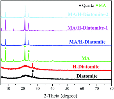 | ||
| Fig. 1 XRD patterns of diatomite, H-diatomite, MA, MA/H-diatomite, MA/H-diatomite-1, and MA/H-diatomite-2. | ||
The compatibility between PCM substrate, AC, and diatomite was determined via FTIR analysis. Fig. 2 demonstrates the FTIR spectra of diatomite, H-diatomite, MA, AC, MA/H-diatomite, MA/H-diatomite-1, and MA/H-diatomite-2 composite. The raw diatomite possesses the main adsorption bands at 1093 and 792 cm−1. The band at 1093 cm−1 represents the siloxane (–Si–O–Si–) group stretching. The peak at 792 cm−1 represents the SiO–H vibration. The chemical structure of H-diatomite remains unchanged after the heat and acid treatment. In the pure MA spectrum, the bands at 2919 and 2850 cm−1 are assigned to the typical stretching vibrations of C–H. In addition, the band at 1701 cm−1 corresponds to the stretching vibration of C![[double bond, length as m-dash]](https://www.rsc.org/images/entities/char_e001.gif) O. In the spectrum of AC, the band at 2918 cm−1 is associated with the stretching vibration of C–H. In addition, the absorption band at approximately 1091 cm−1 is due to the C–O stretching vibration. Moreover, we found that the primary functional groups of H-diatomite, AC, and MA also appeared in the spectra of the MA/H-diatomite, MA/H-diatomite-1, and MA/H-diatomite-2 composites, which means that there was no chemical interaction between the supporting materials, AC, and MA.
O. In the spectrum of AC, the band at 2918 cm−1 is associated with the stretching vibration of C–H. In addition, the absorption band at approximately 1091 cm−1 is due to the C–O stretching vibration. Moreover, we found that the primary functional groups of H-diatomite, AC, and MA also appeared in the spectra of the MA/H-diatomite, MA/H-diatomite-1, and MA/H-diatomite-2 composites, which means that there was no chemical interaction between the supporting materials, AC, and MA.
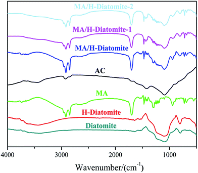 | ||
| Fig. 2 FTIR spectra of diatomite, H-diatomite, MA, AC, MA/H-diatomite, MA/H-diatomite-1, and MA/H-diatomite-2. | ||
Fig. 3 shows the microstructure of raw diatomite and H-diatomite. The morphology of diatomite is mainly composed of disc-like structures, which can be clearly observed in Fig. 3(a). As can be seen from Fig. 3(b) and its inset, H-diatomite retains the characteristic disc-like morphology after heat and acid treatment with an outer pore diameter of ∼550–650 nm and inner diameter of ∼250–350 nm. In Fig. 3(c), many pores on the diatomite powder can be clearly observed, which indicates its high porosity as expected. However, numerous impurities exist on the surface of the raw diatomite. Moreover, the majority of pores on the surface of diatomite are blocked by these impurities. It can be seen from Fig. 3(d) that there are less impurities after the heat and acid treatment. Moreover, the clogged pores are dredged to a variable extent. Moreover, TEM analysis was also used to confirm the observations acquired from SEM. From Fig. 3(e), it is clear that there are numerous macropores and mesopores in the middle and peripheral area of the diatomite disk, which is consistent with the SEM observations. However, most of the macropores are blocked by impurities. In Fig. 3(f), many pores can be clearly seen and the morphology of the porous structure is retained after the heat and acid treatment. Consequently, we concluded that calcination and acid leaching is an effective modification method to dredge the pores on diatomite.
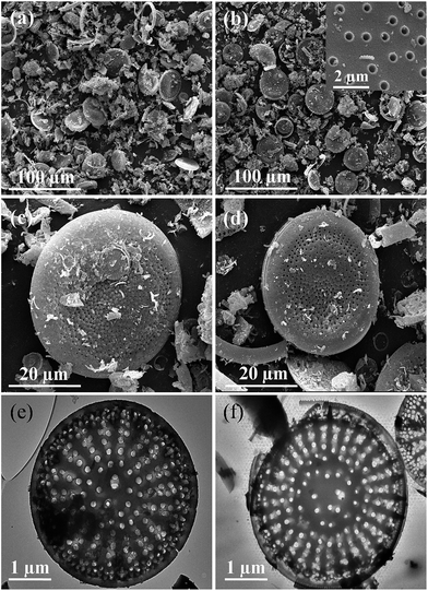 | ||
| Fig. 3 SEM images of (a and c) diatomite and (b and d) H-diatomite. TEM images of (e) diatomite and (f) H-diatomite. | ||
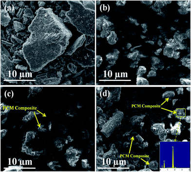
Fig. 4 shows the morphology of AC, MA/H-diatomite, MA/H-diatomite-1, and MA/H-diatomite-2. It can be seen from Fig. 4(a) that AC has an irregular shape with many tiny holes and the particle size distribution is not uniform. After coating with MA, the surface of H-diatomite was completely covered by MA (Fig. 4(b)). However, the microstructure of the MA/H-diatomite particles can hardly be observed, and the relative supporting effect of H-diatomite declined. With the introduction of 5% AC, it can be clearly observed that a few MA/H-diatomite-1 composites demonstrated the disc-like structure, as shown in Fig. 4(c). Since the number of phase-change diatomite is small, it may affect the stability of the composite PCMs. With the addition of an increasing amount of AC, the number of shape-stabilized phase-change diatomite gradually increased, as shown in Fig. 4(c) and (d). As shown in Fig. 4(d), MA does not leak from the surface of the composite when MA is in the melting state because the hot spot made by the electric beam makes the investigated PCM locally melt during SEM observations. Note that when the addition of AC increases to 10% (Fig. 4(d)), most of the microstructure of the MA/H-diatomite-2 composite is clearly observed. MA was uniformly dispersed in H-diatomite with no chemical interaction. In addition, the inset in Fig. 4(d) shows the EDS image of MA/H-diatomite-2, and it also confirms that MA has been successfully loaded within the H-diatomite-2 support. We may draw the conclusion that the addition of AC (10%) can prevent the leakage of MA and form the shape-stabilized composite PCM, which could improve its stability and reliability in long term utilization.
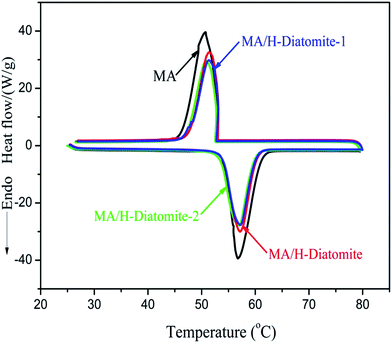
The phase-change properties (latent heat and onset temperature) of MA and the composites were determined by DSC analysis. Fig. 5 shows the DSC curves of MA and other three composite PCMs, and the corresponding data of thermal properties are summarized in Table 1. The curve of MA demonstrates a melting temperature (Tm) at 53.93 °C and a solidifying temperature (Ts) at 53.03 °C. The enthalpy of melting (ΔHm) and solidifying (ΔHs) of MA are 179.5 and 173.6 J g−1, respectively. In comparison with MA, the latent enthalpies of melting and solidifying for the other three composites MA/H-diatomite, MA/H-diatomite-1, and MA/H-diatomite-2 decrease to a certain degree, according to their DSC curves. No significant difference in the phase change enthalpy and temperature was observed between the three PCMs (Table 1). It seems that the MA/H-diatomite-2 composite melts at 53.62 °C with an enthalpy of 124.3 J g−1 and solidifies at 53.33 °C with an enthalpy of 119.4 J g−1 when the maximum loading of MA is 72%, according to the TG test. The actual latent heat values of the composite are lower than the theoretical values (for MA/H-diatomite-2, ΔHm = 179.5 J g−1 × 72% = 129.2 J g−1, and ΔHf = 173.6 J g−1 × 72% = 124.9 J g−1). The reduction in the enthalpy of the PCMs could be ascribed to the following reason: the crystal arrangement and orientation of the MA molecular chains were restricted by the drag and steric effects of the nano and mesopores, which resulted in a decline in the regularity of the crystalline regions. Moreover, Table 2 demonstrates the comparison of the latent heats of the shape-stabilized composite PCMs with that of some composite PCMs reported in the literature,15,32–36 and the MA/H-diatomite-2 composite shows obvious advantages over the reported materials. Note that the prepared MA/H-diatomite-2 composite could be a preferential solar thermal energy storage material for low temperature solar-thermal systems.
| Sample | Melting temperature Tm (°C) | Solidifying temperature Ts (°C) | Latent heat of melting Hm (J g−1) | Latent heat of solidifying Hs (J g−1) |
|---|---|---|---|---|
| MA | 53.93 | 53.03 | 179.5 | 173.6 |
| MA/H-diatomite | 53.58 | 52.73 | 126.9 | 122.3 |
| MA/H-diatomite-1 | 53.61 | 52.59 | 124.9 | 119.7 |
| MA/H-diatomite-2 | 53.62 | 53.33 | 124.3 | 119.4 |
| Sample | Melting | Solidifying | Ref. | ||
|---|---|---|---|---|---|
| Tm (°C) | Hm (J g−1) | Ts (°C) | Hs (J g−1) | ||
| Polyethylene 1000/diatomite | 27.7 | 87.1 | 32.2 | 82.2 | 31 |
| Polyethylene 4000/diatomite/AgNPs | 59.83 | 110.7 | 39.54 | 103.3 | 32 |
| Myristic acid/bentonite | 53.2 | 54.5 | 49.4 | 56.5 | 33 |
| Stearic acid/bentonite/graphite | 53.36 | 84.6 | 52.94 | 84.1 | 34 |
| Capric acid/halloysite nanotubes/graphite | 29.56 | 75.4 | 25.4 | 75.4 | 14 |
| Paraffin/halloysite nanotubes/expanded graphite | 57.26 | 104.6 | 54.17 | 104.3 | 35 |
| MA/H-diatomite-2 | 53.62 | 124.3 | 53.33 | 119.4 | This work |
The thermal conductivities of diatomite, MA, MA/H-diatomite, MA/H-diatomite-1, and MA/H-diatomite-2 before and after thermal cycling are given in Table 3. Compared with pristine MA, the thermal conductivity of MA/H-diatomite was enhanced to a certain degree after being supported by diatomite. The thermal conductivity of MA/H-diatomite-2 is 0.58 W (m K)−1, which is 34% and 23% higher than that of MA/H-diatomite and MA/H-diatomite-1, respectively. This means that the introduction of AC improves the thermal conductivity of the composite PCM. However, the rate of increase is not high. Moreover, no obvious change in the thermal conductivity of MA/H-diatomite-2 after 200 cycling test demonstrates its good reliability.
| Sample | Thermal conductivity (W m−1 K−1) |
|---|---|
| Diatomite | 0.36 |
| MA | 0.17 |
| MA/H-diatomite | 0.43 |
| MA/H-diatomite-1 | 0.47 |
| MA/H-diatomite-2 | 0.58 |
| MA/H-diatomite-2 after thermal cycling | 0.57 |
The thermal storage/release properties of MA/H-diatomite, MA/H-diatomite-1, and MA/H-diatomite-2 were estimated by comparison with those of MA. The melting and solidifying curves of MA and the three PCMs are shown in Fig. 6. MA and the three composite PCMs were stabilized at 30 °C at the beginning of the heat storage process. The test results show that the temperature of MA, MA/H-diatomite, MA/H-diatomite-1, and MA/H-diatomite-2 gradually increased with time. It took 645 s for MA to reach the melting point, whereas only 540 s, 420 s, and 330 s for MA/H-diatomite, MA/H-diatomite-1, and MA/H-diatomite-2, respectively. It is evident that the thermal storage efficiency of MA/H-diatomite-2 is much better than that of MA, MA/H-diatomite, and MA/H-diatomite-1. It was difficult for pure MA to reach 80 °C and it took the longest time (2310 s) to reach the equilibrium temperature, whereas MA/H-diatomite, MA/H-diatomite-1, and MA/H-diatomite-2 took 1965 s, 1650 s, and 1320 s to reach the setup temperature (80 °C), respectively. In the thermal release process, it took 960 s for MA to reach the solidifying temperature compared with 480 s, 570 s, and 270 s for MA/H-diatomite, MA/H-diatomite-1, and MA/H-diatomite-2, respectively. By comparing the melting and solidifying time of MA with that of MA/H-diatomite-2, it was observed that the thermal storage and release rates were increased by 1.8 and 3.6 times, respectively, which indicates that the thermal storage/release rates were greatly increased by the introduction of AC and the efficiency of heat transfer was likewise improved.
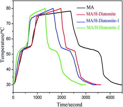 | ||
| Fig. 6 Thermal storage and release curves of MA, MA/H-diatomite, MA/H-diatomite-1, and MA/H-diatomite-2. | ||
To investigate the heat transfer enhancement effect of AC for the composite PCM, photomicrography was used to obtain the morphology and explore the states of MA/H-diatomite, MA/H-diatomite-1, and MA/H-diatomite-2. The disc-like structure of H-diatomite was randomly dispersed and isolated around MA (Fig. 7(a)), which only occupied a less effective volume fraction and thus had difficultly in effectively improving the heat transfer characteristics of the composite PCM. As can be seen from Fig. 7(b), with the introduction of AC (5%), the MA/H-diatomite-1 composite adhered to the flaky AC and they contacted each other, which formed an effective heat transfer structure. Fig. 7(c) shows that most of the particles of MA/H-diatomite-2 closely interacted with each other to form a thermal network structure, which individual MA and MA/H-diatomite-2 effectively supported. This proves that the thermal conductivity and heat transfer characteristics of the composite PCMs increased by the addition of a certain amount of AC. Moreover, the existence of the porous network of AC provides a heat transfer path for the composite PCM and accelerates the phase change speed; this indicates that heat can be more easily transferred from the outside to the inside of MA/H-diatomite-2, which leads to a faster phase change process. Due to the fact that the latent heat of the composite PCM decreased a little after AC was added, MA/H-diatomite with 10% AC was chosen as a satisfactory composite PCM.
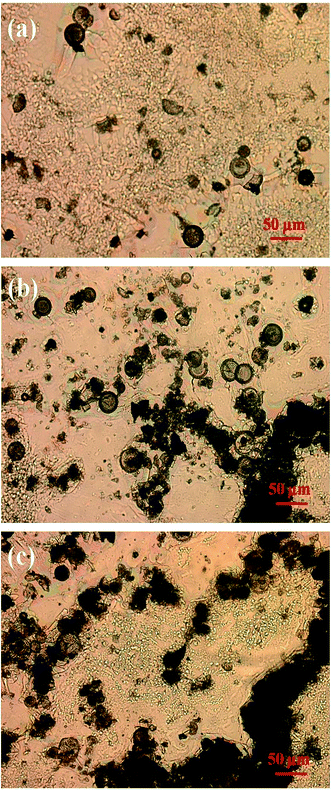 | ||
| Fig. 7 Reflected light microscopy images of (a) MA/H-diatomite, (b) MA/H-diatomite-1, and (c) MA/H-diatomite-2. | ||
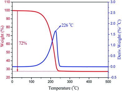
The thermal stability of the composite PCMs is very important for practical applications in thermal regulation. Fig. 8 shows the TG curves and DTG thermograms of the MA/H-diatomite-2 composite PCM. The weight loss process starts at 120 °C and ends at 250 °C with one-step degradation. The sharp weight loss at 226 °C, which is in accordance with the degradation process, can be ascribed to the decomposition of the MA chains. The composite PCM has better thermal stability with the operating-temperature because the degradation of MA occurs over 100 °C. Moreover, the total mass loss of the composite PCM was 72%. The maximum MA loading content of the composite PCM was thus calculated to be 72%.
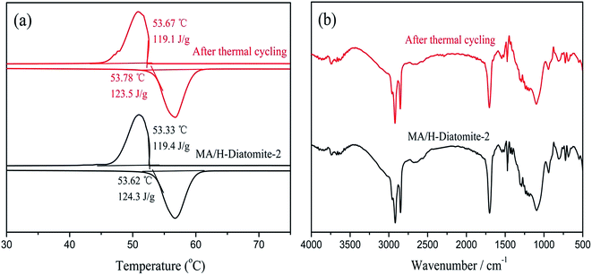
The chemical structure and thermal properties of the composite PCMs should be stable and show a relatively small change after long time cycling. Ensuring the thermal reliability of the composite PCMs through a large number of melting and solidification cycles is a primary prerequisite to determine the suitability of the composites for thermal energy storage applications. The selected materials were subjected to repeated cycle experiments to investigate the phase transition properties of the composite PCM, which include the latent heat of fusion and phase change temperature. A 200-thermal cycling test was conducted to investigate the chemical and thermal reliability of the composite PCM. Fig. 9(a) shows the DSC curves of MA/H-diatomite-2 before and after thermal cycling. It was observed that the melting temperature of MA/H-diatomite-2 changed to 0.16 °C and the value of the melting latent heat changed to 0.8 J g−1. This is a relatively small difference in latent heat, which signifies that the composite PCM has good thermal reliability. The FTIR spectra of MA/H-diatomite-2 before and after thermal cycling are shown in Fig. 9(b). There is no obvious change of the characteristic peaks after thermal cycling, which means that the composite PCM has steady structures. In conclusion, MA/H-diatomite-2 exhibits good thermal reliability and could be potentially used in thermal energy storage systems.
Conclusions
In this study, the shape-stabilized composite MA/H-diatomite-2 was prepared via the vacuum impregnation method. Its structure, morphology, thermal properties, thermal storage and release properties, and thermal reliability were studied in detail. The DSC results indicate that the melting and solidifying temperature of the MA/H-diatomite-2 composite are 53.62 and 53.33 °C, and the latent heats of melting and freezing are 124.3 and 119.4 J g−1, respectively. The addition of AC can help prevent the leakage of MA and enhances the thermal storage and release properties of the composite PCM. The 200 thermal cycling tests results show that the MA/H-diatomite-2 has excellent reliability. The as-prepared MA/H-diatomite-2 might be a promising candidate for building applications, low temperature solar thermal energy application, and thermal management systems due to its large latent heat, suitable phase change temperature, excellent chemical capacities, improved supercooling extent, and high thermal stability and reliability.Acknowledgements
This work was supported by the Liaoning Province Key Laboratory of Petrochemical Environmental Science and Engineering, Research and Development Center for Petrochemical Technology.Notes and references
- J. Wang, M. Yang, F. Lu, K. Jin, L. Tan, Y. Gao, S. Fan, J. Dong and G. Wang, Nano Energy, 2016, 19, 78–87 CrossRef CAS.
- A. Karaipekli and A. Sarι, Sol. Energy Mater. Sol. Cells, 2016, 149, 19–28 CrossRef CAS.
- W. Xu and J. Li, Energy, 2014, 72, 371–380 CrossRef.
- T. Qian, H. Li, X. Min, Y. Deng, M. Guan and L. Ning, Energy Convers. Manage., 2015, 98, 34–45 CrossRef CAS.
- D. Liang, S. Chen, X. Sun, Q. Zhu and A. Li, RSC Adv., 2014, 4, 38535–38541 RSC.
- S. Liu and H. Yang, Appl. Clay Sci., 2014, 101, 277–281 CrossRef CAS.
- T. Khadiran, M. Z. Hussein, Z. Zainal and R. Rusli, Renewable Sustainable Energy Rev., 2016, 57, 916–928 CrossRef CAS.
- C. Chen, W. Liu, H. Wang and K. Peng, Appl. Energy, 2015, 152, 198–206 CrossRef CAS.
- A. Sarι, Energ. Build., 2015, 96, 193–200 CrossRef.
- G. Qi, J. Yang, R. Bao, Z. Liu, W. Yang, B. Xie and M. Yang, Carbon, 2015, 88, 196–205 CrossRef CAS.
- S. Song, L. Dong, S. Chen, H. Xie and C. Xiong, Energy Convers. Manage., 2014, 81, 306–311 CrossRef CAS.
- Y. Yuan, X. Gao, H. Wu, Z. Zhang, X. Cao, L. Sun and N. Yu, Energy, 2017, 119, 817–833 CrossRef.
- R. Li, J. Zhu, W. Zhou, X. Cheng and Y. Li, Appl. Therm. Eng., 2016, 103, 452–458 CrossRef CAS.
- Y. Deng, J. Li, T. Qian, W. Guan, Y. Li and X. Yin, Chem. Eng. J., 2016, 103, 427–435 CrossRef.
- B. Tang, M. Qiu and S. Zhang, Sol. Energy Mater. Sol. Cells, 2012, 105, 242–248 CrossRef CAS.
- L. Feng, P. Song, S. Yan, H. Wang and J. Wang, Thermochim. Acta, 2015, 612, 19–24 CrossRef CAS.
- S. Liu and H. Yang, RSC Adv., 2016, 6, 48033–48042 RSC.
- A. Sharma, V. V. Tyagi, C. R. Chen and D. Buddhi, Renewable Sustainable Energy Rev., 2009, 13, 318–345 CrossRef CAS.
- G. Dheep and A. Sreekumar, Energy Convers. Manage., 2015, 105, 13–19 CrossRef.
- M. K. Rathod and J. Banerjee, Renewable Sustainable Energy Rev., 2013, 18, 246–258 CrossRef CAS.
- D. Wei, S. Han and X. Shen, J. Chem. Thermodyn., 2016, 101, 7–11 CrossRef CAS.
- Y. He, X. Zhang, Y. Zhang, Q. Song and X. Liao, Energ. Build., 2016, 133, 547–558 CrossRef.
- M. Li, Z. Wu, H. Kao and J. Tan, Energy Convers. Manage., 2011, 52, 3275–3281 CrossRef CAS.
- A. Sarι, Energy Convers. Manage., 2016, 117, 132–141 CrossRef.
- C. Li, L. Fu, J. Ouyang, A. Tang and H. Yang, Appl. Clay Sci., 2015, 115, 212–220 CrossRef CAS.
- D. Mei, B. Zhang, R. Liu, H. Zhang and J. Liu, Int. J. Energy Res., 2011, 35, 828–834 CrossRef CAS.
- W. Liang, Y. Wu, H. Sun, Z. Zhu, P. Chen, B. Yang and A. Li, RSC Adv., 2016, 6, 19669–19675 RSC.
- F. Tang, D. Su, Y. Tang and G. Fang, Sol. Energy Mater. Sol. Cells, 2015, 141, 218–224 CrossRef CAS.
- T. Qian, J. Li, H. Ma and J. Yang, Polym. Compos., 2016, 37, 854–860 CrossRef CAS.
- S. Ramakrishnan, J. Sanjayan, X. Wang, M. Alam and J. Wilson, Appl. Energy, 2015, 157, 85–94 CrossRef CAS.
- Z. Lu, J. Zhang, G. Sun, B. Xu, Z. Li and C. Gong, Energy, 2015, 82, 43–53 CrossRef CAS.
- S. Karaman, A. Karaipekli, A. Sarι and A. Biçer, Sol. Energy Mater. Sol. Cells, 2011, 95, 1647–1653 CrossRef CAS.
- T. Qian, J. Li, X. Min, W. Guan, Y. Deng and L. Ning, J. Mater. Chem. A, 2015, 3, 8526–8536 CAS.
- C. Chen, X. Liu, W. Liu and M. Ma, Sol. Energy Mater. Sol. Cells, 2014, 127, 14–20 CrossRef CAS.
- C. Li, L. Fu, J. Ouyang and H. Yang, Sci. Rep., 2013, 3, 1–8 Search PubMed.
- J. Zhang, X. Zhang, Y. Wan, D. Mei and B. Zhang, Sol. Energy, 2012, 86, 1142–1148 CrossRef CAS.
| This journal is © The Royal Society of Chemistry 2017 |

