
 Open Access Article
 This Open Access Article is licensed under a Creative Commons Attribution-Non Commercial 3.0 Unported Licence
Structure-preserved 3D porous silicon/reduced graphene oxide materials as anodes for Li-ion batteries
Keli Zhangab,
Yonggao Xia*a,
Zhengdong Yanga,
Rusheng Fua,
Chengxu Shenab and
Zhaoping Liu *a
*a
aAdvanced Li-ion Battery Engineering Laboratory, Key Laboratory of Graphene Technologies and Applications of Zhejiang Province, Ningbo Institute of Materials Technology & Engineering, Chinese Academy of Sciences, Zhejiang 315201, P. R. China. E-mail: xiayg@nimte.ac.cn; liuzp@nimte.ac.cn; Fax: +86-574-8668-5096; Tel: +86-574-8668-5096
bUniversity of Science and Technology of China, Nanoscience and Technology Institution, Suzhou 215123, P. R. China
First published on 4th May 2017
Abstract
Three dimensional (3D) porous silicon/reduced graphene oxide (Si/rGO) composites with typical networks have suffered damage during electrode preparation, which evidently affects the cycle and rate capabilities of Si/rGO anodes. Here, a controllable evaporation dry method is proposed to fabricate structure-preserved 3D porous Si/rGO anode materials by tuning the pore size distribution of the networks. As a result, after evaporation drying for 3.5 h, the optimal sample of 3D porous Si/rGO anode (denoted as Si–G-3.5) with a pore size of ∼500 nm could preserve its 3D network during the electrode preparation process. While the structures of Si/rGO composites with different drying times (denoted as Si–G-0, Si–G-2.5 and Si–G-4) failed to be preserved. Consequently, The Si–G-3.5 anode exhibits a high reversible specific capacity of 1563 mA h g−1 at 50 mA g−1, 90% capacity retention after 100 cycles and superior rate capability (955 mA h g−1 at 2 A g−1).
Introduction
Lithium-ion batteries (LIBs) used as energy storage devices for portable electronic devices, electric vehicles and power grids have triggered significant demands for the superior performance of materials.1–4 Compared to the conventional graphite anode with low theoretical capacity (372 mA h g−1), silicon (Si), has a high theoretical capacity (4200 mA h g−1), low delithiation potential (∼370 mV vs. Li/Li+), abundant resources, low toxic and environmental compatibility, and has been regarded as the most promising candidate for the next generation anode materials for LIBs.5–7 However, the dramatic volume change (∼300%) of Si anodes during cycling induce severe pulverization, loss of electrical contact, an unstable solid electrolyte interface (SEI) and eventual rapid capacity fading.6,8 Moreover, its poor lithium ion diffusion kinetics and low intrinsic electric conductivity significantly affect rate capability.9To overcome these issues, one strategy is to design versatile Si structures (such as nanoscale Si nanoparticles,10,11 hollow Si12–15 and hierarchical porous structures16,17) which can greatly shorten the Li+ diffusion pathway and reserve additional space to alleviate volume swelling. However, the surfaces of Si nanoparticles are still directly exposed to the electrolyte, leading to the formation of unstable SEI. Another more efficient strategy is to combine nanostructured Si nanoparticles with carbonaceous materials (such as pyrolyzed carbon,18–20 carbon nanofibers,21,22 carbon nanotubes23,24 and graphene25–32) which acts as coating layer and/or framework. The carbonaceous materials not only increase the electrical conductivity but also buffer the volume change and avoid the direct contact between Si and the electrolyte.
Graphene, a two-dimensional material, due to its unique structure and properties, such as excellent electrical conductivity, good flexibility and high mechanical strength have been used to improve the electrochemical performance of Si anodes. Researchers have fabricated various Si/rGO hybrid structures, such as encapsulated Si/rGO,33,34 sandwiched Si/rGO,35,36 Si/rGO film37,38 and Si@void@rGO.39 Recently, the 3D porous Si/rGO composites display superior electrochemical performance, which is contributed to the enhanced electrical conductivity, sufficient reserved space, 3D networks for faster Li+ migration and relatively isolated Si from electrolyte.26,27,40,41 To our knowledge, there are two ways to prepare the electrodes. One is to use Si/rGO monolith as the free-standing material that could keep its original porous structure. Such as, Li et al.26 developed an efficient approach to fabrication of 3D graphene–silicon networks as free-standing anode materials in which Si nanoparticles grown on the surface of GO sheets derived from commercial sponge. Hu et al.41 utilized a facile freeze-drying strategy to fabricate a free-standing graphene-encapsulated silicon nanoparticle aerogel as an anode for lithium ion batteries. The free-standing materials could preserve intact 3D networks because of no slurry making process. Another solution is to employ the current industrial process for slurry. However, Si/rGO composites are subjected to grind and compress in this case. Park et al.40 reported a self-assembly of Si entrapped graphene architecture and exhibited high performance for Li-ion batteries. Zhang et al.27 fabricated pyrolytic carbon-coated Si nanoparticles on elastic graphene framework as anode material for high-performance lithium-ion battery. We notice that the pore sizes of the architectures reported in Park's and Zhang's works are about 20 μm and 10 μm, respectively. As we know, the larger pore structures are easier to be destroyed which could make the interconnected 3D networks destroyed and thus loss of its structural advantages on electrochemical performances. Conversely, the smaller pore structures are easier to be preserved that could ensure its integrity during the electrode preparation. However, Si nanoparticles are subject to aggregate if the porous Si/rGO composites become dense. Thus, the key is to tune the pore sizes and make the interconnected 3D network preserved during the electrode fabricating, which are expected to improve the electrochemical properties of the Si/rGO anode.
Here, we propose a controllable evaporation dry method to tune the pore size distribution of 3D porous Si/rGO composites. During evaporation drying, the surface tension of the trapped solvent on the rGO sheets shrinks the 3D network and decreases the pore sizes, thus the pore sizes can be controlled by regulating the evaporation dry time. A series of 3D porous Si/rGO composites with different pore sizes are designed and fabricated. Consequently, the optimal Si/rGO composite with pore size about 500 nm has the interconnected 3D networks during the electrode preparation and exhibits high reversible specific capacity of 1563 mA h g−1 at 50 mA g−1, 90% capacity retention after 100 cycles and superior rate capability (955 mA h g−1 at 2 A g−1).
Several steps to prepare the specific Si/rGO composites are shown in Fig. 1. Firstly, Si nanoparticles were functionalized by polyvinylpyrrolidone (PVP), which not only made the Si nanoparticles homogeneously dispersed in overlapped graphene sheets but also strengthened the van der Waals interaction between Si and graphene sheets.36 Then, PVP functionalized Si nanoparticles captured in GO sheets were dispersed in the mixed solution of deionized water and ethanol to fabricate the 3D porous Si/rGO hydrogels by solvothermal method. As shown in Fig. 1, the directly freeze-dried Si/rGO hydrogel has large pores which are facile to be destroyed after being grinded and compressed. While after an appropriate time of evaporation drying and following freeze-drying, the Si/rGO hydrogel with contracted network is preserved and also has a well dispersion of Si nanoparticles.
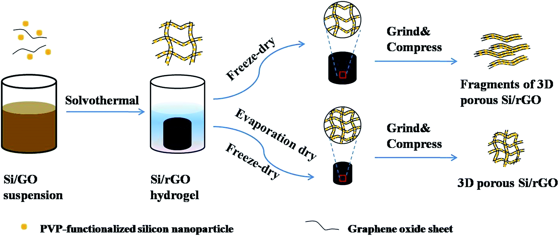 | ||
| Fig. 1 Schematic of the controllable evaporation dry route of 3D porous Si/rGO anode materials. | ||
Experimental
Synthesis of 3D porous Si/rGO hydrogel
Graphene oxide (GO) synthesized by the modified Hummers' method.42 Then, the as-prepared GO was exfoliated and dispersed in deionized water to obtain 6.0 mg ml−1 GO suspension by ultrasonication. Si nanoparticles (100–120 nm, Aladdin) and polyvinylpyrrolidone (PVP, molecular weight of ∼55![[thin space (1/6-em)]](https://www.rsc.org/images/entities/char_2009.gif) 000; Aladdin) were also dispersed in deionized water (mass ratio Si:PVP = 2:1) to obtain a concentration of 5 mg ml−1 suspension using ultrasonication. The GO and PVP–Si suspensions as well as absolute ethyl alcohol were homogeneously mixed at a volume ratio of 1:1:1. And the mixture (90 ml) was placed in a 100 ml Teflon sealed autoclave and then solvothermally treated in a dry oven (180 °C) for 12 h to obtain the Si/rGO hydrogel.
000; Aladdin) were also dispersed in deionized water (mass ratio Si:PVP = 2:1) to obtain a concentration of 5 mg ml−1 suspension using ultrasonication. The GO and PVP–Si suspensions as well as absolute ethyl alcohol were homogeneously mixed at a volume ratio of 1:1:1. And the mixture (90 ml) was placed in a 100 ml Teflon sealed autoclave and then solvothermally treated in a dry oven (180 °C) for 12 h to obtain the Si/rGO hydrogel.
Synthesis of 3D porous Si/rGO anode
In order to verify that the structure changes depended on the time of evaporation drying, a series of hydrogels were dried at 80 °C for 0, 2.5, 3.5 and 4 h. The as-received samples were denoted as Si–G-0, Si–G-2.5, Si–G-3.5 and Si–G-4, respectively. After the heat treatment process with different dry time at 80 °C, the Si–G-x (x = 0, 2.5, 3.5 and 4) were rapidly frozen with liquid nitrogen and undergone the freeze-dryer approach. Then the Si–G-x were pyrolyzed at 800 °C for 2 h under an argon atmosphere with a flow rate of 10 °C min−1, purging for 3 h before the furnace was turned on.Structure characterization
Scanning electron microscopy (SEM) was performed using a Hitachi S4800 (8 kV) and an FEI Quanta FEG 250 (20 kV). Transmission electron microscopy (TEM) was performed in an FEI Tecnai F20 at an accelerating voltage of 200 kV. X-ray power diffraction (XRD) measurements were performed using an AXS D8 Advance Diffractometer (Cu-Kα radiation, 40 mA, 40 kV) from Bruker, Inc. (Germany). Raman spectra analysis was conducted by a Renishaw inVia Reflex Raman spectrometer with excitation by a 532 nm-wavelength laser. Thermal Gravimetric Analysis (TGA) (Pyris Diamond, PerkinElmer, USA) was used to determine carbon content in the Si–G-x composites. TGA testing was performed in air with a temperature range of 30 °C to 800 °C and a ramp rate of 10 °C min−1. The Brunauer–Emmett–Teller (BET) test was determined via a Micromeritics ASAP-2020M nitrogen adsorption apparatus.Electrode fabrication
To prepare the working electrodes, 60 wt% of the Si/rGO composites, 20 wt% Super P as a conductive material, 20 wt% sodium carboxymethylcellulose (CMC) and styrene butadiene rubber (SBR) (CMC:SBR = 3:7, w/w) as binder were homogeneously dispersed in deionized water. Then, the slurry was casted on a copper foil and dried at 120 °C for 12 h in a vacuum oven. The electrodes were cut, pressed and shaped into circular slices with a diameter of 13 mm. The average mass loading of Si–G-0, Si–G-2.5, Si–G-3.5 and Si–G-4 are 0.78 mg cm2, 0.76 mg cm2, 0.74 mg cm2 and 1.65 mg cm2.
Electrochemical measurements
Electrochemical tests were carried out in CR2032-type coin cells. A lithium metal foil was used as the anode, Celgard 2400 microporous membrane was used as separator, and the electrolyte was 1 M LiPF6 dissolved in a mixed solvent of ethylene carbonate (EC) and diethyl carbonate (DEC) (1:1 by volume, Guotai-Huarong New Chemical Material Co., Ltd). The coin-type cells were assembled in an Ar-filled glove box. All the cells were tested under different current densities within the voltage range of 0.005–2.0 V (vs. Li/Li+) using a LAND-CT2001A battery test system (Jinnuo Wuhan Corp., China). Cyclic voltammetry (CV) tests were performed on a Solartron electrochemistry workstation at a scan rate of 0.1 mV s−1 over a potential range of 0.005–2.0 V (vs. Li/Li+) at room temperature. Electrochemical impedance spectroscopies (EIS) were employed to clarify the resistance information by using an electrochemical station (Solartron) in the frequency range from 100 kHz to 0.01 Hz.
Results and discussion
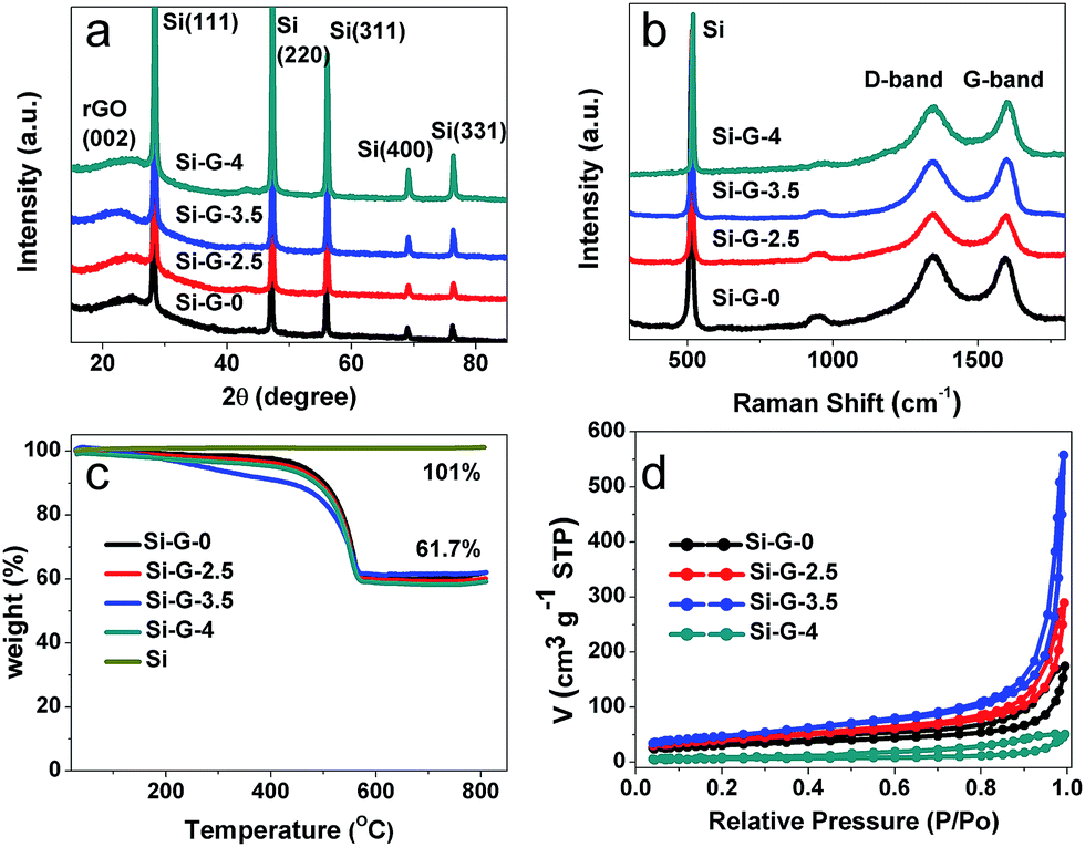
A series of Si/rGO hydrogels were dried at 80 °C for 0 h, 2.5 h, 3.5 h and 4 h (denoted as Si–G-0, Si–G-2.5, Si–G-3.5 and Si–G-4, respectively). Then modified Si/rGO hydrogels with different pore sizes were freeze dryed for 48 h. With the increasing of evaporation dry time, the pores are gradually shrinking, and finally, there are no obvious macropores. The SEM images shown in Fig. 2a–l demonstrate the different pore structures of the synthesized 3D porous Si–G-x (x = 0, 2.5, 3.5 and 4) composites with Si nanoparticles wrapped into the walls of overlapped rGO sheets. Images shown from the left to the right (Si–G-0, Si–G-2.5 and Si–G-3.5) indicate that the pores gradually shrinking from ∼10 μm to ∼500 nm with the evaporation of solvent while the 3D networks are not changed (Fig. 2a–c and e–g). The obtained Si–G-4 shows a much more compact microstructure than others and no obvious macropores can be observed. Meanwhile, Si nanoparticles are aggregated severely in Si–G-4 because of the internal shrinkage force induced by evaporation dry approach (Fig. 2d and h). The prepared Si–G-0, with the pore sizes as large as 10 μm (Fig. 2e), is destroyed after grind and compress processes, leading to the stacking of cracked rGO sheets and breaking of the 3D networks (Fig. 2i). The Si–G-2.5 is also damaged by the same processes (Fig. 2j). From the TEM images of Fig. 3a and Fig. 3b, the poor dispersion of Si nanoparticles also illustrate that larger sizes of pores will result in more severely stacking of the destroyed rGO sheets after the same treatment. When the drying time increases to 3.5 h, the Si–G-3.5 sample is prepared, in which the pore size is ∼500 nm, not only exhibits the 3D porous framework but also displays a homogeneously dispersion of Si nanoparticles even after the same treatment of grind and compress as before. It is also confirmed by the TEM image in Fig. 3c. Furthermore, the 3D porous framework of the Si–G-3.5 in electrode before cycle (Fig. 4a and b) and after 100 cycles (Fig. 4c and d) are mostly kept its original networks, and the Si nanoparticles are well dispersed in rGO nanosheets, which verify the intactness of the Si–G-3.5 after the grind and compress. When the drying times continue increase to 4 h, the solvent is completely removed that the Si–G-4 has been compacted and loses its 3D networks. Consequently, among the four different pore structures of Si/rGO composites, only the Si–G-3.5 that can be prevented from being destroyed during the electrode preparation and has a homogeneously dispersion of Si nanoparticles.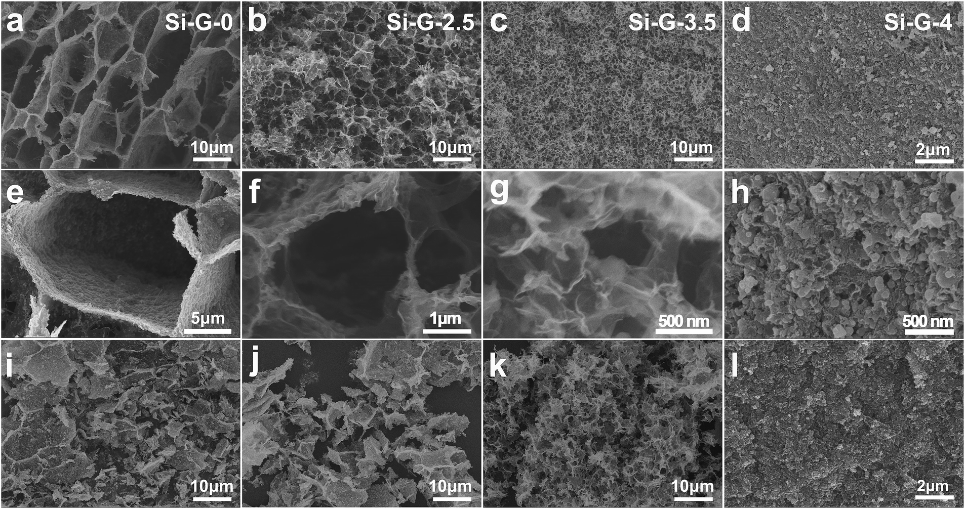 | ||
| Fig. 2 SEM images of Si–G-x composites: (a, e, i) Si–G-0, (b, f, j) Si–G-2.5, (c, g, k) Si–G-3.5 and (d, h, i) Si–G-4. (a–h) Different magnifications before grinding and compressing and (i–l) after grinding and compressing powders of 3D porous Si–G-x (x = 0, 2.5, 3.5 and 4), respectively. | ||
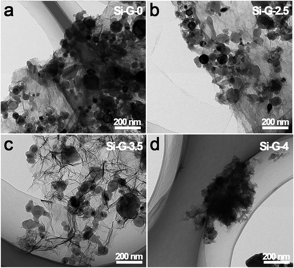 | ||
| Fig. 3 (a–d) TEM images of the synthesized Si–G-x (x = 0, 2.5, 3.5 and 4) after grind and compress. | ||
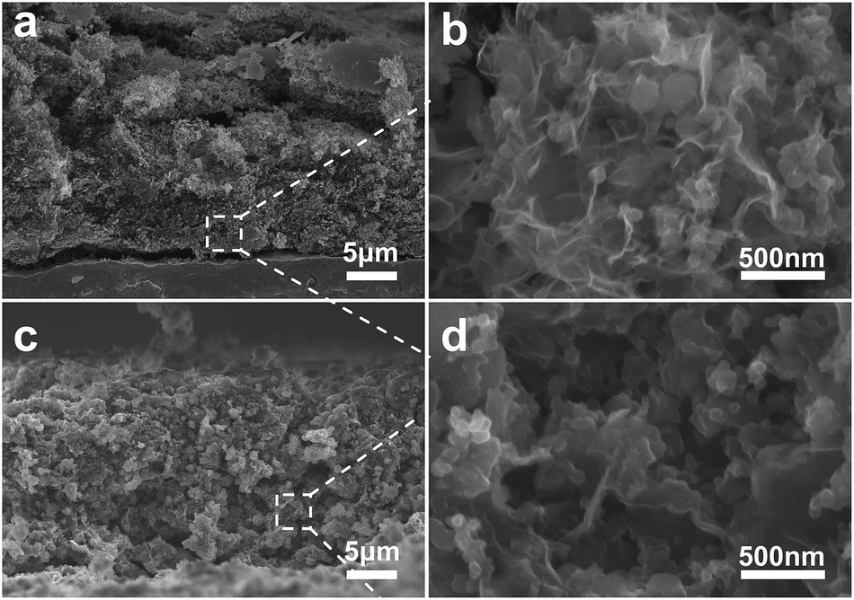 | ||
| Fig. 4 Cross sectional SEM images of the electrode of Si–G-3.5 before cycle (a, b) and after 100 cycles (c, d) at different magnifications. | ||
The X-ray diffraction (XRD) patterns (Fig. 5a) of Si–G-x (x = 0, 2.5, 3.5 and 4) samples showed the characteristic peaks of Si and a broadband centered at 25° of the graphite (002) diffraction peak,43 which indicated that the Si nanoparticles were efficiently embedded during solvothermal process. The diffraction peak intensity of Si has no significant changes from Si–G-0 to Si–G-3 samples. However, the Si–G-4 has an obviously increased peak intensity of Si, indicating that when the solvent was completely removed, the dense Si–G-4 made Si nanoparticles aggregate severely. Raman measurements were carried out to further characterize the reduction degree of reduced graphene oxides in the Si–G-x (Fig. 5b). There are two peaks at ∼520 cm−1 and ∼950 cm−1 which are assigned to Si–Si vibrations.44 The other two wide peaks located at ∼1350 cm−1 and ∼1590 cm−1 in Fig. 5b, respectively, are corresponding to the D and G bands of graphene materials. The ID/IG values of Si–G-x are 1.01, 1.00, 0.99 and 0.98, respectively, which verifies that the surface chemistry of Si–G-x derived by different evaporation time is not remarkable changed.
 | ||
| Fig. 5 (a) The XRD patterns of Si–G-x; (b) the Raman spectra of Si–G-x; (c) the TG curves of Si–G-x and pure Si in air at a heating rate of 5 °C min−1; (d) nitrogen adsorption and desorption isotherms of Si–G-x. (x = 0, 2.5, 3.5 and 4). | ||
Thermogravimetry analysis (TGA) was used to determine the ratio of graphene to silicon within the Si–G-x composites, after removing the majority of the oxygen functional groups from GO during the reduction process. The Si contents of all samples are approximately 61 wt% in the temperature range of 560–800 °C (Fig. 5c). To figure out the specific surface areas of the 3D porous of Si–G-x, nitrogen adsorption–desorption isotherm was performed as shown in Fig. 5d. Based on the Barrett–Joyner–Halenda (BJH) equation, the specific surface areas of Si–G-0, Si–G-2.5, Si–G-3.5 and Si–G-4 are 108.4 m2 g−1, 141.1 m2 g−1, 167.2 m2 g−1 and 22.2 m2 g−1, respectively, which is quite different owing to the different pore structures of the Si/rGO composites. As we know, the creaked graphene sheets could make the π–π stacking and reduce the specific surface areas. Thus the increased specific surface areas also showed that the pores are smaller and the structures are harder to be creaked. While the Si–G-4 is compact and its specific surface area is dramatically decreased.
To further clarify the influence of integrity of as-received 3D porous Si/rGO anode materials on electrochemical properties, the Si–G-x (x = 0, 2.5, 3.5 and 4) were grinded and compressed for electrode preparation and finally were assembled into coin cells. The Si–G-x samples with different pore structures show significantly different electrochemical performances. In the cyclic voltammetry (CV) profiles (Fig. 6a), Si–G-3.5 as a typical example, in the first cycle displays a lithiation peak centered at 0.05 V corresponding to the formation of Li–Si alloy phases,45 and a weak peak at 1.3 V might be related to the reaction of the remaining oxygen in rGO.40 The subsequent cycles exhibit an lithiation peak at 0.2 V, because crystalline silicon was converted to amorphous Si after the initial cycle.46 Two anodic peaks centered at 0.31 V and 0.52 V are corresponding to the dealloying of the Li–Si phase.47
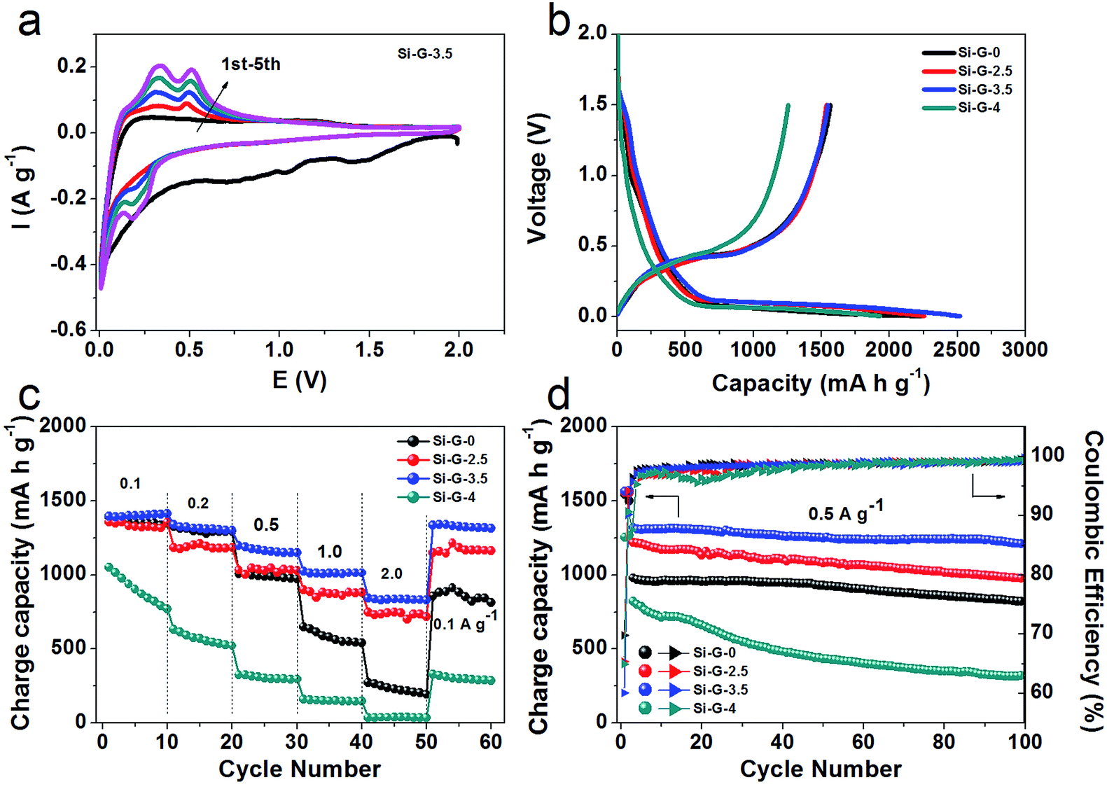 | ||
| Fig. 6 Comparison of the electrochemical performances of Si–G-x (x = 0, 2.5, 3.5 and 4) anodes measured in a voltage range of 0.005–2.0 V vs. Li/Li+. (a) cyclic voltammetry (CV) for the initial five cycles of Si–G-3.5; (b) galvanostatic charge/discharge profiles of Si–G-x electrode for the first cycle at 0.05 A g−1; (c) rate performance at different current densities of Si–G-x; (d) cycling performances and coulombic efficiency of the Si–G-x at 0.5 A g−1 during 100 cycles. All the specific capacities are calculated based on the active materials. | ||
Fig. 6b shows the initial galvanostatic charge/discharge profiles of the Si–G-x at the voltage window of 2.0 to 0.005 V. The obvious plateaus in discharge curves around 1.3 V and 0.05 V and charge curves around 0.5 V of the Si–G-x are well conformed to the CV curves (Fig. 6a). At current density of 0.05 A g−1, the initial specific charge capacities of Si–G-0, Si–G-2.5 and Si–G-4 are calculated to be 1543 mA h g−1, 1551 mA h g−1 and 1254 mA h g−1, respectively, which are lower than 1563 mA h g−1 of Si–G-3.5. In Fig. 6c, Si–G-3.5 is shown to have the highest capacities of all the samples in this study under different current densities (0.1 to 2.0 A g−1). The superior rate capability of the Si–G-3.5 can be attributed to the preserved 3D porous structure during the grinding and compressing. As shown in Fig. 6d, due to the interconnected conductive network and sufficient space for the volume expansion, the Si–G-3.5 shows a higher reversible capacity of 1210 mA h g−1 after 100 cycles at 0.5 A g−1 and higher capacity retention of 90% than the other samples. This comparative analysis highlights the effectiveness of the structure-preserved of Si–G-3.5 in improving the charge capacity and cycling stability of the electrode. The initial coulombic efficiency (CE) of Si–G-0, Si–G-2.5, Si–G-3.5 and Si–G-4 samples are 69.8%, 65.4%, 60.1% and 65%, respectively (Fig. 6d). It should be noted that the lower initial coulombic efficiency (CE) of Si–G-3.5 is not only caused by the formation of SEI layer on Si nanoparticles, but also may be ascribed to the higher surface area of 3D porous graphene foam than the other samples (Fig. 5d). It is reported previously that graphene anodes showed large irreversible capacity in the first cycle, which is associated with the inevitable formation of SEI layer.48,49 Afterward the CE of Si–G-0, Si–G-2.5 and Si–G-3.5 are increased to 98% during the fifth cycle and remain higher than 99% in the following cycles. However, due to the compact architecture and consume more time to activate, the CE of Si–G-4 is unstable in the initial cycles and generally lower than that of other samples. Generally, the CE of Si–G-3.5 remains more stable rising tendency during cycles among the four samples. These indicate that the structure-preserved Si–G-3.5 that own a stable SEI film and a nice electrical contact during cycling despite the drastic dimensional change.
The electrochemical impedance spectra (EIS) of the Si–G-x (x = 0, 2.5, 3.5 and 4) anodes are also compared after two cycles (Fig. 7). The diameter of the depressed semicircle mainly represents the charge transfer resistance, and the angled straight line is related to a diffusion controlled process. Apparently, the diameter of the semicircle for Si–G-3.5 is the smallest among the Si–G-x composites, indicating that the Si–G-3.5 possesses the lowest resistance. The result demonstrates that the excellent cycle and high-rate performance of Si–G-3.5 anode can be attributed to the interconnected 3D network and favorable contact between Si nanoparticles and flexible rGO sheets. Finally, as the electrochemical characterizations shown, the performances of Si–G-0, Si–2.5 and Si–G-3.5 are gradually improved while Si–G-4 sample performs the worst. It can be attributed to the following reasons: the pore sizes of Si–G-0, Si–G-2.5 and Si–G-3.5 gradually decrease by elongating dry time, which result in the preserved structure with better integrity after electrode preparation. The Si–G-0 and Si–G-2.5 samples are entirely or partially destroyed and restacked after electrode preparation, which lengthen the migration pathways of Li+ and make it difficult for electrolyte infiltration. The Si–G-3.5 with preserved 3D networks own not only 3D transport pathway for Li+ and well electrolyte infiltration but also homodisperse of Si nanoparticles, thus performs the best electrochemical properties. However, no obvious pores are observed in Si–G-4 sample because all solvents are removed when drying time increases to 4 h. In this respect, Si–G-4 turns to be compacted and Si nanoparticles aggregate severely, which induce the worst electrochemical performance among the four samples.
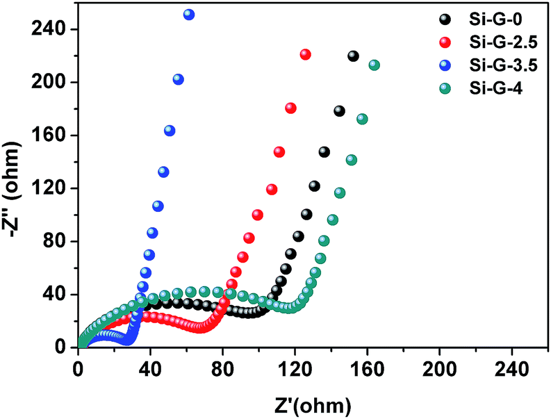 | ||
| Fig. 7 Nyquist plots of Si–G-x (x = 0, 2.5, 3.5 and 4) anodes after two cycles recorded from 100 kHz to 0.01 Hz. | ||
Conclusions
In summary, we have synthesized structure-preserved 3D porous Si/rGO anode materials by controllable evaporation dry method, in which Si nanoparticles are wrapped into the walls of overlapped rGO sheets. After the evaporation drying of 3.5 h, the optimal sample of Si–G-3.5 with pore size of ∼500 nm could be preserved during the electrode preparation. The structure-preserved Si–G-3.5 anode exhibits high reversible specific capacity of 1563 mA h g−1 at 50 mA g−1, 90% capacity retention after 100 cycles and superior rate capability (955 mA h g−1 at 2 A g−1), which is superior to the references. It suggested that the preserved 3D networks own enhanced electrical conductivity, sufficient reserved space and 3D networks for faster Li+ migration, which enhance the electrochemical properties of Si anode materials.Acknowledgements
Financial supports from the National Natural Science Foundation of China (Grant No. 51403227), the National Key Research and Development Program of China (Grant No. 2016YFB0100100), Strategic Priority Research Program of Chinese Academy of Sciences (CAS, Grant No. XDA09010101) and Key Research Program of Chinese Academy of Sciences (Grant No. KGZD-EW-T08) are highly appreciated.Notes and references
- M. T. McDowell, S. W. Lee, W. D. Nix and Y. Cui, Adv. Mater., 2013, 25, 4966 CrossRef CAS PubMed.
- J. M. Tarascon and M. Armand, Nature, 2001, 414, 359 CrossRef CAS PubMed.
- M. Armand and J. M. Tarascon, Nature, 2008, 451, 652 CrossRef CAS PubMed.
- P. G. Bruce, B. Scrosati and J. M. Tarascon, Angew. Chem., Int. Ed., 2008, 47, 2930 CrossRef CAS PubMed.
- M. S. Whittingham, Chem. Rev., 2004, 104, 4271 CrossRef CAS PubMed.
- U. Kasavajjula, C. S. Wang and A. J. Appleby, J. Power Sources, 2007, 163, 1003 CrossRef CAS.
- J. J. Wang, T. T. Xu, X. Huang, H. Li and T. L. Ma, RSC Adv., 2016, 6, 87778 RSC.
- H. Wu and Y. Cui, Nano Today, 2012, 7, 414 CrossRef CAS.
- X. Su, Q. L. Wu, J. C. Li, X. C. Xiao, A. Lott, W. Q. Lu, B. W. Sheldon and J. Wu, Adv. Energy Mater., 2014, 4, 1300882 CrossRef.
- L. Wang, N. Lin, J. Zhou, Y. Zhu and Y. Qian, Chem. Commun., 2015, 51, 2345 RSC.
- N. Lin, Y. Han, L. Wang, J. Zhou, J. Zhou, Y. Zhu and Y. Qian, Angew. Chem., Int. Ed., 2015, 54, 3822 CrossRef CAS PubMed.
- Y. Yao, M. T. McDowell, I. Ryu, H. Wu, N. Liu, L. Hu, W. D. Nix and Y. Cui, Nano Lett., 2011, 11, 2949 CrossRef CAS PubMed.
- J. K. Yoo, J. Kim, Y. S. Jung and K. Kang, Adv. Mater., 2012, 24, 5452 CrossRef CAS PubMed.
- Z. W. Zhou, Y. T. Liu, X. M. Xie and X. Y. Ye, ACS Appl. Mater. Interfaces, 2016, 8, 7092 CAS.
- Z. W. Zhou, Y. T. Liu, X. M. Xie and X. Y. Ye, Chem. Commun., 2016, 52, 8401 RSC.
- M. Y. Ge, J. P. Rong, X. Fang, A. Y. Zhang, Y. H. Lu and C. W. Zhou, Nano Res., 2013, 6, 174 CrossRef CAS.
- M. Y. Ge, Y. H. Lu, P. Ercius, J. P. Rong, X. Fang, M. Mecklenburg and C. W. Zhou, Nano Lett., 2014, 14, 261 CrossRef CAS PubMed.
- A. Magasinski, P. Dixon, B. Hertzberg, A. Kvit, J. Ayala and G. Yushin, Nat. Mater., 2010, 9, 353 CrossRef CAS PubMed.
- N. Liu, Z. Lu, J. Zhao, M. T. McDowell, H. W. Lee, W. Zhao and Y. Cui, Nat. Nanotechnol., 2014, 9, 187 CrossRef CAS PubMed.
- L. W. Su, J. Xie, Y. W. Xu, L. B. Wang, Y. H. Wang and M. M. Ren, Phys. Chem. Chem. Phys., 2015, 17, 17562 RSC.
- T. H. Hwang, Y. M. Lee, B. S. Kong, J. S. Seo and J. W. Choi, Nano Lett., 2012, 12, 802 CrossRef CAS PubMed.
- X. S. Zhou, L. J. Wan and Y. G. Guo, Small, 2013, 9, 2684 CrossRef CAS PubMed.
- W. Wang and P. N. Kumta, ACS Nano, 2010, 4, 2233 CrossRef CAS PubMed.
- C. Martin, O. Crosnier, R. Retoux, D. Belanger, D. M. Schleich and T. Brousse, Adv. Funct. Mater., 2011, 21, 3524 CrossRef CAS.
- X. Xin, X. Zhou, F. Wang, X. Yao, X. Xu, Y. Zhu and Z. Liu, J. Mater. Chem., 2012, 22, 7724 RSC.
- B. Li, S. Yang, S. Li, B. Wang and J. Liu, Adv. Energy Mater., 2015, 5, 1500289 CrossRef.
- F. Zhang, X. Yang, Y. Xie, N. Yi, Y. Huang and Y. Chen, Carbon, 2015, 82, 161 CrossRef CAS.
- H. Tang, X. H. Xia, Y. J. Zhang, Y. Y. Tong, X. L. Wang, C. D. Gu and J. P. Tu, Electrochim. Acta, 2015, 180, 1068 CrossRef CAS.
- D. H. Ji, Z. W. Yang, L. L. Xiong, H. L. Luo, G. Y. Xiong, Y. Zhu and Y. Z. Wan, RSC Adv., 2017, 7, 4209 RSC.
- H. Tang, Y. J. Zhang, Q. Q. Xiong, J. D. Cheng, Q. Zhang, X. L. Wang, C. D. Gu and J. P. Tu, Electrochim. Acta, 2015, 156, 86 CrossRef CAS.
- L. J. Kong, R. Y. Li, Y. Q. Yang and Z. J. Li, RSC Adv., 2016, 6, 76344 RSC.
- W. H. Zhang, L. Wu, L. J. Du, L. Yue, R. F. Guan, Q. F. Zhang, G. H. Hou and R. Shao, RSC Adv., 2016, 6, 4835 RSC.
- J. Luo, X. Zhao, J. Wu, H. D. Jang, H. H. Kung and J. Huang, J. Phys. Chem. Lett., 2012, 3, 1824 CrossRef CAS PubMed.
- V. Chabot, K. Feng, H. W. Park, F. M. Hassan, A. R. Elsayed, A. Yu, X. Xiao and Z. Chen, Electrochim. Acta, 2014, 130, 127 CrossRef CAS.
- D. He, F. Bai, L. Li, L. Shen, H. H. Kung and N. Bao, Electrochim. Acta, 2015, 169, 409 CrossRef CAS.
- X. Liu, Y. Du, L. Hu, X. Zhou, Y. Li, Z. Dai and J. Bao, J. Phys. Chem. C, 2015, 119, 5848 CAS.
- H. Tang, J. P. Tu, X. Y. Liu, Y. J. Zhang, S. Huang, W. Z. Li, X. L. Wang and C. D. Gu, J. Mater. Chem. A, 2014, 2, 5834 CAS.
- Y. Q. Zhang, X. H. Xia, X. L. Wang, Y. J. Mai, S. J. Shi, Y. Y. Tang, L. Li and J. P. Tu, Electrochem. Commun., 2012, 23, 17 CrossRef CAS.
- J. Zhang, L. Zhang, P. Xue, L. Zhang, X. Zhang, W. Hao, J. Tian, M. Shen and H. Zheng, J. Mater. Chem. A, 2015, 3, 7810 CAS.
- S.-H. Park, H.-K. Kim, D.-J. Ahn, S.-I. Lee, K. C. Roh and K.-B. Kim, Electrochem. Commun., 2013, 34, 117 CrossRef CAS.
- X. Hu, Y. Jin, B. Zhu, Y. Tan, S. Zhang, L. Zong, Z. Lu and J. Zhu, ChemNanoMat, 2016, 2, 671 CrossRef CAS.
- B. W. S. Hummers Jr and R. E. Offeman, J. Am. Chem. Soc., 1958, 80, 1339 CrossRef.
- G. Wang, J. Yang, J. Park, X. Gou, B. Wang, H. Liu and J. Yao, J. Phys. Chem. C, 2008, 112, 8192 CAS.
- G. Faraci, S. Gibilisco, A. R. Pennisi and C. Faraci, J. Appl. Phys., 2011, 109, 074311 CrossRef.
- Y. Zhu, W. Liu, X. Zhang, J. He, J. Chen, Y. Wang and T. Cao, Langmuir, 2013, 29, 744 CrossRef CAS PubMed.
- M. N. Obrovac and L. J. Krause, J. Electrochem. Soc., 2007, 154, A103 CrossRef CAS.
- S.-L. Chou, J.-Z. Wang, M. Choucair, H.-K. Liu, J. A. Stride and S.-X. Dou, Electrochem. Commun., 2010, 12, 303 CrossRef CAS.
- M. H. Liang and L. J. Zhi, J. Mater. Chem., 2009, 19, 5871 RSC.
- G. X. Wang, X. P. Shen, J. Yao and J. Park, Carbon, 2009, 47, 2049 CrossRef CAS.
| This journal is © The Royal Society of Chemistry 2017 |