 Open Access Article
Creative Commons Attribution 3.0 Unported Licence
Effects of graphene with different sizes as conductive additives on the electrochemical performance of a LiFePO4 cathode
Tao Liuab,
Shimei Suna,
Zhao Zangc,
Xichao Lia,
Xiaolin Suna,
Fengting Caoa and
Jianfei Wu *a
*a
aQingdao Institute of Bioenergy and Bioprocess Technology, Chinese Academy of Sciences, Qingdao, 266042, PR China. E-mail: wujf@qibebt.ac.cn
bUniversity of Chinese Academy of Sciences, Beijing, 100049, PR China
cCollege of Mechanical and Electrical Engineering in China University of Petroleum, Qingdao, 266580, PR China
First published on 12th April 2017
Abstract
This paper aims to demonstrate whether graphene nanosheets (GN) with different sizes as conductive additives are able to affect the electrochemical performance of a LiFePO4 (LFP) cathode. The results of electrochemical measurements present that graphene nanosheets (GN) and Super-P (SP) used as conductive additives simultaneously could construct an effective electronic conducting network and achieve excellent electrochemical performance when compared with traditional carbon materials. A LFP with small-size GN shows better specific capacity and rate performance than those with medium-size and large-size GN, and the LFP with large-size GN displays a poor rate performance. The results indicate that the specific capacity and rate performance tend to worsen with the increase of the size of graphene, owing to the length of the lithium ion transport path being prolonged and the ionic conductivity decreasing greatly by the “barrier effect” of graphene.
1. Introduction
Over the past years, LiFePO4 (LFP) has undoubtedly been regarded as one of the most promising positive electrode materials in lithium ion batteries (LIB) for the power supply of electric vehicles and energy storage devices. This is due to its flat operating voltage, safety, excellent stability, long life cycle and environmental friendliness, etc.1,2 However, the poor electronic conductivity and low lithium ion diffusion coefficient are two remarkable restrictions for using LiFePO4 as a cathode material, which sets severe obstacles to the high-rate performance for commercial applications.3–6 As a consequence, numerous pioneering works have been carried out and reported on improving its physical properties and electrochemical performance by doping with alien atoms,7–9 surface coating, admixing with some conducting materials4,10 and decreasing particle size or changing crystal morphology.10–14 Among those techniques, coating advanced carbon materials and admixing with conductive additives are considered to be the most effective and practical methods to improve the electrochemical performance of LiFePO4. Up to now, numerous advanced carbon materials consisting of carbon fibers (one-dimensional), graphene (two-dimensional), and 3D graphene skeletons (three-dimensional) have been demonstrated in constructing continuous conductive networks to elevate LiFePO4 electrochemical performance.4Graphene is a type of novel and powerful planar conductive additive, and have been considered as one of promising conductive additives for both positive and negative electrodes in lithium ion batteries to partly or even completely replace the existing carbon black (CB), due to its unique physical and chemical properties, high aspect ratio, chemical tolerance, excellent electrical conductivity and effective conducting network at even a trace amount.15,16 Therefore, the electronic conductivity of electrode can be greatly improved with much less amount of graphene as conductive additive. Su Fang-Yuan and co-workers3 directly added graphene into active materials LiFePO4 to constitute an efficient GN-based conducting network with only 2% mass fraction, displaying better electrochemical performance than the system with 10% commercial carbon additives, which demonstrated that the “plane-to-point” mode of GN-based additives exhibited more excellent electronic conducting properties and flexible conducting network than the “point-to-point” mode of conventional carbon additives. Tang Yu-feng and co-workers17 used 5% 3D graphene instead of acetylene black as conductive additives. The experimental results suggested that the 3D graphene could form an ideal conducting network for LiFePO4 to provide a significant performance boost on capacity and rate performance, demonstrating graphene have potential application in high rate lithium ion batteries. Wei Wei and co-workers18 found a partial graphene wrapping could be able to maintain a good balance between improving electron transport and lithium ion diffusion, while the opposite result occurred in full graphene wrapping, which is due to redundant graphene isolates LiFePO4 from the electrolyte and hinders lithium ion diffusion.
Unfortunately, one serious challenge in using graphene as conductive material in lithium ion batteries is that the planar structure of graphene shows a steric hindrance effect for lithium ion diffusion,10 as well as difficulties in homogenous dispersion, having become the most predominant factors to hinder the application of graphene in lithium ion batteries which have been well accepted by many researchers.3,10,16 It is widely accepted that graphene could constitute an efficient conducting network but also hinder lithium ion transport channel since lithium ion diffusion only occurs through several defect sites. Although lithium ion diffusion through an edge plane-enriched graphitic flakes can be easily facilitated but further complicated by the presence of functional groups.19 Meanwhile, uniform dispersion in LFP is difficult to achieve. Therefore, it is a difficult but highly significant task to take full advantage of the conductivity of graphene as well as to reduce or evenly avoid hindering the diffusion of lithium ion. Therefore, it is urgent to evaluate and investigate the effects of different types of graphene on electrochemical performance of LFP battery, finding more effective and suitable types of graphene to improve the electrochemical properties of LFP. With best of our knowledge, there is no report regarding the influence of different sizes of graphene on the electrochemical performance of lithium ion batteries. The present paper is trying to demonstrate whether graphene with different sizes be able to affect the electrochemical performance of LiFePO4, and promote a final commercial application of GN additive in high-performance LIB. In this work, GN and SP are used as conductive additives simultaneously to reduce cost and alleviate the agglomeration of GN.
2. Experimental
2.1 Experimental materials
The main components of employed positive electrodes are LiFePO4 active materials (purchased from Shenzhen Dynanonic Co., Ltd). Graphene with different sizes (Provided by Feng Hua Materials Development Co., Ltd) are mixture of single-layer and multi-layer nanosheets (3–15 layer) with few defects and conductivity of 105 S m−1 and the latter is dominant, approximately 1.0–2.0 μm (labeled GN1), 3.0–5.0 μm (labeled GN2) and 10.0–15.0 μm (labeled GN3) respectively; polyvinylidene fluoride (PVDF), Super-P (SP) and N-methylpyrrolidone (NMP) are purchased from Shenzhen Kejing Star Technological Co. LTD.2.2 Cell fabrication
The cathode slurry was fabricated as follows: firstly, one part of PVDF was added to the NMP suspension in a 10 mL beaker, stirring smoothly for 4 hours to dissolve the PVDF fully. The other part of PVDF was used for dispersing SP and GN, then SP and GN powder were added into NMP solution and sonicated for 10 h to obtain the GN/SP suspension. Mixing GN/SP suspension and LFP thoroughly. Then the above mixture was added into the NMP suspension, vigorous stirring for 48 hours. After that, the as-prepared cathode slurry was spread homogeneously on aluminum foil by an industrial coating machine (Hefei Ke Jing Materials Technology Co., Ltd., China), and dried in an oven at 70 °C for 2 h. And then, the cathode was punched into small-sized pieces according to the required size (ϕ 12 mm) for cell fabrication. The typical 2032-type coin cells were assembled in an argon-filled glove box, in which both the content of oxygen and water are less than or equal to 1 ppm. The lithium electrode was used as counter electrode as well as reference electrode in the half cell, with microporous polyethylene as the separator and LiPF6 (1.0 M in a 1![[thin space (1/6-em)]](https://www.rsc.org/images/entities/char_2009.gif) :
:![[thin space (1/6-em)]](https://www.rsc.org/images/entities/char_2009.gif) 1 v/v dimethyl carbonate and ethylene carbonate mixture) as the electrolyte. For comparison, the electrodes of LiFePO4 added with different sizes GN were denoted as LFP/GN1, LFP/GN2, LFP/GN3, respectively.
1 v/v dimethyl carbonate and ethylene carbonate mixture) as the electrolyte. For comparison, the electrodes of LiFePO4 added with different sizes GN were denoted as LFP/GN1, LFP/GN2, LFP/GN3, respectively.
2.3 Characterization
The SEM observations of cathode materials were observed by scanning electron microscope (SEM, Hitachi S-4800, Japan). The charge and discharge capacities of cathode materials were measured with coin cells between 2.5 V and 4.2 V at different rates on a Land CT2001A charge–discharge instrument, China. The electrochemical impedance spectra (EIS) and cyclic voltammetry (CV) of half cells were tested by a CHI750E B16283 electrochemical measurement system (Shanghai Chen Hua Instrument Co., Ltd. China), and the frequency window of EIS measurements was set in the range of 0.01 Hz to 100![[thin space (1/6-em)]](https://www.rsc.org/images/entities/char_2009.gif) 000 Hz, with amplitude of 5 mV, CV was carried out at a scanning rate of 0.1 mV s−1 between 2.8 and 4.5 V. All the above tests were conducted under ambient condition.
000 Hz, with amplitude of 5 mV, CV was carried out at a scanning rate of 0.1 mV s−1 between 2.8 and 4.5 V. All the above tests were conducted under ambient condition.
3. Results and discussion
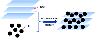
The morphology and microstructure of LiFePO4 cathodes with 1 wt% different sizes of GN and 9 wt% SP (Fig. 1b–d), and with 10 wt% SP for the reference (Fig. 1a), were characterized by scanning electron microscopy (SEM) at a high magnification, as shown in Fig. 1. We could be told from these figures that LiFePO4 active materials refer to secondary quasi-spherical microparticles with diameters of 400–600 nm in agreement with the product test report provided by producers. It is clear that the GN are closely packed in the perpendicular direction to active materials and disperse well among LiFePO4 particles. Simultaneously, a random aggregation of graphene sheets can also be observed, suggesting that most of LiFePO4 particles are surrounded by soft graphene sheets, which is ascribed to that SP as nanoscale particles can effectively decrease the agglomeration of GN. As shown in Fig. 2, nanoscale particles could be adsorbed onto the surface of the GN and hold it there, and prevent agglomeration of GN from occurring, resulting in highly taking full advantage of electrochemical utilization of GN.20 Therefore, these closely packed flakes could establish an effective electronic conducting network, as clearly illustrated by many researchers.4,16,21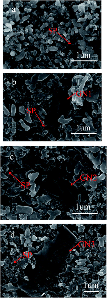 | ||
| Fig. 1 SEM images of LFP with (a) 10% SP (×50.0k); (b) 9% SP and 1% GN1 (×50.0k); (c) 9% SP and 1% GN2 (×50.0k); (d) 9% SP and 1% GN3 (×28.0k). | ||
We have investigated the effects of various GN fractions on the discharge plateau performance and specific capacity of LFP/GN to optimize the component of different conductive additives. As shown in Fig. 3, apparent and great enhancement of the charge/discharge profile are found for the three LFP/GN system at 0.1C rate, as compared to the cases of the LiFePO4 with only SP. We can also find a very sound difference between the three cases with different sizes of GN (Fig. 3d), which fell out as we had anticipated. It can be drawn from Fig. 3a and b that the performance of the LFP/GN1 and LFP/GN2 electrodes become better with the increase of the GN fraction from 0.5 to 1.0 wt%, and with the specific capacity of LFP with 1.0 wt% GN1 and LFP with 1.0 wt% GN2 mostly maintained about 165 mA h g−1 and 163 mA h g−1 respectively. The LFP with 10 wt% SP for the reference had lower specific capacity with about 155 mA h g−1. This is mainly up to the 0.5 wt% GN1 and GN2 fraction are too low in the cathode materials to take full advantage of the “plane-to-point” mode of GN-based additives, which is more advantage than the “point-to-point” mode of SP-based additives to establish an effective conducting network. While, the opposite result occurred when a further increase is employed from 1.0 to 3.0 wt%, owing to GN would more tend to agglomerate together into thickly aggregated structures and be difficult to disperse well in the active materials,3 which greatly increase the probability of hindrance of lithium ion transport and result in a heavy polarization. However, the specific capacity of LFP with 1.0 wt% GN3 was about 161 mA h g−1, slightly worse than that of LFP with 0.5 wt% GN3 (162.5 mA h g−1). Even, when GN3 fractions increased to 3%, the capacity was 148 mA h g−1. Which is considered to prolong more times of the distance for lithium ion diffusion than that with GN1 and GN2, leading to more heavy polarization and longer distance for lithium ion diffusion with more GN3 fractions. The results once again proved that the large-size GN is much easier to hinder lithium ion transport for nanometer grade cathode materials. Based on this point of view, small-size GN may be more suitable for nanometer grade cathode materials. Generally, the LFP electrode with 1.0 wt% GN1, 1.0 wt% GN2 and 0.5 wt% GN3 show the better charge/discharge performance among their respective tested cases. From the preliminary results, we can arrive at a preliminary conclusion that the optimal content of GN varies according to the size of GN, that LFP with small-size GN shows better electrochemical performance than that with large-size GN at 0.1C rate under this experimental condition. Which on account that the large-size GN would more tend to prolong the lithium ion transport path and increase polarization in the active materials.
Further studies on the relationship between electrochemical properties of LiFePO4 and different size GN were done in this paper. We have investigated the effect of the same content of LFP/GN with different sizes of GN on the rate performance comprehensively. Fig. 4 presented the rate performances of the LFP/GN with different sizes of GN, LiFePO4 with 10 wt% SP for the reference. It can be seen that the rate performance of the LFP/GN electrode becomes worse with the increase of GN sizes. Regarding each specific capacity at 0.1C as 100%, the rate performance of the electrode with those three different sizes of graphene improve significantly and have comparable capacity at 0.1–1.0C rate. However, a sudden capacity loss at 2C, 5C discharge rate appeared for LFP/GN3, while that obvious loss at high discharge rate did not appear for LFP/GN1 and LFP/GN2 case, and the specific capacity at 5C of LFP/GN1 and LFP/GN2 electrode are 112 mA h g−1 and 104 mA h g−1, and capacity retention of 5C compared to 0.1C are 67.9% and 63.8%, superior to LFP/GN3 79 mA h g−1 and LFP/SP 85 mA h g−1 (48.5% and 54.8%, respectively). The results suggest that the rate performance of the electrode become worse with the increase of the GN size. This may be due to the different electrode structure shown in Fig. 5, which represents possible conducting modes in LiFePO4 cathode based on the SEM images. From the mechanism map we can deduce that the poor rate performance of the LFP/GN3 is caused by poor lithium ion transport. It is easily understood that, with the increase of GN size, the length of ion transport path is prolonged more and the ionic conductivity decreases more greatly, which can be attributed to the fact that lithium ion transport path is more efficient in SP case than in GN case since the size of SP is much smaller than GN.3,16,21 In a complete charge/discharge process, electrons and lithium ion must reach the same electrode material simultaneously. From this view point, two factors should be considered for structuring an optimal conducting network. One is the conductivity, with the increase of the GN fractions, the electronic conductivity of the poorly conductive LiFePO4 improved greatly, which is due to that GN is a one-atom-thick allotrope of carbon, π-electrons are “free” and move more easily, which have great advantages in electronic conductivity over other conductive carbons.22 On the other hand, the “plane-to-point” mode of GN-based additives could bridge the active materials as effectively as possible, and more efficient than the “point-to-point” mode of conventional carbon additives where high fractions and intimately contacted particles are needed to form an effective electron network. Another important factor can be the lithium ion diffusion. As shown in Fig. 6, lithium ion diffusion through basal plane of GN is rather limited. Lithium diffusion may only occur through some defect sites and grain boundaries,19 which would block the most efficient and shortest paths for the lithium ion transport and become worse with the increase of the GN size. Therefore, the large-size GN are more likely to prolong the lithium ion diffusion path and amplify the “barrier effect” of GN, which were proved out from the above results (as Fig. 3 shown).
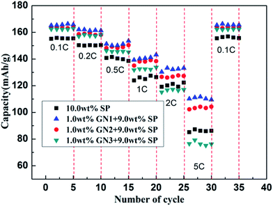 | ||
| Fig. 4 Comparison of rate performance of LFP with different sizes of GN at different discharge rates. | ||
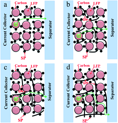 | ||
| Fig. 5 The mechanism map of lithium ion transport paths in different systems utilizing GN with different sizes and SP as conductive additives. | ||
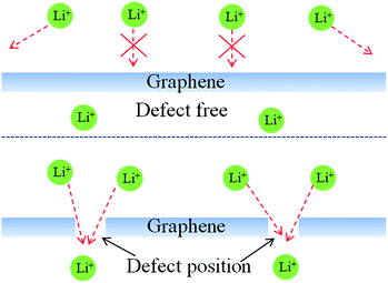 | ||
| Fig. 6 Schematics of lithium ion diffusion mechanism on the surface of graphene with different defect population. | ||
We measured cyclic voltammograms to shed light on the polarization effect of various LFP samples, Fig. 7a show the cyclic voltammograms of the LFP/GN and LFP/SP electrodes (scan rate is 0.1 mV s−1) under ambient temperature. More symmetric and poignant shape of redox peaks of LFP/GN than the LFP/SP cases suggest a higher electrochemical reactivity and lower ohmic resistance of LFP/GN than that of LFP/SP, which is due to the “plane-to-point” mode of GN-based additives bridge active LiFePO4 particles in a more effective and efficient way than the “point-to-point” mode of SP cases. Moreover, bigger interval between the oxidation and reduction peak was observed with the increase of GN sizes, which denoted increasing of polarization with the increase of GN sizes. This may be due to GN is barrier for lithium ion transport to cut off the most efficient transmission path,9,10 the more bigger GN sizes, the longer the length of ion transport path. Which is consistent with the results of our experiment.
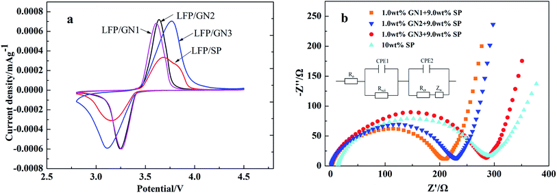 | ||
| Fig. 7 Cyclic voltammograms (a) and EIS spectra (b) of LFP with different sizes GN and LFP/SP as a reference. | ||
To deeply understand the remarkably enhancement of performance of LFP/GN with different sizes of GN, compared with the original materials without GN respectively, EIS measurement was also employed, the EIS data is simulated through the equivalent circuit in Fig. 7b. The EIS profiles consist of a partially quasi-semicircle at the range from high to middle frequency and a sloping line in the low frequency region. The intercept of the real axis at the high frequency range can be attributed to the ohmic resistance (RO), which refers to the sum of resistance of the electrodes, electrolyte and separator. The semicircle at the high and middle frequency range stands for the charge transfer resistance (Rct). The slope line at low frequency range represents the Warburg impedance, which is attributed to lithium ion diffusion in the electrode.23,24 As shown in Fig. 7b from the intersection of the real axis, it can be drawn that the bulk ohmic resistance (RO) of the LiFePO4 with three different sizes of graphene approximate very much, and much lower than that of the LiFePO4 with 10% SP. Therefore, the significant difference in the bulk ohmic resistance (RO) suggests the superiority of the electronic conductivity of GN over SP as the conductive additive. Graphene nanosheet (GN), together with Super-P (SP) could build a more effective electron transport network in lithium ion batteries. The semicircle of electrode LFP/SP was found to be larger than that of electrode LFP/GN1, LFP/GN2, and slightly smaller than electrode LFP/GN3 from the Nyquist plots. The EIS results are consistent with our above electrochemical measurements, and further confirming that the graphene with different sizes could affect electrochemical performance of LiFePO4. That is, LFP/GN with small size GN1 and GN2 show much better interface contact efficiency due to the more efficient “plane-to-point” mode to “bridge” active LiFePO4 particles sufficiently, resulting in better charge transfer and satisfied electronic conductivity which promotes the electrochemical reaction.3,10 The Rct values increase with the increase of GN sizes, which have been proved above. This is because with the increase of the GN sizes, GN tends to prolong the length of ion transport path and hinder dispersion between the electrolytes and active materials, leading to the ionic conductivity decreases substantially.
4. Conclusions
From the above discussion, some suggestive conclusions can be arrived at based on our experimental results. An effective electronic conducting network could be constructed and significantly improved the electrochemical performance of LiFePO4 by GNs and SP as conductive additives simultaneously, as compared to the conventional conducting ones. With the increase of GN sizes, the specific capacity and rate performance tend to get worse for nanometer grade LiFePO4, due to the length of ion transport path is prolonged and the ionic conductivity decreases greatly by “barrier effect” of GN. Small-size GN could keep a effective balance between fast lithium ion diffusion and increased electron transport for nanometer grade LiFePO4. Therefore, small-size GN may be more suitable for nanometer grade LiFePO4 cathode materials. These efforts will accelerate a final commercial application of GN additive and go one step further in LIB real applications.Acknowledgements
This work was financially supported by the Government of Japan for the Monbusho Fellowship, National Natural Science Foundation of China (Y6062219BM), Qingdao Industrial Energy Storage Technology Institute.Notes and references
- P. R. Ilango, R. Gnanamuthu, Y. N. Jo and C. W. Lee, J. Ind. Eng. Chem., 2016, 36, 121–124 CrossRef CAS.
- X. Zhou, F. Wang, Y. Zhu and Z. Liu, J. Mater. Chem., 2011, 21, 3353 RSC.
- F.-Y. Su, C. You, Y.-B. He, W. Lv, W. Cui, F. Jin, B. Li, Q.-H. Yang and F. Kang, J. Mater. Chem., 2010, 20, 9644 RSC.
- C. Gong, Z. Xue, S. Wen, Y. Ye and X. Xie, J. Power Sources, 2016, 318, 93–112 CrossRef CAS.
- J. Wang and X. Sun, Energy Environ. Sci., 2015, 8, 1110–1138 CAS.
- S. Yang, D. Wang, G. Liang, Y. M. Yiu, J. Wang, L. Liu, X. Sun and T.-K. Sham, Energy Environ. Sci., 2012, 5, 7007 CAS.
- S. Kim, V. Mathew, J. Kang, J. Gim, J. Song, J. Jo and J. Kim, Ceram. Int., 2016, 42, 7230–7236 CrossRef CAS.
- X. Meng, B. Han, Y. Wang and J. Nan, Ceram. Int., 2016, 42, 2599–2604 CrossRef CAS.
- H. Yuan, X. Wang, Q. Wu, H. Shu and X. Yang, J. Alloys Compd., 2016, 675, 187–194 CrossRef CAS.
- J. Yang, J. Wang, Y. Tang, D. Wang, X. Li, Y. Hu, R. Li, G. Liang, T.-K. Sham and X. Sun, Energy Environ. Sci., 2013, 6, 1521 CAS.
- N. Zhao, Y. Li, X. Zhao, X. Zhi and G. Liang, J. Alloys Compd., 2016, 683, 123–132 CrossRef CAS.
- Z. Li, Z. Peng, H. Zhang, T. Hu, M. Hu, K. Zhu and X. Wang, Nano Lett., 2016, 16, 795–799 CrossRef CAS PubMed.
- Y. Zhao, L. Peng, B. Liu and G. Yu, Nano Lett., 2014, 14, 2849–2853 CrossRef CAS PubMed.
- H. Guo, X. Song, Z. Zhuo, J. Hu, T. Liu, Y. Duan, J. Zheng, Z. Chen, W. Yang, K. Amine and F. Pan, Nano Lett., 2016, 16, 601–608 CrossRef CAS PubMed.
- B. Zhang, Y. Yu, Y. Liu, Z. D. Huang, Y. B. He and J. K. Kim, Nanoscale, 2013, 5, 2100–2106 RSC.
- R. Tang, Q. Yun, W. Lv, Y.-B. He, C. You, F. Su, L. Ke, B. Li, F. Kang and Q.-H. Yang, Carbon, 2016, 103, 356–362 CrossRef CAS.
- Y.-F. Tang, F. Huang, H. Bi, Z. Liu and D. Wan, J. Power Sources, 2012, 203, 130–134 CrossRef CAS.
- W. Wei, W. Lv, M.-B. Wu, F.-Y. Su, Y.-B. He, B. Li, F. Kang and Q.-H. Yang, Carbon, 2013, 57, 530–533 CrossRef CAS.
- F. Yao, F. Gunes, H. Q. Ta, S. M. Lee, S. J. Chae, K. Y. Sheem, C. S. Cojocaru, S. S. Xie and Y. H. Lee, J. Am. Chem. Soc., 2012, 134, 8646–8654 CrossRef CAS PubMed.
- J. Yan, T. Wei, B. Shao, F. Ma, Z. Fan, M. Zhang, C. Zheng, Y. Shang, W. Qian and F. Wei, Carbon, 2010, 48, 1731–1737 CrossRef CAS.
- F.-Y. Su, Y.-B. He, B. Li, X.-C. Chen, C.-H. You, W. Wei, W. Lv, Q.-H. Yang and F. Kang, Nano Energy, 2012, 1, 429–439 CrossRef CAS.
- A. H. Castro Neto, F. Guinea, N. M. R. Peres, K. S. Novoselov and A. K. Geim, Rev. Mod. Phys., 2009, 81, 109–162 CrossRef CAS.
- Y. Shi, S.-L. Chou, J.-Z. Wang, D. Wexler, H.-J. Li, H.-K. Liu and Y. Wu, J. Mater. Chem., 2012, 22, 16465 RSC.
- V. Freger, Electrochem. Commun., 2005, 7, 957–961 CrossRef CAS.
| This journal is © The Royal Society of Chemistry 2017 |

