 Open Access Article
A high performance ZnO based photoelectrochemical cell type UV photodetector with [Co(bpy)3]3+/2+ electrolyte and PEDOT/ITO counter electrode
Jieni Li ,
Xingming Wu,
Mandar M. Shirolkar,
Ming Li,
Chunye Xu
 and
Haiqian Wang*
Hefei National Laboratory for Physical Sciences at the Microscale, University of Science and Technology of China, Hefei, Anhui 230026, People's Republic of China. E-mail: hqwang@ustc.edu.cn
First published on 30th March 2017
Abstract
We fabricated a high performance self-powered photoelectrochemical cell (PECC) type UV photodetector with ZnO nanorod arrays (NRs) as the photoanode, [Co(bpy)3]3+/2+ as the electrolyte and ITO glass coated by polymer poly(3,4-ethylenedioxythiophene) (PEDOT), PEDOT/ITO, as the counter electrode (CE). The UV photodetector shows a good photovoltaic performance (VOC = 0.5 V, ISC = 6.2 μA) and a high photosensitivity of 263 under the illumination of 365 nm UV light with an intensity of 2 mW cm−2. The device also shows a high response speed (response time < 0.2 s). The high photosensitivity and rapid response speed are attributed to the good electrocatalytic activity of PEDOT towards Co-complex redox shuttle. The high performance of the detector, together with the Pt-free low cost CE and the facile fabricating method, makes the device promising in optoelectronic applications.
1. Introduction
Self-powered UV photodetectors have lots of promising applications, including communications, astronomy, environmental monitoring, chemical analysis, spectrometer and medical instrument, etc.1–4 So far, large numbers of self-powered UV photodetectors with different structures have been fabricated, including Schottky junctions,5,6 p–n junctions7,8 and PECC structures.9 Most of the reported self-powered UV photodetectors based on p–n junctions or Schottky junctions are composed of single nanostructures or high quality epitaxial films; the complex fabrication process and the dependence of the high purity materials make the cost of the device high. The current output of a single nanostructure device is usually weak, which requires a high-precision and expensive detecting circuit. Compared to the p–n junction or Schottky junction, the PECC structure has the advantages of cost effective, simple fabrication method and environment friendly raw materials.10 Moreover, a PECC structure can be fabricated with large active area and thus strong current output signal, which makes it suitable for low intensity UV light environments.A typical PECC type photodetector is made up of three important parts, including a wide gap semiconductor photoanode, an electrolyte and a CE.11 When the semiconductor photoanode is illuminated by UV light, photo excited electrons transfer to the conduction band (CB) of the photoanode and then enter the external circuit, leaving holes in the valence band (VB). These holes oxidize the redox couple at the reduced state to its oxidized state at the interface between the semiconductor and electrolyte. The redox couple at the oxidized states diffuse to the interface of the electrolyte and CE and combine with the electrons from external circuit.12,13
Currently, TiO2 and ZnO are the most frequently used photoanode materials for the PECC type UV photodetectors.14–16 The band structure of ZnO is similar to that of TiO2, but ZnO has a higher electron mobility compared with TiO2.17 What's more, ZnO can be prepared in various morphologies, such as nanorods, nanoneedles and nanobelts, by simple and cost-effective techniques.18,19 Among them, one-dimensional ZnO nanorods provide a direct pass-way for electrons, and are a promising material as the photoanode in PECC type UV photodetectors due to its good crystal quality, high aspect ratio and excellent carrier transport properties.20 In addition, ZnO has a high UV light selectivity as compared with TiO2, because the absorption edge of ZnO is approximately 380 nm and sharp, but that of TiO2 is approximately 400 nm and often extends slightly to the visible region.21,22
The electrolyte provides ionic conductivity and transfers carriers between the semiconductor and CE in a PECC type UV photodetector.23 So far, I−/I3− redox couple electrolyte is frequently used in PECC type UV photodetectors. However, the I−/I3− redox couple electrolyte is not good for long-term operation due to its high corrosivity and instability, which means that some common metallic catalysts and sealing materials can't be used in the I−/I3− electrolyte system.24 Although, H2O and Na2SO4 are green and safe aqueous electrolytes, the performances of UV photodetectors based on these electrolytes are relatively poor.25,26 In recent reports about dye sensitized solar cells (DSSCs), the [Co(bpy)3]3+/2+ redox system is investigated to be an alternative redox couple.27–29 The [Co(bpy)3]3+/2+ redox system has higher redox potential (0.56 V) than that of the I−/I3− system (0.35 V) and reduced corrosiveness towards metallic components.30 However, the sluggish electron transfer between Co(II) and Co(III) complex results in a slow regeneration process of [Co(bpy)3]2+ at CE.31,32 Therefore, CE with high catalytic performance for the regeneration of [Co(bpy)3]2+ is desired.33 Currently, Pt-coated transparent conductive oxide (TCO) glass is the most frequently used CE. Pt is demonstrated to be an outstanding CE catalyst owing to its good catalytic performance and stability.34 However, Pt is very expensive and its reserves are limited. In DSSCs, varieties of Pt-free CE catalysts are explored, including carbon materials, conductive polymers and inorganic materials. Among them, PEDOT is a promising candidate for replacing Pt as CE catalyst due to its high electrochemical stability and catalytic performance towards [Co(bpy)3]3+/2+ redox system.35,36
In the present work, we report a PECC type UV photodetector with ZnO NRs photoanode and the [Co(bpy)3]2+/3+ electrolyte. It is demonstrated that the PEDOT/ITO CE has a good catalytic performance towards the regeneration of [Co(bpy)3]2+. The ZnO NRs based photodetector with PEDOT/ITO CE and [Co(bpy)3]2+/3+ electrolyte displays a high photosensitivity and fast response speed at zero bias.
2. Experimental
2.1 Synthesis of ZnO NRs and the Co-complex
All source chemicals were of analytical grade and used directly without any post treatment. ZnO NRs were grown on glass substrate coated with an Al doped ZnO (AZO) seed layer. Glass substrates were ultrasonic cleaned with acetone, ethanol and deionized water, successively. A 400 nm AZO seed layer was initially deposited by magnetron sputtering method. The sputtering machine has two Al2O3 doped ZnO ceramic targets (2.2 wt%, Al2O3, purity ≈ 99.9%).37 The sputtering power was 6000 W and Ar was imported as working gas, the flow rate of which was 200 sccm. Then ZnO NRs were fabricated using a simple hydrothermal method.38 The glass substrates with 400 nm AZO seed layer were suspending in a 0.02 M equimolar solution of zinc acetate (Zn(Ac)2) and hexamethylene-tetramine (HMT) with the seed layer facing the bottom of the Teflon liner of the stainless-steel vessel. The reactors were kept at 90 °C in an oven for 12 h. After the reactions were finished, the products were rinsed three times using distilled water and ethanol. Then the products were dried at 60 °C for 2 h. Finally, the as-grown ZnO NRs are white in color.The cobalt complex [Co(bpy)3](PF6)2 is synthesized following the reported procedures.39–41 A mixture of CoCl2·6H2O and 2,2′-bipyridyl (molar ratio of 1![[thin space (1/6-em)]](https://www.rsc.org/images/entities/char_2009.gif) :
:![[thin space (1/6-em)]](https://www.rsc.org/images/entities/char_2009.gif) 3) were dissolved in methanol and refluxed for 2 h. An excessive amount of ammonium hexafluorophosphate was added to the resulting solution at room temperature. The products were filtrated and the residue was dried in a vacuum oven. We obtained a yellow solid of [Co(bpy)3](PF6)2. The oxidation of [Co(bpy)3](PF6)2 was carried out at room temperature using NOBF4 in acetonitrile. After the reaction was finished, the solvent was removed under low pressure condition, then acetonitrile was used as solvent to dissolve the residue again. An excessive amount of NH4PF6 was added to the solution to make [Co(bpy)3](PF6)3 precipitate, which was then filtrated and dried in a vacuum oven. The final products were used directly without further treatments.
3) were dissolved in methanol and refluxed for 2 h. An excessive amount of ammonium hexafluorophosphate was added to the resulting solution at room temperature. The products were filtrated and the residue was dried in a vacuum oven. We obtained a yellow solid of [Co(bpy)3](PF6)2. The oxidation of [Co(bpy)3](PF6)2 was carried out at room temperature using NOBF4 in acetonitrile. After the reaction was finished, the solvent was removed under low pressure condition, then acetonitrile was used as solvent to dissolve the residue again. An excessive amount of NH4PF6 was added to the solution to make [Co(bpy)3](PF6)3 precipitate, which was then filtrated and dried in a vacuum oven. The final products were used directly without further treatments.
2.2 Preparation of the CEs and cyclic voltammogram measurement
The Pt/ITO CEs were fabricated by spin coating 10 mM H2PtCl6 isopropanol solution on ITO glass (185 nm in ITO thickness, >84% transmittance, 7 Ω cm) and then annealed in a 350 °C oven for 30 minutes. The PEDOT/ITO CEs were prepared by drop coating PEDOT solution (Sigma) on the ITO glass and then dried at 60 °C. Cyclic voltammograms of the Pt/ITO, PEDOT/ITO and ITO CEs were measured using an electrochemical workstation (IM6eX, Zahner) with a three electrode configuration. The CE and reference electrode were Pt film and silver wire, respectively. 2 mM [Co(bpy)3](PF6)2 and 0.1 M LiClO4 acetonitrile solution was used as the electrolyte. The voltage swept from −0.4 to +0.8 V with a sweep speed of 50 mV s−1. A Teflon container was employed to fix and support the electrodes. For each sample, the surface areas immersed in the electrolyte are the same. Also, the distances of the three electrodes are the same in all the experiments.2.3 Assembly of the PECC-type UV photodetector
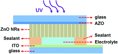
The PECC-type UV photodetector was assembled in a sandwich structure, similar as a DSSC. We initially assembled the ZnO NRs photoanode and the CEs with a space between them. The electrolyte solution is composed of 0.2 M [Co(bpy)3](PF6)2, 0.02 M [Co(bpy)3](PF6)3 and 0.1 M LiClO4 in acetonitrile. The electrolyte is introduced into the space between ZnO NRs and CE. Finally, the UV photodetector is sealed. The ZnO NRs based PECC-type UV photodetectors has a photo active area of 0.12 cm2. The schematic device structure of the photodetector is shown in Fig. 1.The crystal structure of the ZnO NRs was characterized by X-ray diffraction (XRD) with Cu-Kα radiation. The surface morphology of the ZnO NRs are characterized by a scanning electron microscope (SEM, JSM-6700F). The Raman spectrum was conducted at room temperature using an excitation wavelength of 514.5 nm. The absorption spectroscopy was measured by UV-Vis-IR4100 spectrophotometer (Hitachi Co). The photoluminescence (PL) spectra were measured at room temperature using a PL spectroscopy (FLUOROLOG-3-TAU) with a 325 nm wavelength excitation source. The voltage–current (V–I) curves of the UV detectors were recorded with Keithley 2420C sourcemeter. The time response photocurrent was recorded using an electrochemical workstation (IM6eX, Zahner). The UV light source (WFH-203) used for the photo response measurements was a low pressure mercury-vapor fluorescent lamp with the 365 nm emission peak as the main emission in the spectrum. A visible light cut-off filter is used to eliminate the visible light. The optical power density of the UV light is 2.0 mW cm−2 measured by a Thorlabs optical power meter PM100A.
3. Results and discussion
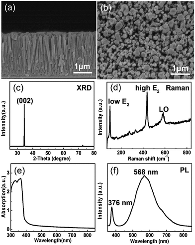
The cross-sectional and surface morphologies of the ZnO NRs are displayed in Fig. 2(a) and (b). The ZnO NRs are growing vertically on 400 nm thick AZO coated glass substrate. The diameter range of the ZnO nanorods is 100–300 nm. The ZnO NRs film shows a thickness of 2 μm and a density of 1.8 × 109 cm−2. The loosely packed ZnO NRs favor the contact between the ZnO NRs and liquid electrolyte. Fig. 2(c) shows the XRD pattern of the ZnO NRs on the AZO coated glass substrate. The sharp (002) peak at 34.5° indicates that ZnO NRs have wurtzite structure. The absence of other diffraction peaks indicates that the sample grows along c-axis preferred orientation and perpendicularly to the glass substrate. The Raman spectrum of the ZnO sample is displayed in Fig. 2(d). The strong low frequency E2 (100 cm−1) and high frequency E2 (438 cm−1) peaks suggest that the ZnO NRs are well crystallized hexagonal wurtzite structure, which is also observed in other reports.42 The weak peak of LO mode centered at 576 cm−1 may be related to oxygen vacancy.38 Fig. 2(e) displays the UV-Vis absorption spectra of the ZnO NRs. The characteristic band edge absorbance appears at 380 nm, which means that the ZnO NRs can absorb the UV light with wavelength below 380 nm. Fig. 2(f) shows the PL spectrum of the ZnO NRs. The 376 nm UV emission peak is attributed to the near band–edge transition and the strong visible emission peak at about 570 nm is associated with oxygen vacancy. It is reported that the oxygen vacancy related defects make the photo generated electron–hole pairs separating effectively and increase the photocurrent.43,44 Thus, the synthesized wurtzite ZnO NRs are appropriate for the photoanode of the PECC type UV photodetector.Apart from the photoanode, the electrolyte and CE also play vital roles in the performance of the PECC type UV photodetector. The structure of a PECC type UV photodetector is similar to DSSCs,45 except that the photoanode is not covered by dye molecules Fig. 3(a). In the present study, we use [Co(bpy)3]3+/2+ as the electrolyte. When a UV light is illuminating on the device, [Co(bpy)3]2+ in the electrolyte is oxidized by the holes generated in the VB of ZnO NRs and transforms to [Co(bpy)3]3+. [Co(bpy)3]3+ then transfers through the electrolyte to CE and is reduced by the electrons there. However, the electron transfer to [Co(bpy)3]3+ is sluggish due to the large activation barrier for spin changes from Co(III) to Co(II) and the electronic blocking effect of the tridentate ligands.31,32 A slow electron transfer rate is preferred at the photoanode side because it slows down the recombination of [Co(bpy)3]3+ with the electrons at CE. Unfortunately, the sluggish electron transfer also results in a slow regeneration of [Co(bpy)3]2+ at the CE side, which reduces the photocurrent of the PECC type photodetector.
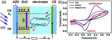 | ||
| Fig. 3 (a) Energy diagram of the PECC-type UV photodetector. (b) Cyclic voltammograms of the ITO, Pt/ITO and PEDOT/ITO CEs in the [Co(bpy)3]2+/3+ electrolyte. | ||
The regeneration of [Co(bpy)3]2+ at the CE surface is an electrochemical process, and the kinetics of the regeneration can be effectively promoted by a proper selection of CE with high catalytic performance. Fig. 3(b) compares the catalytic performance of ITO, Pt/ITO and PEDOT/ITO CEs over [Co(bpy)3]2+/3+ complex according to the cyclic voltammetry measurements. Typical oxidation and reduction peaks are clearly observed for all the CEs. The values of peak separation (Epp) for ITO, Pt/ITO and PEDOT/ITO CEs are 0.68, 0.56 and 0.33 V, respectively. The smaller the peak separation, the higher the electrocatalytic activities towards the redox shuttle.46 The results in Fig. 4(b) indicate that Pt/ITO has a better catalytic activity than ITO. Currently, Pt is the most frequently used CE catalyst because of its good catalytic property. It is interesting to note that the Pt-free PEDOT/ITO CE shows the smallest Epp of 0.33 V and hence the highest catalytic performance. Park et al.36 reported that the charge-transfer resistance of PEDOT:Tos/glass CE is 5 to 10 times lower than the Pt/FTO CE for [Co(bpy)3]3+/2+ complex in DSSCs, indicating the catalytic activity of PEDOT is superior to Pt.
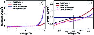 | ||
| Fig. 4 (a) V–I curves of the Pt/ITO and PEDOT/ITO CE photodetectors illuminated by 365 nm UV light of 2 mW cm2. (b) A magnified view of V–I curves of the two devices near zero bias. | ||
The opto-electronic characterization of the PECC-type UV photodetector was performed by using 365 nm UV light with an intensity of 2 mW cm−2. The V–I plots of the photodetectors with Pt/ITO and PEDOT/ITO CEs under dark and UV light are compared in Fig. 4(a). The dark V–I curves of the devices both show a well-defined rectifying behavior. The V–I curves near zero bias are magnified in Fig. 4(b). The photodetectors exhibit clearly photovoltaic effect, indicating that the devices can be operated at a self-powered mode. The open circuit voltages (VOC) of the photodetectors with Pt/ITO CE and PEDOT/ITO CE are 0.2 and 0.5 V, respectively. The short circuit currents (ISC) are 2.7 and 6.2 μA, respectively. By using the PEDOT/ITO CE, both the VOC and ISC are improved obviously. In principle, the VOC of a PECC type UV photodetectors is related to the difference of the Fermi level (EF) of the photoanode and the redox level of the electrolyte. In the present case, the two devices have the same photoanode and electrolyte, so the different VOC values are more likely determined by the differences in recombination rates of [Co(bpy)3]3+ with electrons at CE. According to the result of cyclic voltammetry, the PEDOT/ITO CE shows higher electrocatalytic performance towards the regeneration of [Co(bpy)3]2+, which reduces the concentration of [Co(bpy)3]3+ in the electrolyte. Thus the recombination rate at the photoanode side decreases and the VOC loss reduces.
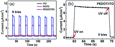
Fig. 5(a) displays the I–t curves of the self-powered UV photodetectors with ITO, Pt/ITO and PEDOT/ITO CEs at zero bias. The incident UV light is switched on for 10 s and off for 20 s. Seven repeated cycles are recorded. It is clearly seen that the photocurrents are stable and repeatable. It can be clearly seen that the device with PEDOT/ITO CE has a highest photocurrent of 7.91 μA cm−2, which is much higher than the 4.3 μA cm−2 of the Pt/ITO CE device and the 0.25 μA cm−2 of the ITO CE device. The response time is an important parameter for photodetectors. The rise time (τr) is defined as the time rising to 90% of the photocurrent and the decay time (τd) is the time falling to 10% of the photocurrent.47 Fig. 5(b) magnified one on/off circle in the I–t plots of the device with PEDOT/ITO CE. The rise time and the decay time are both less than 0.2 s, demonstrating a rapid response speed. Considering the time resolution (0.2 s) of our instrument, the response time should be even smaller. Thereby, the device with PEDOT/ITO CE shows a high photoresponse performance.
The photosensitivity is another important parameter for photodetectors and can be expressed as (Iph − Idark)/Idark, where Iph represents the photocurrent and Idark represents the dark current. All the parameters of the three photodetectors are calculated and shown in Table 1. The device with PEDOT/ITO CE shows a highest photosensitivity of 263, which is considerably higher than the values of the devices with Pt/ITO CE (17) and ITO CE (2.3). The parameters of ZnO based PECC type UV photodetectors reported in other literatures16,25,26 are also collected in Table 1. It is seen that our device with PEDOT/ITO CE displays the highest photosensitivity, while the other parameters such as Iph, (τr) and (τd) are comparable.
4. Conclusions
In summary, we fabricated a high performance ZnO based self-powered PECC-type UV photodetector with a facile method. It is demonstrated that the combination of [Co(bpy)3]2+/3+ complex with PEDOT/ITO CE ensures a high VOC and fast regeneration of [Co(bpy)3]2+ at the CE. The UV photodetector with PEDOT/ITO CE exhibits a high photosensitivity of 263 and a rapid response speed (response time < 0.2 s) at zero bias. The high performance of the detector, together with the Pt-free PEDOT/ITO CE and the facile fabrication method, makes the device promising in optoelectronic applications.Acknowledgements
This work is supported by the National Natural Science Foundation of China (Grant No. 21427804).References
- L. Sang, M. Liao and M. Sumiya, Sensors, 2013, 13, 10482–10518 CrossRef CAS PubMed.
- S. M. Hatch, J. Briscoe and S. Dunn, Adv. Mater., 2013, 25, 867–871 CrossRef CAS PubMed.
- J. Lu, C. Xu, J. Dai, J. Li, Y. Wang, Y. Lin and P. Li, Nanoscale, 2015, 7, 3396–3403 RSC.
- W. Tian, C. Zhang, T. Zhai, S. L. Li, X. Wang, J. Liu, X. Jie, D. Liu, M. Liao, Y. Koide, D. Golberg and Y. Bando, Adv. Mater., 2014, 26, 3088–3093 CrossRef CAS PubMed.
- R. Y. Gunji, M. Nakano, A. Tsukazaki, A. Ohtomo, T. Fukumura and M. Kawasaki, Appl. Phys. Lett., 2008, 93, 3 CrossRef.
- M. Nakano, T. Makino, A. Tsukazaki, K. Ueno, A. Ohtomo, T. Fukumura, H. Yuji, S. Akasaka, K. Tamura, K. Nakahara, T. Tanabe, A. Kamisawa and M. Kawasaki, Appl. Phys. Lett., 2008, 93, 123309 CrossRef.
- Y. Q. Bie, Z. M. Liao, H. Z. Zhang, G. R. Li, Y. Ye, Y. B. Zhou, J. Xu, Z. X. Qin, L. Dai and D. P. Yu, Adv. Mater., 2011, 23, 649–653 CrossRef CAS PubMed.
- S. M. Hatch, J. Briscoe, A. Sapelkin, W. P. Gillin, J. B. Gilchrist, M. P. Ryan, S. Heutz and S. Dunn, J. Appl. Phys., 2013, 113, 204501 CrossRef.
- X. Li, C. Gao, H. Duan, B. Lu, X. Pan and E. Xie, Nano Energy, 2012, 1, 640–645 CrossRef CAS.
- Y. Xie, L. Wei, Q. Li, Y. Chen, S. Yan, J. Jiao, G. Liu and L. Mei, Nanotechnology, 2014, 25, 075202 CrossRef PubMed.
- L. Chen, X. Li, Y. Wang, C. Gao, H. Zhang, B. Zhao, F. Teng, J. Zhou, Z. Zhang, X. Pan and E. Xie, J. Power Sources, 2014, 272, 886–894 CrossRef CAS.
- C. Gao, X. Li, B. Lu, L. Chen, Y. Wang, F. Teng, J. Wang, Z. Zhang, X. Pan and E. Xie, Nanoscale, 2012, 4, 3475–3481 RSC.
- L. M. Gonçalves, V. de Zea Bermudez, H. A. Ribeiro and A. M. Mendes, Energy Environ. Sci., 2008, 1, 655 Search PubMed.
- W.-J. Lee and M.-H. Hon, Appl. Phys. Lett., 2011, 99, 251102 CrossRef.
- C. Gao, X. Li, X. Zhu, L. Chen, Y. Wang, F. Teng, Z. Zhang, H. Duan and E. Xie, J. Alloys Compd., 2014, 616, 510–515 CrossRef CAS.
- Y. Zeng, X. Pan, W. Dai, Y. Chen and Z. Ye, RSC Adv., 2015, 5, 66738–66741 RSC.
- Z. H. Chen, Y. B. Tang, C. P. Liu, Y. H. Leung, G. D. Yuan, L. M. Chen, Y. Q. Wang, I. Bello, J. A. Zapien, W. J. Zhang, C. S. Lee and S. T. Lee, J. Phys. Chem. C, 2009, 113, 5 Search PubMed.
- L. Guo, H. Zhang, D. Zhao, B. Li, Z. Zhang, M. Jiang and D. Shen, Sens. Actuators, B, 2012, 166–167, 12–16 CrossRef CAS.
- C. S. Lao, M.-C. Park, Q. Kuang, Y. Deng, A. K. Sood, D. L. Polla and Z. L. Wang, J. Am. Chem. Soc., 2007, 129, 2 CrossRef PubMed.
- T. Zhai, X. Fang, M. Liao, X. Xu, H. Zeng, B. Yoshio and D. Golberg, Sensors, 2009, 9, 6504–6529 CrossRef CAS PubMed.
- D. Zhang, G. Li, F. Wang and J. C. Yu, CrystEngComm, 2010, 12, 1759 RSC.
- L. Wang, D. Zhao, Z. Su, F. Fang, B. Li, Z. Zhang, D. Shen and X. Wang, Org. Electron., 2010, 11, 1318–1322 CrossRef CAS.
- J. Wu, Z. Lan, J. Lin, M. Huang, Y. Huang, L. Fan and G. Luo, Chem. Rev., 2015, 115, 2136–2173 CrossRef CAS PubMed.
- J. Zhou, L. Chen, Y. Wang, Y. He, X. Pan and E. Xie, Nanoscale, 2016, 8, 50–73 RSC.
- Q. Li, L. Wei, Y. Xie, K. Zhang, L. Liu, D. Zhu, J. Jiao, Y. Chen, S. Yan, G. Liu and L. Mei, Nanoscale Res. Lett., 2013, 8, 7 CrossRef PubMed.
- P. Lin, X. Yan, Y. Liu, P. Li, S. Lu and Y. Zhang, Phys. Chem. Chem. Phys., 2014, 16, 26697–26700 RSC.
- E. Mosconi, J. H. Yum, F. Kessler, C. J. Gomez Garcia, C. Zuccaccia, A. Cinti, M. K. Nazeeruddin, M. Gratzel and F. De Angelis, J. Am. Chem. Soc., 2012, 134, 19438–19453 CrossRef CAS PubMed.
- B. Bozic-Weber, E. C. Constable, S. O. Furer, C. E. Housecroft, L. J. Troxler and J. A. Zampese, Chem. Commun., 2013, 49, 7222–7224 RSC.
- S. M. Feldt, E. A. Gibson, E. Gabrielsson, L. Sun, G. Boschloo and A. Hagfeldt, J. Am. Chem. Soc., 2010, 132, 11 CrossRef PubMed.
- J. H. Yum, E. Baranoff, F. Kessler, T. Moehl, S. Ahmad, T. Bessho, A. Marchioro, E. Ghadiri, J. E. Moser, C. Yi, M. K. Nazeeruddin and M. Gratzel, Nat. Commun., 2012, 3, 631 CrossRef PubMed.
- Z. Sun, M. Liang and J. Chen, Acc. Chem. Res., 2015, 48, 1541–1550 CrossRef CAS PubMed.
- B. E. Hardin, H. J. Snaith and M. D. McGehee, Nat. Photonics, 2012, 6, 162–169 CrossRef CAS.
- M. Wu and T. Ma, J. Phys. Chem. C, 2014, 118, 16727–16742 CAS.
- S. Thomas, T. G. Deepak, G. S. Anjusree, T. A. Arun, S. V. Nair and A. S. Nair, J. Mater. Chem. A, 2014, 2, 4474–4490 CAS.
- H. N. Tsao, J. Burschka, C. Yi, F. Kessler, M. K. Nazeeruddin and M. Grätzel, Energy Environ. Sci., 2011, 4, 4921 CAS.
- B. W. Park, M. Pazoki, K. Aitola, S. Jeong, E. M. Johansson, A. Hagfeldt and G. Boschloo, ACS Appl. Mater. Interfaces, 2014, 6, 2074–2079 CAS.
- C. Hao, M. M. Shirolkar, J. Li, B. Wu, S. Yin, M. Li and H. Wang, Appl. Surf. Sci., 2015, 351, 392–400 CrossRef CAS.
- G. C. Park, S. M. Hwang, J. H. Lim and J. Joo, Nanoscale, 2014, 6, 1840–1847 RSC.
- S. Carli, E. Busatto, S. Caramori, R. Boaretto, R. Argazzi, C. J. Timpson and C. A. Bignozzi, J. Phys. Chem. C, 2013, 117, 5142–5153 CAS.
- B. M. Klahr and T. W. Hamann, J. Phys. Chem. C, 2009, 113, 6 Search PubMed.
- X. Wu, J. Zheng, G. Luo, D. Zhu and C. Xu, RSC Adv., 2016, 6, 81680–81684 RSC.
- T. Ngo-Duc, K. Singh, M. Meyyappan and M. M. Oye, Nanotechnology, 2012, 23, 194015 CrossRef PubMed.
- S. Vempati, S. Chirakkara, J. Mitra, P. Dawson, K. Kar Nanda and S. B. Krupanidhi, Appl. Phys. Lett., 2012, 100, 162104 CrossRef.
- W. Dai, X. Pan, S. Chen, C. Chen, Z. Wen, H. Zhang and Z. Ye, J. Mater. Chem. C, 2014, 2, 4606 RSC.
- J. Gong, J. Liang and K. Sumathy, Renewable Sustainable Energy Rev., 2012, 16, 5848–5860 CrossRef CAS.
- N. Yaghoobi Nia, P. Farahani, H. Sabzyan, M. Zendehdel and M. Oftadeh, Phys. Chem. Chem. Phys., 2014, 16, 11481–11491 RSC.
- O. Game, U. Singh, T. Kumari, A. Banpurkar and S. Ogale, Nanoscale, 2014, 6, 503–513 RSC.
| This journal is © The Royal Society of Chemistry 2017 |

