 Open Access Article
Creative Commons Attribution 3.0 Unported Licence
Degradation of one-side fully-chlorinated 1,2,3,4-tetrachloronaphthalene over Fe–Al composite oxides and its hypothesized reaction mechanism†
Yalu Liuab,
Huijie Luabc,
Wenxiao Panab,
Qianqian Liab,
Guijin Su *ab,
Minghui Zhengab,
Lirong Gaoab,
Guorui Liuab and
Wenbin Liuab
aState Key Laboratory of Environmental Chemistry and Ecotoxicology, Research Center for Eco-Environmental Sciences, Chinese Academy of Sciences, P.O. Box 2871, Beijing 100085, China. E-mail: gjsu@rcees.ac.cn; Fax: + 86 10 62923563; Tel: +86 10 62849356
bUniversity of Chinese Academy of Sciences, Beijing 100049, China
cBeijing Environmental Sanitation Engneering Research Institute, Jia No. 48 Shangjialou, Chaoyang District, Beijing 100028, China
First published on 20th March 2017
Abstract
The degradation of 1,2,3,4-tetrachloronaphthalene (CN-27) featuring a one-side fully-chlorinated aromatic ring, was evaluated over three of the prepared rod-like Fe–Al composite oxides (FeAl-1, FeAl-5 and FeAl-10). The results showed that their reactive activities were in the order of FeAl-5 ≈ FeAl-10 ≫ FeAl-1, which could be attributed to their different pore structural properties and reactive sites caused by the different phase interaction between iron species and the γ-Al2O3. The generation of trichloronaphthalenes (1,2,3-TrCN and 1,2,4-TrCN, i.e. CN-13 and CN-14), dichloronaphthalenes (1,2-DiCN, 1,3-DiCN, 1,4-DiCN and 2,3-DiCN, i.e. CN-3, CN-4, CN-5 and CN-10) and monochloronaphthalenes (1-MoCN and 2-MoCN, i.e. CN-1 and CN-2) suggested the occurrence of successive hydrodechlorination reactions. The amount of CN-14 exceeded that of CN-13 from 71.5% to 77.7% across the three different systems, revealing the preferred occurrence of the first hydrodechlorination step at the β-position. This is dissimilar to the preference at the α-position observed during the dechlorination of octachloronaphthalene (CN-75) over micro/nano Fe3O4. The structural differences between one-side and two-side fully-chlorinated aromatic rings would have a pronounced impact on the reactivity of the chlorine substitution position. The major hydrodechlorination pathway was judged to be CN-27 → CN-14 → CN-4 → CN-2. Additionally, the detected 1,2,3,4,6-pentachloronaphthalene (CN-50) and 1,2,4,6/7-tetrachloronaphthalenes (CN-33/34) suggested the reverse chlorination reaction also happened while the hydrodechlorination reaction was occurring. The C–Cl bond dissociation energies (BDEs) of the parent and daughter polychlorinated naphthalene (PCN) congener were calculated using density functional theory (DFT), to achieve a deeper understanding of a different product yield distribution.
1. Introduction
Polychlorinated naphthalenes (PCNs) are ubiquitous environmental pollutants consisting of one to eight chlorine substituents on a naphthalene nucleus, representing 75 different congeners. The physical and chemical properties of PCNs are similar to those of polychlorinated-p-dibenzodioxin/dibenzofurans (PCDD/Fs) and polychlorinated biphenyls (PCBs) because of the similarities in their structural properties.1–3 Therefore, PCNs, as a new type of persistent organic pollutants (POPs), were placed in Annexes A and C of the Stockholm Convention at a Conference of the Parties on POPs in 2015.4 They were widely used in a variety of different applications, including wood preservatives, engine oil additives, electroplate masking compounds and dye production, as well as components in cable insulation.5,6 Although the production and use of PCNs have been prohibited since the 1980s in the United States and Europe, they still persist in the environment because of their good bioaccumulation and degradation-resistant properties.7 On the other hand, the PCNs are being unintentionally produced as a result of thermal industrial processes, including cooking and metallurgy, which contribute a great deal to the concentrations of PCNs currently detected in the environment. Nie et al. collected stack gas and fly ash samples from a typical magnesium plant and determined an emission factor of 3329 μg t−1 for PCNs.8 Lee et al. found that numerous PCN congeners were routinely formed during the combustion of solid fuels for domestic heating in the United Kingdom, where the lower-chlorinated congeners were determined with their higher emission factors (EFs).9 Several reports have investigated the 2,3,7,8-tetrachlorodibenzo-p-dioxin relative potency factors of PCNs.10,11 The results of several toxicity tests have shown that PCNs can potentially exhibit embryonic toxicity, liver toxicity, immunotoxicity, skin toxicity and carcinogenicity.12,13 Being able to effectively control the release and formation of PCNs in the environment is therefore a matter of serious public concern in the context of environmental protection.Catalytic dechlorination reactions that can be conducted at low temperatures have attracted considerable attention, because they allow for the conversion of aromatic chlorohydrocarbons into less or not toxic chemicals.14–16 A variety of different metal oxides have been investigated for the degradation of POPs. Nomura et al. investigated the degradation of PCNs by the mechanochemical treatment of the materials with CaO and found that complete decomposition required only one hour of milling.17 Multicomponent metal oxides are composite materials with different cationic components that fill the spaces built by close-packed O2− species, imparting high temperature resistance and good chemical stability. These materials are multifunctional, allowing them to reach levels of reactivity that single metal oxides would be unable to achieve.18–20 Several studies have reported that multicomponent materials exhibit high levels of activity toward the degradation of chlorinated aromatics. Yu et al. reported the development of a VOx/TiO2 catalyst that exhibited high degradation efficiency towards the decomposition of PCDD/Fs. Furthermore, the addition of MnOx or CeOx to this system enhanced its oxidation activity.21 Huang et al. compared the decomposition of decachlorobiphenyl over several multi-metal oxides, including NiFe2O4 and Fe2O3, and found that decachlorobiphenyl were degraded much more efficiently over NiFe2O4.22 Based on their excellent physicochemical properties, considerable research efforts have been directed towards the development of highly active composite oxides for the degradation of aromatic chlorohydrocarbons.23
The composite oxides containing defect spinel structure of γ-Al2O3, endows the surface a certain bonding ability, showing the special chemical activity center. The complex crystal structures of γ-Al2O3 consist of spinels, which are responsible for the bonding abilities of these materials and their chemical activity towards hazardous pollutants.24–26 For example, the calcination of the composite material NiO/γ-Al2O3 at high temperatures leads to the formation of a fine particles with a diameter of 322 ± 69 nm, which exhibit good photocatalytic efficiencies of 85.56% for the degradation of rhodamine B.27 Sohn et al. reported the preparation of a new solid super acid catalyst, and found that dispersions of zirconium sulfate supported on γ-Al2O3 exhibited excellent activity for the formation of super acidic sites for the dehydration of 2-propanol and dealkylation of cumene.28 The iron-containing catalysts were also attracted much attention for its inexpensive cost and plentiful content. As a harder Lewis acid, the iron(III) allows better activation of carbon halide bonds. Patra et al. reported the highly ordered TiO2–Fe2O3 mixed oxide and found its efficient dehalogenation to the aromatic chloride-, bromide-, and iodide-tolerating –F, –CN, –CH3, –OCH3 and –NO2 functional groups in the aromatic ring.29 However, very little work has been reported for the degradation of PCNs on aluminum–iron mixed oxide.
It is important to determine the degradation mechanisms associated with composite materials to allow for the design of increasingly reactive catalysts with enhanced applications. We previously investigated the decomposition of two-side fully-chlorinated octachloronaphthalene (CN-75) over Fe3O4 micro/nanomaterials at 300 °C and identified a series of reductive hydrodechlorinated products.30 The mechanism proposed for this transformation suggested that the hydrodechlorination of the CN-75 began preferentially at the α-position. Higher amounts of the CN-73, CN-66/67, CN-52/60 and CN-8/11 isomers in their homologous congeners were detected in this particular study. These differences were attributed to the lower energy principle and steric effects.30 The model compound CN-75 is a symmetrical and fully chlorinated naphthalene structure in two sides. Given that there are 75 different congeners of PCNs, a study involving a structurally different model compound would be useful to enhance our overall understanding of the degradation mechanisms of these compounds.
Three different Fe–Al composite oxides were successfully prepared in the current study using an ethylene-glycol-mediated method combined with impregnation-burning synthesis. The morphological characteristic and pore structures of the composite oxides were characterized experimentally. The reactivity of the as prepared Fe–Al composite oxides toward model compound 1,2,3,4-tetrachloronaphthalene (CN-27) featuring one-side fully-chlorinated aromatic ring, was evaluated at 300 °C. To develop a comprehensive understanding of the hydrodechlorination pathways of PCNs, the hydrochlorinated products of CN-27 were determined by gas chromatography-mass spectrometry (GC/MS). Possible degradation pathways of CN-27 over the as prepared Fe–Al composite oxides were traced based on identification of intermediates, and elucidated by density functional theory, further compared with that of CN-75 reported in the former study.30
2. Experimental
2.1 Materials preparation
A standard solution containing monochlorinated naphthalene (MoCN) CN-2, dichlorinated naphthalenes (DiCNs) (i.e., CN-3, CN-5/6 and CN-9), trichlorinated naphthalene (TrCN) (i.e., CN-13), tetrachlorinated naphthalenes (TeCNs) (i.e., CN-27, CN-28, CN-31, CN-36, CN-42, CN-46 and CN-48), pentachlorinated naphthalenes (PeCNs) (i.e., CN-50, CN-52, CN-53 and CN-54), hexachlorinated naphthalenes (HxCNs) (i.e., CN-66/67, CN-68, CN-69, CN-70 and CN-72), heptachlorinated naphthalene (HpCN) (i.e., CN-73) and octachlorinated naphthalene (OCN) (i.e., CN-75) was purchased from AccuStandard (New Haven, CT, USA), to be used as a reference for the different degradation products. Model fomite CN-27 was also purchased from AccuStandard. Pesticide-grade hexane was purchased from Dika Technologies (Lake Forest, CA, USA). All of the other chemicals were purchased from Beijing Chemical Co., Ltd (Beijing, China) and used without further purification.In a typical procedure, aluminum nitrate (8 g) and urea (20 g) were added to an aqueous solution containing 16 g of PEG (Mn = 20![[thin space (1/6-em)]](https://www.rsc.org/images/entities/char_2009.gif) 000). The mixture was transferred to a high-pressure stainless steel autoclave (100 mL), which was sealed and imbedded in the drying oven at 120 °C for 24 h. The mixture was then cooled to room temperature and centrifuged to give a white precipitate, which was washed several times with deionized water. The solid material was then dried under vacuum at 80 °C for 8 h to give the desired precursor material. The ammonium aluminum carbonate precursor was calcined at 900 °C for 3 h to afford γ-Al2O3.31 Composite oxides containing different molar ratios of Fe–Al were prepared as follows: freshly prepared samples of γ-Al2O3 (0.5 g) were added to three separate beakers, followed by ethanol. Each beaker was treated with a different amount of Fe(NO3)3·9H2O (39.6, 198 or 396 mg), resulting in solutions with Fe–Al molar ratios of 1
000). The mixture was transferred to a high-pressure stainless steel autoclave (100 mL), which was sealed and imbedded in the drying oven at 120 °C for 24 h. The mixture was then cooled to room temperature and centrifuged to give a white precipitate, which was washed several times with deionized water. The solid material was then dried under vacuum at 80 °C for 8 h to give the desired precursor material. The ammonium aluminum carbonate precursor was calcined at 900 °C for 3 h to afford γ-Al2O3.31 Composite oxides containing different molar ratios of Fe–Al were prepared as follows: freshly prepared samples of γ-Al2O3 (0.5 g) were added to three separate beakers, followed by ethanol. Each beaker was treated with a different amount of Fe(NO3)3·9H2O (39.6, 198 or 396 mg), resulting in solutions with Fe–Al molar ratios of 1![[thin space (1/6-em)]](https://www.rsc.org/images/entities/char_2009.gif) :
:![[thin space (1/6-em)]](https://www.rsc.org/images/entities/char_2009.gif) 100, 5
100, 5![[thin space (1/6-em)]](https://www.rsc.org/images/entities/char_2009.gif) :
:![[thin space (1/6-em)]](https://www.rsc.org/images/entities/char_2009.gif) 100 and 10
100 and 10![[thin space (1/6-em)]](https://www.rsc.org/images/entities/char_2009.gif) :
:![[thin space (1/6-em)]](https://www.rsc.org/images/entities/char_2009.gif) 100, which were will be referred to hereafter as FeAl-1, FeAl-5 and FeAl-10, respectively. The three different mixtures were subjected to ultrasonic irradiation for 30 min under heating, before being calcined at 350 °C for 3 h to obtain the Fe–Al composite oxides.
100, which were will be referred to hereafter as FeAl-1, FeAl-5 and FeAl-10, respectively. The three different mixtures were subjected to ultrasonic irradiation for 30 min under heating, before being calcined at 350 °C for 3 h to obtain the Fe–Al composite oxides.
2.2 Characterization of the different materials
The morphological characteristics of the composites prepared in the current study were characterized by scanning electron microscopy (SEM, Hitachi SU-8020) and X-ray diffraction (XRD, Rigaku D/max 2500 with CuKα radiation, 40 kV, 100 mA) analysis. The effects of varying the molar ratio of Fe–Al on the surface characteristics of the composite catalysts were evaluated by X-ray photoelectron spectroscopy (XPS) using an ESCALAB 250 instrument with Al Kα (1486.6 eV) radiation (200 W, 200 eV) as the X-ray source. These experiments were conducted with an operating pressure of about 1 × 10⁻⁸ Torr. The surface areas and pore volumes of the materials were calculated using the BET model on an ASAP 2400 system.2.3 Activity measurement
The activities of the composite oxides prepared in the current study were evaluated in sealed sample cells (volume about 1 mL). The sample cells were made from glass tubes, with its ends carefully sealed via the alcohol blast burner. Prior to each reaction, 1 mL of a hexane solution of CN-27 (1503.8 nmol) was mixed with different amounts of the Fe–Al composites containing different molar ratios of Fe and Al in a sealed ampoule. The ampoules were then heated in a reactor at 300 °C for 1 h. The sealed ampoules were then cooled to room temperature and crushed, before being extracted several times to allow for the analysis of the products. All of the extraction steps were repeated at least twice and a blank experiment was carried out without CN-27 under the same conditions. A control experiment was also carried out without the composite oxides. All of the experiments were conducted in triplicate to ensure the repeatability of the results.Degradation efficiency (DgE) was calculated using the following equation:
| DgE = (1 − RCN-27/ICN-27) × 100% | (1) |
Dechlorination efficiency (DcE) was calculated using the following equation:
| DcE = RCl/ICl × 100% | (2) |
2.4 Product analysis
After the decomposition reaction, the ampoule was crushed and extracted with hexane (Fisher Scientific). The extracts were analyzed using an Agilent 6890 gas chromatograph equipped with a DB-5MS capillary column (30 m × 0.25 mm i.d., 0.25 μm film thickness) and an Agilent 5973N mass selective detector (MSD). Helium (≥99.999%) was used as the carrier gas at a flow rate of 1 mL min−1. A 1.0 μL aliquot of the diluted sample was injected in the splitless mode. The injector temperature was set at 260 °C. The column temperature was initially set at 75 °C for 2 min, before being gradually increased to 150 °C at a rate of 20 °C min−1, followed by a further increase to 205 °C at a rate of 1.5 °C min−1. The temperature was then raised to 270 °C at 2.5 °C min−1. An ionization energy of 70 eV was used in the electron ionization system. All of the monomers resulting from the PCN products were analyzed both qualitatively and quantitatively to further explore the nature of the chlorination/dehydrogenation reactions over the Fe–Al composite oxides. The qualitative analysis of the PCNs was based on the m/z values of the ions detected by mass spectrometry, as well as the retention times and the relative retention time intervals between adjacent compounds. The levels of unconverted CN-27 and PCNs produced during this process were quantified in the selected ion monitoring mode using the two most abundant ions in the molecular ion clusters and those of the corresponding or adjacent CN-27 standards. Full-scan MS were also recorded to further clarify the structures of any ambiguous chloronaphthalenes.The analysis of chloride ion removed during the reaction between CN-27 and Fe–Al mixed oxides and the organic acids was undertaken by ion chromatography (IC) using a Dionex Model ICS5000 instrument equipped with an AS-AP automated sampler at 30 °C. A Dionex Ionswift MAX-100G guard column (50 mm × 0.4 mm i.d.) and a Dionex Ionswift MAX-100 analytical column (250 mm × 0.4 mm i.d.) were used. The eluent was potassium hydroxide that was generated from Dionex EG online and run in a linear gradient at a flow-rate of 10 μL min−1.
2.5 Theoretical calculations
All theoretical calculations were conducted using the Gaussian 09 program suite (Frisch et al., 2010).32 The geometry optimizations and vibrational frequencies for all the stationary points were calculated using the M06-2X functional with the 6-311G(d,p) basis set.3. Results and discussions
3.1 Characterization of the materials
Fe–Al composite oxides were obtained by an ethylene-glycol-mediated method combined with impregnation-burning synthesis. The dosage of Fe(NO3)3·9H2O accession varies while the other parameters were kept constant. The morphological characteristics of the Fe–Al composite oxides were evaluated by SEM and EDX analysis, both of which revealed a similar pattern, as shown in the Fig. 1. The SEM images showed that all three of the Fe–Al composite oxides consisted of fibers that were about 10–15 μm in length and 1.0–1.5 μm in width with a rod-like structure. From a three dimensional perspective, the micro/nano structures assembled into flaky-petal structures. Power-like substances were observed among the fibers, which gradually increased in amount, going from FeAl-1 to FeAl-5 and ultimately to FeAl-10. These particles and the increase observed in their size were attributed to the increasing Fe content of the species impregnated on the γ-Al2O3 structure. The EDX patterns indicated that all of these materials consisted of iron, aluminum and oxygen. As the amount of Fe(NO3)3·9H2O used in the preparation of these materials increased, so too did the proportion of iron found in the composites, as indicated in the SEM pictures.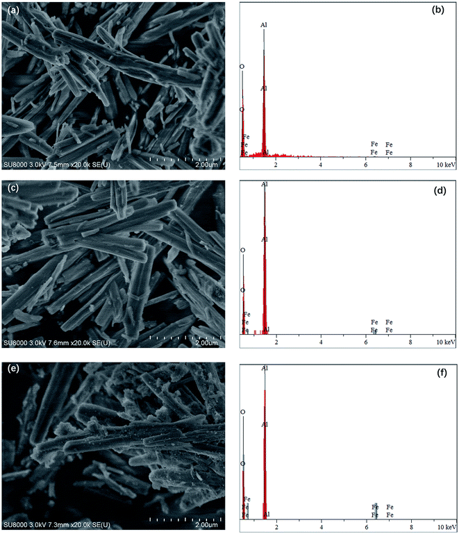 | ||
Fig. 1 SEM images and corresponding EDX patterns of different mole ratio Fe–Al composite oxides: (a) and (b) 1![[thin space (1/6-em)]](https://www.rsc.org/images/entities/char_2009.gif) : :![[thin space (1/6-em)]](https://www.rsc.org/images/entities/char_2009.gif) 100, (c) and (d) 5 100, (c) and (d) 5![[thin space (1/6-em)]](https://www.rsc.org/images/entities/char_2009.gif) : :![[thin space (1/6-em)]](https://www.rsc.org/images/entities/char_2009.gif) 100, and (e) and (f) 10 100, and (e) and (f) 10![[thin space (1/6-em)]](https://www.rsc.org/images/entities/char_2009.gif) : :![[thin space (1/6-em)]](https://www.rsc.org/images/entities/char_2009.gif) 100. 100. | ||
The wide angle XRD patterns of the Fe–Al composite oxides are shown in Fig. 2. The samples displayed peak characteristics of the Al2O3 phase (JCPDS 00-050-0741) and the Fe3O4/Fe2O3 phases (JCPDS 01-075-0449 and JCPDS 01-089-0596). Besides the dominated γ-Al2O3 phases, little Fe3O4/Fe2O3 phases were formed in Fe–Al-5 and -10. The XRD patterns showed a gradual increase in the intensity of ferric diffraction peak as the ferric content of the composites increased. Similar changes have also been reported in the XRD patterns of mesoporous iron-based spinels and synthetic Fe–Al composite oxides.33,34 Table 1 provides a summary of the parameters used for the BET experiments involving the three different Fe–Al composites. The results revealed that FeAl-10 had the largest surface area at 108 m2 g−1, followed sequentially by FeAl-5 and FeAl-1, which had surface areas of 98 and 89 m2 g−1, respectively. These pore structure data showed that the specific surface areas of the composites increased with increasing ferric content, whereas the pore diameter and pore volume decreased.
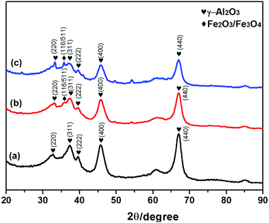 | ||
| Fig. 2 XRD patterns of iron and aluminum composite oxides with different mole ratios of (a) 1%, (b) 5% and (c) 10%. | ||
n(Fe)![[thin space (1/6-em)]](https://www.rsc.org/images/entities/char_2009.gif) : :![[thin space (1/6-em)]](https://www.rsc.org/images/entities/char_2009.gif) n(Al) n(Al) |
1% | 5% | 10% |
|---|---|---|---|
| Surface area (m2 g−1) | 89 | 98 | 108 |
| Pore volume (mL g−1) | 0.18 | 0.17 | 0.21 |
| Pore diameter (nm) | 5.50 | 3.73 | 3.78 |
3.2 Activity analysis
The activities of the three different composite materials were evaluated based on their degradation efficiencies (DgE). Fig. 3 shows the DgE values of CN-27 over the different Fe–Al composites after 1 h at 300 °C. Notably, the degradation efficiency of the FeAl-5 reaction system reached up to 93.0 ± 1.2%, which was close to that of FeAl-10 system (90.2 ± 1.4%). In contrast, the FeAl-1 system showed a much lower DgE value of 38.7 ± 1.4% when the reaction was conducted under the same conditions. The reactivity of these systems therefore followed the order FeAl-5 ≈ FeAl-10 ≫ FeAl-1. Besides, the dechlorination efficiencies of Fe–Al-1, Fe–Al-5 and Fe–Al-1 were observed to be 31.2%, 53% and 46.6% respectively. Patra et al. reported TiO2–Fe2O3 mixed oxides' efficient dehalogenation to the aromatic chloride-ring and found that iron(III) allow better activation of carbon bonds, which may explain the better performance of Fe–Al-5 and Fe–Al-10.29 The reactivities of a material is largely dependent on the number of active sites available on the surface of the catalyst, which is generally dependent on several factors, including the surface area, pore volume and phase composition. Fan et al. reported that catalysts with high BET surface areas and high pore volumes can exhibit higher activities than those with smaller values for these parameters.35 Su et al. reported that the enhanced performance of Ce0.2TiAlαOx towards the decomposition of 1,2,4-trichlorobenzene and nitrogen oxides could be attributed to its unique structural properties, resulting from the deposition of Al species and more Ce species, leading to greater interactions between the different phases.36 With this in mind, we speculated that the higher surface areas and enhanced interactions between the γ-Al2O3 and Fe3O4/Fe2O3 phases could contribute to higher reactivity of FeAl-5 and FeAl-10 compared with FeAl-1.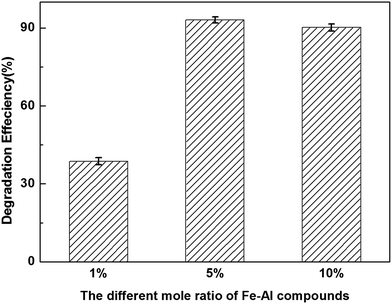 | ||
| Fig. 3 Degradation efficiencies of CN-27 over series mole ratios of iron and aluminum composite oxides. | ||
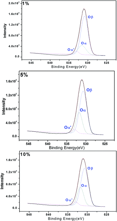
Reactive oxygen species are also believed to be involved in the activity of these systems.33 With this in mind, we investigated the surfaces of the composite oxides by X-ray photoelectron spectroscopy (XPS). The results shown in Fig. 4 revealed three peaks (Oβ, Oα, Oα′) immediately after the Gauss peak separation, which were attributed to the nucleophilic oxygen (O2−), electrophilic oxygen (O2– and O–) and adsorbed oxygen (O2) species in the lattice, with the peak located in bonding energy of 530.7 eV, 531.7 eV and 533.0 eV respectively. Electrophilic oxygen species (i.e., O2– and O–) can attack the electron clouds of high-density organic molecules, resulting in damage to organic carbon structures. We speculated that the presence of active oxygen species on the surfaces of the catalysts prepared in the current study could contribute to the reactions occurring during the degradation of CN-27.37–39 In this study, the proportions of electrophilic oxygen (Oα) observed on the FeAl-1, FeAl-5 and FeAl-10 composites were calculated as 20.4%, 33.9% and 28.1%, respectively. The higher ratios of electrophilic oxygen (O2– and O–) observed in the FeAl-5 and FeAl-10 materials could therefore explain why these materials showed higher reactivity toward the degradation of CN-27 than FeAl-1. In addition, XPS characterization could be also used to confirm the composition of the elements and their valent state in the as-prepared Fe–Al–O nanoshpere (see Fig. S1†).
3.3 PCN product identification and involved mechanism compared to that of CN-75
In the former study, we investigated the hydrodechlorination of two-side fully-chlorinated CN-75, and revealed that it preferentially began at its α-position.30 To develop a comprehensive understanding of the hydrodechlorination pathways of PCNs, we also investigated the PCN products resulting from the decomposition of CN-27 featuring fully chlorinated ring only at one side. Fig. 5 shows the GC-MS chromatograms of the samples obtained following the degradation of CN-27 in the presence of the FeAl-1, FeAl-5 and FeAl-10 reaction systems at 300 °C after 1 h. The products were identified based on a comparison of their mass spectra data with those found in the NIST02.L spectral database, as well as a comparison of their retention times with those of several standards. As listed in Table 2, a series of PCN products were identified following this process, including pentachloronaphthalenes (PeCNs), tetrachloronaphthalenes (TeCNs), trichloronaphthalenes (TrCNs), dichloronaphthalenes (DiCNs) and monochloronaphthalenes (MoCNs). The specific congeners included 1,2,3,4,6-PeCN (CN-50), 1,2,4,6/7-TeCN (CN-33/34), 1,2,3-TrCN (CN-13), 1,2,4-TrCN (CN-14), 2,3-DiCN (CN-10), 1,2-DiCN (CN-3), 1,4-DiCN (CN-5), 1,3-DiCN (CN-4), 2-MoCN (CN-2) and 1-MoCN (CN-1). The total amount of TrCNs observed during the degradation of CN-27 over the FeAl-5 reaction system reached up to 551 nmol, which was similar to the value of 588 nmol observed for FeAl-10. In contrast, the FeAl-1 system gave a much lower amount of 180.3 nmol. The total amounts of DiCNs and MoCNs produced during the degradation of CN-27 over the FeAl-5 system were 141.7 and 20.63 nmol, respectively. The FeAl-10 system gave smaller values of 112.8 and 7.32 nmol, respectively, whereas the FeAl-1 system afforded none of these degradents. Besides the series PCN products, the cracking products such as formic acid and acetic acid were also observed indicating the occurrence of oxidation pathway (see Fig. S2†).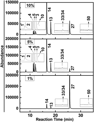 | ||
| Fig. 5 GC-MS chromatograms obtained from the degradation of CN-27 over Fe–Al composite oxides synthesized with different mole ratios. | ||
| Products | n(Fe)![[thin space (1/6-em)]](https://www.rsc.org/images/entities/char_2009.gif) : :![[thin space (1/6-em)]](https://www.rsc.org/images/entities/char_2009.gif) n(Al) n(Al) |
||
|---|---|---|---|
| 1% | 5% | 10% | |
| 1-MoCN(CN-1) | ND | 3.13 | 1.42 |
| 2-MoCN(CN-2) | ND | 17.5 | 5.9 |
| 1,3-DiCN(CN-4) | ND | 43.4 | 33.6 |
| 1,4-DiCN(CN-5) | ND | 37.8 | 28.4 |
| 1,2-DiCN(CN-3) | ND | 35.9 | 30 |
| 2,3-DiCN(CN-10) | ND | 24.6 | 20.8 |
| 1,2,4-TrCN(CN-14) | 129 | 428 | 446 |
| 1,2,3-TrCN(CN-13) | 51.3 | 123 | 142 |
| 1,2,4,6/7-TeCN(CN-33/34) | 36.2 | 60 | 68 |
| 1,2,3,4-TeCN(CN-27) | 922 | 104 | 147 |
| 1,2,3,4,6-PeCN(CN-50) | 1.04 | ND | 0.54 |
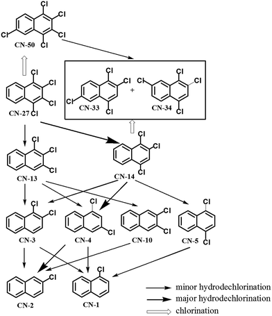
With the identification of the intermediates, the possible hydrodechlorination and chlorination pathways were traced as shown in Fig. 6. The detection of the newly formed lower chlorinated naphthalenes (i.e. TrCNs, DiCNs and MoCNs) indicated the occurrence of successive reductive hydrodechlorination reactions during the degradation of CN-27 over the Fe–Al composite oxides prepared in the current study. A similar successive reductive hydrodechlorination pathway was also observed during the degradation of CN-75 over micro/nano Fe3O4.30 The reverse chlorination pathway was observed with the detection of the TeCN isomers (i.e. CN-33/34) and PeCN congener (i.e. CN-50).
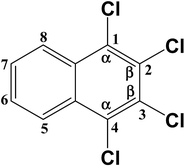
Two TrCN isomers (i.e., CN-13 and CN-14) were identified during the first hydrodechlorination step, which were likely produced by the dechlorination of the CN-27 at its α- and β-positions, respectively. However, the CN-14 contents of the samples resulting from the degradation of CN-27 over the FeAl-1, FeAl-5 and FeAl-10 reaction systems were 71.5%, 77.7% and 75.9% of the total TrCN (i.e., both isomers) contents, respectively. This result indicated that remarkably high levels of CN-14 than CN-13 were being generated during the first step of this degradation reaction. To develop a deeper understanding of the discrepancy observed between the experimental yields of the two TrCNs, we calculated the C–Cl bond dissociation energies (BDEs) of the parent molecule CN-27 using density functional theory (DFT), as shown in Table 3. The BDE of the C–Cl bond at the α-position of CN-27 was determined to be 385.346 kJ mol−1, slightly higher than the value for the C–Cl bond at the β-position, which was found to be 380.417 kJ mol−1. This result indicated that it would be easier to break the C–Cl bond at the β-position of CN-27 than the C–Cl bond at the α-position. Zhai et al. reported the standard energy of formation (ΔH0f) and the standard free energy of formation (ΔG0f) values of 75 polychlorinated naphthalenes using a DFT method.32,40 In this study, the ΔH0f and ΔG0f values of CN-13 were determined to be 206.41 and 292.48 kJ mol−1, respectively, which were both higher than the values of 197.82 and 283.71 kJ mol−1 determined for CN-14. These data are consistent with the experimental results observed for the different amounts of the two TrCN isomers (i.e. CN-14 > CN-13). However, this result is different from the result observed for the first step in the hydrodechlorination reaction of CN-75, where the CN-73 content of the material obtained following the dechlorination of CN-75 at its α-position was much higher than that of the CN-74 content resulting from the dechlorination of CN-75 at its β-position.30 This difference could be attributed to steric effects resulting from the surrounding atoms in the fully chlorinated structure of CN-27 versus CN-75. Taken together, these results suggest that the structural differences between two-side fully-chlorinated aromatic rings and one-side fully-chlorinated aromatic rings could have a pronounced impact on the dechlorination pathway.
During the second step of the hydrodechlorination reaction, we observed the formation of four DiCN isomers, including CN-10, CN-3, CN-5 and CN-4. The content of CN-4 with the lower ΔH0f and ΔG0f reported at 204.95 kJ mol−1 and 285.29 kJ mol−1 exceeded the other three by taking 30.6% and 29.8% of total amount of four DiCN isomers at FeAl-5 and FeAl-10 reaction systems respectively.40 In contrast, no DiCN isomers were detected in the FeAl-1 reaction system. The differences observed in the contents of the DiCN isomers were small compared with those of the TrCN isomers. However, we observed the formation of two MoCN isomers (i.e. CN-1 and CN-2) when the time allowed for the hydrodechlorination reaction step was extended. Furthermore, the thermodynamically stable isomer CN-2 with reported ΔH0f and ΔG0f of 225.13 kJ mol−1 and 300.39 kJ mol−1 represented 84.8% and 80.6% of the total MoCN contents following the degradation of CN-27 over the FeAl-5 and FeAl-10 reaction systems respectively.40 It is noteworthy, however, that we did not observe any MoCN isomers when we conducted the degradation of CN-27 over the FeAl-1 reaction system.
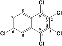
Trace amounts (0.54 and 1.04 nmol) of the PeCN congener CN-50 were also produced during the degradation of CN-27 over the FeAl-1 and FeAl-10 reaction systems, respectively. Considering its structure, CN-50 would most likely be produced by the chlorination of CN-27 at its 6- or 7-position. However, it would not be possible to distinguish between these different chlorination reactions during the degradation of CN-75 over the Fe3O4 because of the fully chlorinated structure of the parent compound.30 The degradation of CN-27 would lead to the formation of CN-33 and CN-44, which are structural isomers of CN-27. It is possible that CN-33 and CN-34 could be produced by the chlorination of CN-14 at its 6- or 7-position or the dechlorination of CN-50 at its 2- or 3-position, respectively. However, the contents of these congeners were determined to be in the range of 36.2–68 nmol, which is much higher than that of CN-50. The C–Cl bonds energy were investigated to explain the yields difference as listed in Table 3, which depends on the rates of formation and consumption of these compounds. The energy required for the formation of CN-50 via the chlorination of CN-27 at its 6- or 7-position was determined to be 392.878 kJ mol−1. This value was very close to the energy values required for the formation of CN-33 and CN-34 via the chlorination of CN-14 at 6- and 7-positions, which were with 393.714 and 392.878 kJ mol−1, respectively. This indicates the similar formation ratio of CN-33/34 and CN-50. On the other hand, the calculated BDEs for the C–Cl bonds at the 1-, 2-, 3- and 4-positions of CN-50 were much lower at 386.183, 380.744, 380.326 and 386.183 kJ mol−1 than that of 1-, 2- and 4-positions of CN-33 and CN-34 at 389.945, 388.275 and 391.204 kJ mol−1, and 391.204, 388.275 and 391.204 kJ mol−1, respectively. This indicates the easier consumption via the dechlorination pathway of CN-50 compared with CN-33/34. Their similar formation and discriminating consumption ratio gives an explanation to their content difference. Especially, the much lower BDEs at 2- or 3-position of CN-50 may result in the occurrence of CN-50 → CN-33/34 with the case of the cleavage of these C–Cl bonds, which makes a further contribution to their yield difference.
With the identification of products, the reaction pathways of CN-27 over the Fe–Al composite oxides were able to be traced. An occurrence of the successive hydrodechlorination reaction could be reflected by CN-27 → TrCNs (CN-13 and CN-14) → DiCNs (CN-3, CN-4, CN-5 and CN-10) → MoCNs (CN-1 and CN-2). The major hydrodechlorination pathway was determined by identifying the major products at each stage. According to the yield of the PCN products as listed in Table 2, it was judged that major hydrodechlorination pathway was: CN-27 → CN-14 → CN-4 → CN-2. The reverse chlorination reaction also happened while the hydrodechlorination reaction was occurring. CN-50 and CN-33/34 would most likely be produced by the chlorination of CN-27 and CN-14, respectively.
4. Conclusion
Varying mole ratio of rod-like Fe–Al composite oxide materials were prepared using an ethylene-glycol-mediated method combined with impregnation-burning synthesis. The degradation of the model compound CN-27 featuring one-side fully-chlorinated aromatic ring, was performed over as-prepared Fe–Al composite oxides. The results revealed that the reactivities were of the order FeAl-5 ≈ FeAl-10 ≫ FeAl-1. This order was largely affected by the pore structures and surface active sites difference shown in the BET test and XPS analysis. This influence may result from the mutual interaction between the Fe and Al species in the composite structures. Series products from PeCNs to MoCNs congeners were generated in the different reaction systems, suggesting the occurrence of successive hydrodechlorination and side chlorination pathways. Among the two isomers of TrCNs generated in the first-step dechlorination, the amount of CN-14 exceeded that of CN-13 from 71.5% to 77.7% across the three different systems. This suggested that the onset of hydrodechlorination producing lower chlorinated naphthalenes (CNs) is more favored on the β-position than the α-position, whereas the two-side fully chlorinated aromatic structure of CN-75 would favor hydrodechlorination at the α-position over Fe3O4. The structural differences between two-side fully-chlorinated aromatic rings and one-side fully-chlorinated aromatic rings would have a pronounced impact on the dechlorination pathway. According to the yield of the PCN products, it was judged that major hydrodechlorination pathway was: CN-27 → CN-14 → CN-4 → CN-2. Additionally, the detected CN-50 and CN-33/34 suggested the reverse chlorination reaction also happened while the hydrodechlorination reaction was occurring. The C–Cl BDEs of the parent and daughter PCN congener were calculated using DFT, to achieve a deeper understanding of the discrepancy observed between the experimental yields of the products.Acknowledgements
This study was supported by the National Natural Science Foundation of China (21377147, 21677163, 21321004), State's Key Project of Research and Development Plan (2016YFC0202500), the National 973 Program (2015CB453103), the Strategic Priority Research Program of the Chinese Academy of Sciences (XDB14020102) and Youth Innovation Promotion Association CAS.References
- T. F. Bidleman, P. A. Helm, B. M. Braune and G. W. Gabrielsen, Sci. Total Environ., 2010, 408, 2919–2935 CrossRef CAS PubMed
.
- X. Jiang, G. Liu, M. Wang and M. Zheng, Sci. Rep., 2015, 5, 13903 CrossRef PubMed
.
- G. Liu and M. Zheng, Environ. Sci. Technol., 2013, 47, 8093–8094 CAS
.
- Seventh meeting of the Persistent Organic Pollutants Review Committee., http://chm.pops.int/TheConvention/ThePOPs/TheNewPOPs/tabid/2511/Default.aspx, accessed June 2016.
- J. Falandysz, Environ. Pollut., 1998, 101, 77–90 CrossRef CAS PubMed
.
- J. Falandysz, B. Strandberg, L. Strandberg, P.-A. Bergqvist and C. Rappe, Sci. Total Environ., 1997, 204, 97–106 CrossRef CAS PubMed
.
- H. Park, J.-H. Kang, S.-Y. Baek and Y.-S. Chang, Environ. Pollut., 2010, 158, 1420–1427 CrossRef CAS PubMed
.
- Z. Nie, M. Zheng, W. Liu, B. Zhang, G. Liu, G. Su, P. Lv and K. Xiao, Chemosphere, 2011, 85, 1707–1712 CrossRef CAS PubMed
.
- R. G. M. Lee, P. Coleman, J. L. Jones, K. C. Jones and R. Lohmann, Environ. Sci. Technol., 2005, 39, 1436–1447 CrossRef CAS PubMed
.
- J. Falandysz, Food Addit. Contam., 2003, 20, 995–1014 CrossRef CAS PubMed
.
- Y. Ishikawa, J. Falandysz, Y. Noma and S. Sakai, J. Environ. Sci. Health, Part A, 2005, 40, 2171–2187 CrossRef CAS PubMed
.
- L. Guo, B. Te and H. Zheng, Progr. Chem., 2009, 21, 377–388 CAS
.
- D. L. Villeneuve, K. Kannan, J. S. Khim, J. Falandysz, V. A. Nikiforov, A. L. Blankenship and J. P. Giesy, Arch. Environ. Contam. Toxicol., 2000, 39, 273–281 CrossRef CAS PubMed
.
- G. Su, Q. Li, H. Lu, L. Zhang, L. Huang, L. Yan and M. Zheng, Sci. Rep., 2015, 5, 17800 CrossRef PubMed
.
- Y. Sun, X. Liu, M. Kainuma, W. Wang, M. Takaoka and N. Takeda, Chemosphere, 2015, 137, 78–86 CrossRef CAS PubMed
.
- X. D. Ma, X. Feng, X. He, H. W. Guo, L. Lv, J. Guo, H. Q. Cao and T. Zhou, Microporous Mesoporous Mater., 2012, 158, 214–218 CrossRef CAS
.
- Y. Nomura, S. Aono, T. Arino, T. Yamamoto, A. Terada, Y. Noma and M. Hosomi, Chemosphere, 2013, 93, 2657–2661 CrossRef CAS PubMed
.
- X. Ma, M. Zheng, W. Liu, Y. Qian, B. Zhang and W. Liu, J. Hazard. Mater., 2005, 127, 156–162 CrossRef CAS PubMed
.
- L. Zhang, M. Zheng, B. Zhang, W. Liu, L. Gao, T. Ba, Z. Ren and G. Su, J. Environ. Sci., 2008, 20, 1523–1526 CrossRef CAS
.
- S. Mota, M. Abon, J. C. Volta and J. A. Dalmon, J. Catal., 2000, 193, 308–318 CrossRef CAS
.
- M.-F. Yu, W.-W. Li, X.-D. Li, X.-Q. Lin, T. Chen and J.-H. Yan, Chemosphere, 2016, 156, 383–391 CrossRef CAS PubMed
.
- L. Huang, G. Su, Y. Liu, L. Li, S. Liu, H. Lu and M. Zheng, RSC Adv., 2014, 4, 25453 RSC
.
- L. Zhang, M. Zheng, W. Liu, B. Zhang and G. Su, J. Hazard. Mater., 2008, 150, 831–834 CrossRef CAS PubMed
.
- M. H. Schoonenboom, H. E. Zoetemeijer and K. Olie, Appl. Catal., B, 1995, 6, 11–20 CrossRef CAS
.
- P. Souza Santos, H. Souza Santos and S. P. Toledo, Mater. Res., 2000, 3, 104–114 Search PubMed
.
- M. M. Ivey, K. A. Layman, A. Avoyan, H. C. Allen and J. C. Hemminger, J. Phys. Chem. B, 2003, 107, 6391–6400 CrossRef CAS
.
- B. Li, H. Yuan, P. Yang, B. Yi and Y. Zhang, Ceram. Int., 2016, 42, 17405–17409 CrossRef CAS
.
- J. R. Sohn and D. H. Seo, Catal. Today, 2003, 87, 219–226 CrossRef CAS
.
- A. K. Patra, A. Dutta and A. Bhaumik, ACS Appl. Mater. Interfaces, 2012, 4, 5022–5028 CAS
.
- G. Su, H. Lu, L. Zhang, A. Zhang, L. Huang, S. Liu, L. Li and M. Zheng, Environ. Sci. Technol., 2014, 48, 6899–6908 CrossRef CAS PubMed
.
- H. Lu, Q. Li, G. Su, M. Zheng, Y. Zhao, X. Miao, Y. Liu, X. Huang and Y. Zhao, Environ. Sci.: Nano, 2017 10.1039/C6EN00662K
.
- M. J. Frisch, G. W. Trucks, H. B. Schlegel, G. E. Scuseria, M. A. Robb, J. R. Cheeseman, V. G. Zakrzewski, J. A. Montgomery, R. E. Stratmann, J. C. Burant, S. Dapprich, J. M. Millam, A. D. Daniels, K. N. Kudin, M. C. Strain, O. Farkas, J. Tomasi, V. Barone, M. Cossi, R. Cammi, B. Mennucci, C. Pomelli, C. Adamo, S. Clifford, J. Ochterski, G. A. Petersson, P. Y. Ayala, Q. Cui, K. Morokuma, D. K. Malick, A. D. Rabuck, K. Raghavachari, J. B. Foresman, J. Cioslowski, J. V. Ortiz, A. G. Baboul, B. B. Stefanov, G. Liu, A. Liashenko, P. Piskorz, I. Komaromi, R. Gomperts, R. L. Martin, D. J. Fox, T. Keith, M. A. AlLaham, C. Y. Peng, A. Nanayakkara, M. Challacombe, P. M. W. Gill, B. Johnson, W. Chen, M. W. Wong, J. L. Andres, C. Gonzalez, M. Head-Gordon, E. S. Replogle and J. A. Pople, GAUSSIAN 98, Revision A.9., Gaussian, Inc., Pittsburgh, PA, 1998 Search PubMed
.
- L. Huang, G. Su, A. Zhang, Y. Shi, C. Xia, H. Lu, L. Li, S. Liu and M. Zheng, J. Hazard. Mater., 2013, 261, 451–462 CrossRef CAS PubMed
.
- F. Yang, Q. Li, G. Su, X. Huang, B. Li, Y. Zhao, X. Miao and M. Zheng, Chemosphere, 2016, 150, 445–452 CrossRef CAS PubMed
.
- Y. Fan, X. Lu, Y. Ni, H. Zhang, M. Zhu, Y. Li and J. Chen, Appl. Catal., B, 2011, 101, 606–612 CrossRef CAS
.
- G. Su, L. Huang, S. Liu, H. Lu, F. Yang and M. Zheng, Catal. Sci. Technol., 2015, 5, 1041–1051 CAS
.
- J. C. Dupin, D. Gonbeau, P. Vinatier and A. Levasseur, Phys. Chem. Chem. Phys., 2000, 2, 1319–1324 RSC
.
- X. Ma, X. Feng, J. Guo, H. Cao, X. Suo, H. Sun and M. Zheng, Appl. Catal., B, 2014, 147, 666–676 CrossRef CAS
.
- J. P. Bonnelle, B. Delmon and E. Derouane, Surface Properties and Catalysis by Non-Metals, Reidel, Dordrecht, 1983 Search PubMed
.
- Z. Zhai and Z. Wang, J. Mol. Struct., 2005, 724, 221–227 CrossRef CAS
.
Footnote |
| † Electronic supplementary information (ESI) available: [DETAILS]. See DOI: 10.1039/c7ra01775h |
| This journal is © The Royal Society of Chemistry 2017 |

