 Open Access Article
Preparation of functionalized partially unzipped carbon nanotube/polyimide composite fibers with increased mechanical and thermal properties†
Yao Cheng,
Shiyu Zhang,
Juan Li,
Jun Sun,
Jianjun Wang,
Chuanxiang Qin and
Lixing Dai *
*
College of Chemistry, Chemical Engineering and Materials Science, Soochow University, Suzhou, Jiangsu 215123, People's Republic of China. E-mail: dailixing@suda.edu.cn; Fax: +86-0512-65883354; Tel: +86-0512-65883354
First published on 19th April 2017
Abstract
Partially unzipped carbon nanotubes (PUCNTs) were prepared via a facile longitudinal unzipping method and then covalently bonded with 4,4′,4′′-triaminotriphenylamine (TAPA) for the first time to obtain functionalized PUCNTs (f-PUCNTs). Polyamide acid (PAA)-based composites with f-PUCNTs were prepared by using in situ polymerization, and the f-PUCNTs/PAA composite solution was wet-spun to obtain composite fibers which were finally transferred into f-PUCNTs/PI composite fibers after heat treatment. f-PUCNTs not only combined the advantages of carbon nanotubes and graphene, but also possessed groups which could covalently bond with the PI matrix, leading to a relatively strong reinforcing effect on the matrix. The tensile strength and Young's modulus of the composite fiber containing 1.0 wt% f-PUCNTs increased to 165% and 208% relative to those of PI fiber, respectively, and to 137% and 153% relative to those of the composite fiber containing the same amount of PUCNTs, respectively. Meanwhile, the thermal properties also increased obviously, e.g. the 5% weight loss temperature and glass transition temperature of the composite fiber containing 1.0 wt% f-PUCNTs were 50 °C and 13 °C higher than those of PI fiber, respectively.
1. Introduction
As an important member of high-performance fibers, polyimide (PI) fiber1 not only possesses excellent mechanical properties, but also shows excellent thermal stability, chemical resistance and so on. These properties make it dominant in many application fields, such as high temperature filtration, flame retardant protection, fiber reinforcement, wear resistance and electromagnetic shielding. However, due to the limitation of the polymer synthesis and fiber formation process, the properties of PI fiber cannot reach the values calculated theoretically, which largely restricts its application.To improve the properties of PI, the addition of reinforcements, such as clays,2,3 metal nanoparticles4,5 and carbon nanomaterials,6 as an efficient and economical approach, has been widely studied in recent decades. Particularly, carbon nanotubes (CNTs)7–12 and graphene13–15 attracted people's great attentions for their unique performance. The majority of the research effort has been concentrated on the reinforcement of either CNTs or graphene to polymer matrix and the properties of the composites were improved to some extent. Ogasawara et al.7 reported 36–42% increase in elastic modulus and 25% increase in tensile strength with the addition of 1.0 wt% pure multi-wall carbon nanotubes (MWCNTs). Yin et al.10 prepared functionalized MWCNTs (f-MWCNTs)/PI composite fibers which showed increase in Young's modulus by 50% for a low f-MWCNTs loading (1.0 wt%) and increase in 5% weight loss temperature of 2.0 wt% f-MWCNTs/PI fiber by ∼16 °C. Compared with CNTs, graphene can be easily produced in large scale and narrow size distribution,16 and it can be easily dispersed in solvents or polymer matrix with strong interfacial interaction.17 Chen et al.13 introduced graphene oxide (GO) to PI matrix and found that the tensile strength and the 5% weight loss temperature increased from 87.5 MPa and 520 °C to 120 MPa and 560 °C, respectively. Even in our previous report, we successfully prepared siloxane-functionalized graphene oxide (DSX-GO)/PI composite films and the tensile strength reached 322 MPa at 1.0 wt% DSX-GO doping.18
Researchers showed more interest in the reinforcement caused by combination of two or more nanomaterials,19–22 and particularly the synergetic reinforcement of CNTs and graphene on polymer in recent years.23–26 Kumar et al.26 hybridized graphitic nanoplatelets (GNP) with MWCNTs in polyetherimide (PEI) composites. As compared with pure PEI film, the PEI-based composite film at a loading of 0.25 wt% GNP and 0.25 wt% MWCNTs showed 17% increase in the storage modulus. However, CNTs and graphene mixed simply in composites lack enough interaction between both nanomaterials in the composites in which CNTs and graphene were hard to disperse homogeneously. As reported,23,27 a single layer of CNTs has grown on the surface of graphene through chemical vapor deposition (CVD), which caused an improvement in the electrical or thermal conductivity of its composites with polymer. However, CVD method required metal catalyst, high temperature and horizontal quartz tube furnace, which brought about a plenty of difficulties such as metal impurity, high cost and complicated operation. In recent decade, researchers found a new approach to produce graphene nanoribbons28,29 from CNTs by cutting them longitudinally, and partially unzipped carbon nanotubes (PUCNTs) could be obtained by controlling the oxidative unzipping degree. Clearly, the approach to prepare PUCNTs was simple and economical, and no impurities existed in the products.28 PUCNTs possessed strong interface interaction between outer-wall graphene and inner-wall CNTs, which made PUCNTs become ideal reinforcements for reinforcing the composites. But in fact, graphene nanoribbons with high length-to-width ratio showed interesting electronic, magnetic and optical properties, so as the combination of graphene nanoribbons and CNTs, PUCNTs were also mostly investigated on these properties.30–32 Few work about the effect of PUCNTs on mechanical properties of composites has been reported. Liu et al.33 noticed the reinforcement effect of PUCNTs and fabricated thermoplastic polyurethane (TPU) composite films containing different PUCNTs loadings. Compared with the mechanical properties of pure TPU film, the tensile strength and Young's modulus of the TPU composite films were improved by 184% and 81%, respectively.
As reported, some functionalizations of CNTs, such as strong acid treatment34 and Friedel–Crafts reaction,35 provided covalent bond interaction between polymer chains and CNTs which showed more effective stress transfer from polymer matrix to CNTs than non-covalent bond interaction. Similarly, functionalization of PUCNTs would be beneficial to the stress transfer. Moreover, PUCNTs possess both large specific area of graphene and high aspect ratios of CNTs, which benefits not only to the interaction between PUCNTs and polymer matrix, but also to orientation of PUCNTs in composites, and therefore are quite suitable to be used as reinforcements of polymer fibers. However, till now no work on covalent functionalization of PUCNTs and their reinforcing effects on PI fibers has been reported.
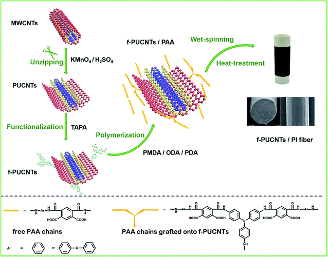
In this work, PUCNTs were prepared by longitudinally unzipping the outer wall of MWCNTs. Then 4,4′,4′′-triaminotriphenylamine (TAPA) reacted with the oxygen-containing groups of outer-wall graphene first time to form functionalized PUCNTs (f-PUCNTs) which provide reaction sites for the covalent connection with polyamide acid (PAA) matrix. Comparing with di-amine, introduction of tri-amine may increase the reaction sites of PAA grafting onto PUCNTs, benefiting to the grafting and thus to the interface interaction between the polymer and PUCNTs. Besides, PI fibers containing both 4,4′-diaminodiphenyl (ODA) and p-phenylenediamine (PDA) in a certain proportion showed higher strength and modulus than PI fibers containing solely ODA36 or solely PDA.37 Finally, a series of f-PUCNTs/PI composite fibers were prepared by wet spinning and thereafter heat treatment. The structure of f-PUCNTs and the mechanical properties of the composite fibers were mainly discussed, and the thermal properties of the composite fibers were also investigated.
2. Experimental section
2.1 Materials
MWCNTs (diameter: 10–30 nm; length: 20–30 μm) were purchased from Chengdu Organic Chemicals Co. Ltd. 4,4′-diaminodiphenyl (ODA, Aladdin), p-phenylenediamine (PDA, Aladdin), N-ethyl-N′-3-dimethylaminopropyl carbodiimide hydrochloride (EDC·HCl, Accela), N-hydroxysuccinimide (NHS, Shanghai Yuanye), 4,4′,4′′-triaminotriphenylamine (TAPA, Ark Pharm), anhydrous dimethylacetamide (DMAc, Sinopharm), dimethylformamide (DMF, Sinopharm), acetic anhydride (Sinopharm), pyridine (Sinopharm), potassium permanganate (KMnO4, Sinopharm), 98% sulfuric acid (H2SO4, Sinopharm), phosphoric acid (H3PO4, Sinopharm), hydrogen peroxide (H2O2, Sinopharm) and hydrochloric acid (HCl, Sinopharm) were used as received. Pyromellitic dianhydride (PMDA, Aladdin) was dried in a vacuum oven at 120 °C overnight to remove water thoroughly.2.2 Preparation of PUCNTs and f-PUCNTs
The preparation of PUCNTs was based on a ref. 31. 0.200 g MWCNTs, 50 ml concentrated H2SO4 and 6 ml H3PO4 were added in a 250 ml three-necked flask placed in an ice-water bath and were stirred for 1 h. After 0.600 g KMnO4 was added and the temperature was raised to 65 °C, the mixture was reacted for 2 h and cooled to room temperature. Then, 200 ml ice water and 10 ml H2O2 (30%) were added to the mixture to remove residual KMnO4, and the new mixture was centrifuged and washed with diluted hydrochloric acid (5% HCl) and distilled water several times until pH of the obtained PUCNTs suspension was neutral. The suspension was freeze dried into PUCNTs powders in a vacuum freeze-drying equipment for 48 h.0.100 g PUCNTs were dispersed in 25 ml DMF by sonication for 0.5 h and then 0.575 g EDC·HCl and 0.342 g NHS were added to the solution. After stirring for 1 h, 0.200 g TAPA was added and the solution was stirred for 6 h at room temperature. Afterwards, the solution was filtered and washed with DMF and distilled water several times to remove the activating agents and residual TAPA. Finally, f-PUCNTs were dispersed in distilled water and the suspension was freeze dried into f-PUCNTs powders overnight.
2.3 Preparation of f-PUCNTs/PI composite fibers
As shown in Scheme 1, the typical preparation procedure of f-PUCNTs/PI composite fiber containing 1.0 wt% f-PUCNTs was as follows. 0.060 g f-PUCNTs was dispersed in 40 ml DMAc by sonication for 0.5 h and then 2.403 g ODA and 0.324 g PDA were added to the solution in a three-necked flask which was stirred under nitrogen atmosphere in an ice-water bath. Polyamide acid (PAA) was obtained through addition of 3.304 g PMDA and reaction for 2 h, and then 1.022 g acetic anhydride and 0.792 g pyridine were added to obtain partially imidized PAA. The mixture kept stirred for 3 h and the spinning solution of the imidized PAA composite with a loading of 1.0 wt% f-PUCNTs was prepared.The imidized PAA composite fiber containing 1.0 wt% f-PUCNTs was prepared by wet spinning with a small-sized spinning apparatus. The spinning solution was extruded by air and coagulated in the mixed solution of water and methanol. The as-spun fiber was heat treated at 100, 200, 300 and 350 °C continually and stretched at 400 °C to obtain the f-PUCNTs/PI composite fiber. Similarly, f-PUCNTs/PI composite fibers with different loadings of f-PUCNTs (0, 0.5, 1.5 and 2 wt%) were prepared according to above process. For comparison, 1.0 wt% MWCNTs/PI composite fiber and 1.0 wt% PUCNTs/PI composite fiber were also prepared.
2.4 Characterization
The structures of PUCNTs and f-PUCNTs were analyzed using Raman spectroscope equipped with a 514 nm laser source (Horiba, LabRAMHR800) and X-ray diffractometer (PANalytical, X'Pert-Pro MPD) with Cu Kα radiation (λ = 0.154 nm). The reactions between TAPA and PUCNTs were confirmed by Fourier transfer infrared spectroscope (FT-IR, Thermo Scientific, Nicolet 6700) and X-ray photoelectron spectroscopy (XPS, AXIS-NOVA, Kratos). The surface morphologies of MWCNTs, PUCNTs, f-PUCNTs and f-PUCNTs grafted by PAA chains were performed on a transmission electron microscope (TEM, Tecnai, G2 20). The structures of PI and its composite fibers were characterized with Raman spectroscope equipped with a 785 nm laser source (Horiba, LabRAMHR800). The thermal properties of f-PUCNTs/PI composite fibers were measured by Discovery thermal gravimetric analyzer (TGA, TA Instruments, Discovery) under nitrogen gas flow at a heating rate of 10 °C min−1 and dynamic mechanical analyzer (DMA, TA Instruments, Q800) at a heating rate of 5 °C min−1 and a frequency of 1 Hz. The mechanical properties of PI-based composite fibers were measured with HD021N fiber strength instrument at a tensile speed of 1 mm min−1 and each of fiber samples was measured ten times. The morphologies of fracture and longitudinal surface of f-PUCNTs/PI composite fibers were performed on a field-emission scanning electron microscope (SEM, Hitachi, S-4800).3. Results and discussion
3.1 Chemical and structural analyses of PUCNTs and f-PUCNTs
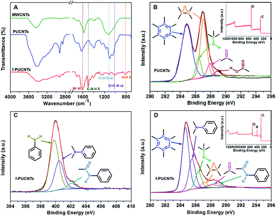
As shown in Fig. 1A, for the peaks of oxygenic groups in the FT-IR spectrum of PUCNTs, except there are bands assigned to C![[double bond, length as m-dash]](https://www.rsc.org/images/entities/char_e001.gif) O stretching vibration at 1704 cm−1, O–H stretching vibration near 3400 cm−1, O–H deformation vibration at 1380 cm−1 and C–O–C stretching vibration at 1100 cm−1 as in that of MWCNTs, new bands attributed to C–O–C asymmetric stretching vibration and C–O–H in-plane stretching vibration appear at 1180 cm−1 and 1250 cm−1, respectively. These changes indicate that a large number of carboxyl, hydroxyl and epoxy groups exist on the outer wall of PUCNTs.32 And furthermore, the appearance of C–H stretching vibration band at 2921 cm−1 and 2851 cm−1 and C–H in-plane stretching vibration band at 1050 cm−1 in the spectrum of PUCNTs also reveals the disruption of surface π-conjugated structure.12 In addition, due to the disruption, oxygenic groups can induce polarization of electronic density of benzene rings, which makes the absorption of benzene ring at 1586 cm−1 shift to 1618 cm−1. Compared with PUCNTs, four new peaks at 1500 cm−1, 1314 cm−1, 1011 cm−1 and 810 cm−1 appear in the spectrum of f-PUCNTs, which correspond to C–N–H deformation vibration, C–N stretching vibration, O
O stretching vibration at 1704 cm−1, O–H stretching vibration near 3400 cm−1, O–H deformation vibration at 1380 cm−1 and C–O–C stretching vibration at 1100 cm−1 as in that of MWCNTs, new bands attributed to C–O–C asymmetric stretching vibration and C–O–H in-plane stretching vibration appear at 1180 cm−1 and 1250 cm−1, respectively. These changes indicate that a large number of carboxyl, hydroxyl and epoxy groups exist on the outer wall of PUCNTs.32 And furthermore, the appearance of C–H stretching vibration band at 2921 cm−1 and 2851 cm−1 and C–H in-plane stretching vibration band at 1050 cm−1 in the spectrum of PUCNTs also reveals the disruption of surface π-conjugated structure.12 In addition, due to the disruption, oxygenic groups can induce polarization of electronic density of benzene rings, which makes the absorption of benzene ring at 1586 cm−1 shift to 1618 cm−1. Compared with PUCNTs, four new peaks at 1500 cm−1, 1314 cm−1, 1011 cm−1 and 810 cm−1 appear in the spectrum of f-PUCNTs, which correspond to C–N–H deformation vibration, C–N stretching vibration, O![[double bond, length as m-dash]](https://www.rsc.org/images/entities/char_e001.gif) C–N stretching vibration and N–H twisting vibration, respectively. Meanwhile, the intensities of peak near 3400 cm−1, which contains O–H stretching vibration and N–H stretching vibration, and peak of C–O–C stretching vibration at 1100 cm−1 weaken obviously after the functionalization of PUCNTs. All of these differences between PUCNTs and f-PUCNTs indicate the reactions between the oxygenic groups of PUCNTs and amine groups of TAPA. At this stage, peak of benzene ring stretching vibration at 1618 cm−1 shifts to 1602 cm−1 because the reactions make the surface π-conjugated structure of f-PUCNTs partially recover.
C–N stretching vibration and N–H twisting vibration, respectively. Meanwhile, the intensities of peak near 3400 cm−1, which contains O–H stretching vibration and N–H stretching vibration, and peak of C–O–C stretching vibration at 1100 cm−1 weaken obviously after the functionalization of PUCNTs. All of these differences between PUCNTs and f-PUCNTs indicate the reactions between the oxygenic groups of PUCNTs and amine groups of TAPA. At this stage, peak of benzene ring stretching vibration at 1618 cm−1 shifts to 1602 cm−1 because the reactions make the surface π-conjugated structure of f-PUCNTs partially recover.
Using the deconvolution of C 1s peaks and N 1s peak in the XPS spectra of MWCNTs (Fig. S1A†), PUCNTs and f-PUCNTs (Fig. 1B–D), the composition of the sample surface and the interaction between PUCNTs and TAPA are revealed. More detailed data about element composition and percentage contribution of functional groups in the three samples are summarized in Fig. S1B and C.† MWCNTs are composed of 96.43% carbon and 3.57% oxygen, but the percentage of oxygen in PUCNTs obtained through oxidation of MWCNTs increases sharply to 30.76%, which means a plenty of oxygenic groups appear on the surface of PUCNTs. The XPS spectra can further support the results. The C 1s spectrum of MWCNTs can be divided into three peaks, i.e. a main peak at 284.7 eV is attributed to C–C/C![[double bond, length as m-dash]](https://www.rsc.org/images/entities/char_e001.gif) C and another two peaks at 286.0 eV and 287.0 eV reveal the existence of C–OH and C–O–C groups, respectively. However, the C 1s spectrum of PUCNTs is different from that of MWCNTs and shows five peaks at 284.8 eV, 286.4 eV, 287.0 eV, 287.9 eV and 288.9 eV, corresponding to C–C/C
C and another two peaks at 286.0 eV and 287.0 eV reveal the existence of C–OH and C–O–C groups, respectively. However, the C 1s spectrum of PUCNTs is different from that of MWCNTs and shows five peaks at 284.8 eV, 286.4 eV, 287.0 eV, 287.9 eV and 288.9 eV, corresponding to C–C/C![[double bond, length as m-dash]](https://www.rsc.org/images/entities/char_e001.gif) C, C–OH, C–O–C, C
C, C–OH, C–O–C, C![[double bond, length as m-dash]](https://www.rsc.org/images/entities/char_e001.gif) O and O
O and O![[double bond, length as m-dash]](https://www.rsc.org/images/entities/char_e001.gif) C–OH groups, respectively (Fig. 1B). Compared the XPS surveys of PUCNTs (inset in Fig. 1B) with f-PUCNTs (inset in Fig. 1D), the prominent change from PUCNTs to f-PUCNTs is the appearance of nitrogen. The C 1s spectrum of f-PUCNTs (Fig. 1D) shows a significant weakened C–O–C peak at 287.1 eV and two new peaks at 285.4 eV and 288.5 eV corresponding to C–N and O
C–OH groups, respectively (Fig. 1B). Compared the XPS surveys of PUCNTs (inset in Fig. 1B) with f-PUCNTs (inset in Fig. 1D), the prominent change from PUCNTs to f-PUCNTs is the appearance of nitrogen. The C 1s spectrum of f-PUCNTs (Fig. 1D) shows a significant weakened C–O–C peak at 287.1 eV and two new peaks at 285.4 eV and 288.5 eV corresponding to C–N and O![[double bond, length as m-dash]](https://www.rsc.org/images/entities/char_e001.gif) C–N groups, respectively. As shown in Fig. S1C,† the percentage of oxygen containing group C–O–C in f-PUCNTs decreases to only 4.48% from 31.25% (PUCNTs), while the percentage of newly appeared groups C–N and O
C–N groups, respectively. As shown in Fig. S1C,† the percentage of oxygen containing group C–O–C in f-PUCNTs decreases to only 4.48% from 31.25% (PUCNTs), while the percentage of newly appeared groups C–N and O![[double bond, length as m-dash]](https://www.rsc.org/images/entities/char_e001.gif) C–N in f-PUCNTs are up to 23.5% and 5.51%, respectively. Further, the N 1s spectrum of f-PUCNTs (Fig. 1C) shows three main peaks at 399.8 eV, 400.5 eV and 402.0 eV, attributing to N–H, C–N and O
C–N in f-PUCNTs are up to 23.5% and 5.51%, respectively. Further, the N 1s spectrum of f-PUCNTs (Fig. 1C) shows three main peaks at 399.8 eV, 400.5 eV and 402.0 eV, attributing to N–H, C–N and O![[double bond, length as m-dash]](https://www.rsc.org/images/entities/char_e001.gif) C–N groups, respectively. Consequently, the XPS spectra further indicate that TAPA reacts with the oxygenic groups on PUCNTs.
C–N groups, respectively. Consequently, the XPS spectra further indicate that TAPA reacts with the oxygenic groups on PUCNTs.
The weight loss curves of MWCNTs, PUCNTs and f-PUCNTs are shown in Fig. S2.† MWCNTs start to decompose at about 550 °C and the weight loss is only 7% at 800 °C. PUCNTs show dramatic weight loss between 100 and 300 °C due to thermal decomposition of oxygenic groups on the surface of PUCNTs. Introduction of TAPA to f-PUCNTs removes some of oxygenic groups on PUCNTs, so the thermal stability of f-PUCNTs increases instead. The weight loss of f-PUCNTs is lower than that of PUCNTs at all the temperature and the difference is up to 17% at 800 °C.
In order to further study the structures of PUCNTs and f-PUCNTs, Raman spectroscopy and XRD analyses are employed. As shown in Fig. 2A, the intensity ratio (ID/IG) of peak near 1344 cm−1 (D band), which is attributed to sp3-hybridized carbon atoms, to peak near 1579 cm−1 (G band), which is associated with sp2-hybridized carbon atoms, increases from 0.76 for MWCNTs to 0.99 for PUCNTs, indicating that many oxygen-containing groups are introduced to the outer wall of PUCNTs.32 Besides, the intensity of peak near 2693 cm−1 (2D band) in Raman spectrum of PUCNTs becomes weaker than that in the spectrum of MWCNTs due to the strong oxidation for the former. All of these changes demonstrate the destruction of uniform and ordering multi-layer structure of MWCNTs for PUCNTs.31 Raman spectrum of f-PUCNTs appears three new peaks of TAPA near 1138, 1391 and 1440 cm−1 compared with PUCNTs, reflecting that TAPA exists on the surface of f-PUCNTs. Meanwhile, the ratio of ID/IG for f-PUCNTs decrease to 0.91, which indicates decreasing of oxygenic groups and partially recovery of π-conjugated structure during the functionalization as stated above.
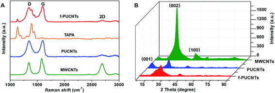 | ||
| Fig. 2 (A) Raman spectra of MWCNTs, PUCNTs, TAPA and f-PUCNTs. (B) X-ray diffraction patterns of MWCNTs, PUCNTs and f-PUCNTs. | ||
Fig. 2B shows the XRD patterns of MWCNTs, PUCNTs and f-PUCNTs. A strong peak at 26° and a weak peak at 42° appear in the spectrum of MWCNTs which is similar to that of graphite, corresponding to (002) with d spacing of 3.4 Å and (100) reflection of hexagonal graphite, respectively. And (002) is interlayer spacing of nanotubes8 and (100) peak is caused by the high degree of graphitization.38 Compared with the XRD pattern of MWCNTs, the peaks at 26° and 42° for PUCNTs become weaker and a new peak at 10.7° corresponding to (001) with d spacing of 8.3 Å reflection of graphene nanosheets appears, indicating the structural disruption of carbon nanotube, appearance of graphene nanosheets and increase of d spacing.33 The XRD pattern of f-PUCNTs shows a broad peak at 25.6° and disappearance of peak at 10.7°, indicating that many oxygenic groups are reacted with TAPA or removed from the outer-wall graphene of PUCNTs and the π–π stacking interaction between graphene and CNTs increases.28
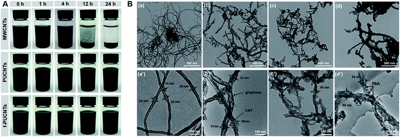
The dispersibility of nanofillers in solvent is crucial to prepare homogeneous PI-based composites with excellent performance. Fig. 3 shows the dispersions of MWCNTs, PUCNTs and f-PUCNTs dispersed in DMAc at 1 mg ml−1 after ultrasonication 0.5 h and standing for 0 h, 1 h, 4 h, 12 h and 24 h, respectively. MWCNTs in the dispersion show obvious precipitation over time, while PUCNTs and f-PUCNTs show distinctly improved dispersibility and no visible aggregation can be observed after standing for 24 h. TEM images of MWCNTs, PUCNTs, f-PUCNTs and f-PUCNTs grafted by PAA chains are shown in Fig. 3B. MWCNTs (Fig. 3B(a) and (a′)) show a strong trend to aggregate and the tubular structure with diameters near 10–30 nm. As shown in Fig. 3B(b) and (b′), the outer walls of PUCNTs are unzipped longitudinally to graphene nanosheets and the inner walls of PUCNTs still maintain tubular structure. PUCNTs have broader widths approximately 50–60 nm after longitudinal unzipping, whereas the diameters of f-PUCNTs (Fig. 3B(c) and (c′)) reduce due to the increased π–π stacking interaction between graphene and CNTs, which is consistent with the Raman and XRD results. As shown in Fig. 3B(d) and (d′), the diameters of f-PUCNTs grafted by PAA chains become greater than those of f-PUCNTs and many stains could be clearly seen in the outer surface of f-PUCNTs, which represents that a plenty of PAA chains are grafted to the f-PUCNTs because free PAA chains have been removed thoroughly.
3.2 Mechanical and thermal properties of f-PUCNTs/PI composite fibers
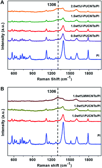
Raman spectra for PI-based composite fibers are shown in Fig. 4. The main characteristic bands of pure PI39,40 are summarized as follows: C–N–C transverse vibration stretching, 1124 cm−1; C–N–C axial stretching, 1390 cm−1; aromatic imide ring vibration, 1608 cm−1; aromatic ring vibration, 1510 cm−1; C![[double bond, length as m-dash]](https://www.rsc.org/images/entities/char_e001.gif) O symmetric stretching, 1788 cm−1. There are obvious changes with the addition of the nanofillers in the Raman spectra of PI-based composite fibers. The Raman scattering intensities of the characteristic bands reduce significantly with the increase of the loadings of f-PUCNTs (Fig. 4A) and similar trend can be observed in FT-IR spectra (Fig. S3†). As shown in Fig. 4B, at the same content of f-PUCNTs, PUCNTs and MWCNTs, the intensities of the spectra of their composites decrease gradually, for which the reason is that f-PUCNTs, PUCNTs and MWCNTs disrupt the homogeneous orientation structure of PI chains leading to weakening of Raman scattering41 and meanwhile absorb the visible and infrared light.32
O symmetric stretching, 1788 cm−1. There are obvious changes with the addition of the nanofillers in the Raman spectra of PI-based composite fibers. The Raman scattering intensities of the characteristic bands reduce significantly with the increase of the loadings of f-PUCNTs (Fig. 4A) and similar trend can be observed in FT-IR spectra (Fig. S3†). As shown in Fig. 4B, at the same content of f-PUCNTs, PUCNTs and MWCNTs, the intensities of the spectra of their composites decrease gradually, for which the reason is that f-PUCNTs, PUCNTs and MWCNTs disrupt the homogeneous orientation structure of PI chains leading to weakening of Raman scattering41 and meanwhile absorb the visible and infrared light.32
In addition, a new band at 1306 cm−1 appears in the Raman spectra of PI-based composite fibers, which just is right in the position of D band of the nanofillers as mentioned above, so it is inferred to be relevant to the dispersibility of the nanofillers in the matrix. Therefore, the obvious peaks of 2.0 wt% f-PUCNTs/PI and 1.0 wt% MWCNTs/PI appeared in the spectra result from obvious aggregation of the nanofillers, while comparatively weak peak intensities of 0.5 wt% and 1.0 wt% f-PUCNTs/PI composite fibers are attributed to homogeneous dispersibility of such amount of f-PUCNTs in the polymer matrix.
Fig. 5 shows TGA and DTG curves of f-PUCNTs/PI composite fibers containing different loadings of f-PUCNTs. The decomposition temperatures T5% at 5% weight loss and T10% at 10% weight loss shown in Fig. 5A and Tp at maximum degradation rate shown in Fig. 5B are used to evaluate the thermal stability of the composite fibers. The decomposition temperatures tend to increase with the increasing of f-PUCNTs contents, and the temperatures reach maximum when loading of f-PUCNTs is 1.0 wt%. In this case, T5%, T10% and Tp increase by 50, 32 and 19 °C over those of PI fiber, respectively. However, the thermal properties decrease when loadings of f-PUCNTs are over 1.0 wt%, which is suggested to be caused by the aggregation of f-PUCNTs.
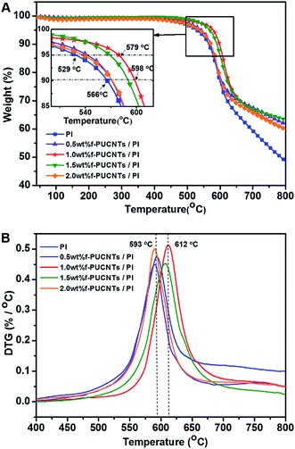 | ||
| Fig. 5 TGA (A) and DTG (B) curves of f-PUCNTs/PI composite fibers with different loadings of f-PUCNTs (0, 0.5, 1.0, 1.5 and 2.0 wt%). | ||
Glass transition temperature (Tg) and the dynamic storage modulus (E′) of f-PUCNTs/PI composite fibers were determined by dynamic mechanical analyses (DMA) as shown in Fig. 6. Both of Tg and E′ (50 °C) show increasing trend with the addition of f-PUCNTs, and the values reach the maximum at a loading of 1.0 wt% f-PUCNTs. Tg and E′ (50 °C) of 1.0 wt% f-PUCNTs/PI composite fiber are 13 °C and 5.36 GPa higher than those of PI fiber, respectively.
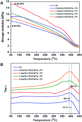 | ||
Fig. 6 Dynamic storage modulus (A) and tan![[thin space (1/6-em)]](https://www.rsc.org/images/entities/char_2009.gif) δ (B) in DMA of f-PUCNTs/PI composite fibers with different loadings of f-PUCNTs (0, 0.5, 1.0, 1.5 and 2.0 wt%). δ (B) in DMA of f-PUCNTs/PI composite fibers with different loadings of f-PUCNTs (0, 0.5, 1.0, 1.5 and 2.0 wt%). | ||
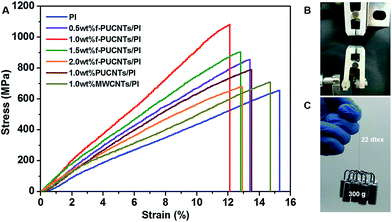
The typical stress–strain curves of the PI-based composite fibers containing MWCNTs, PUCNTs and f-PUCNTs are shown in Fig. 7 and the detailed tensile properties are summarized in Fig. S4.† Both tensile strength and Young's modulus of f-PUCNTs/PI composite fibers are improved markedly with addition of only small amount of f-PUCNTs. Particularly, the strength and modulus of f-PUCNTs/PI fiber at 1.0 wt% f-PUCNTs loading increase from 655 MPa and 4.28 GPa of PI fiber to 1082 MPa and 8.94 GPa, corresponding to increase 165% and 208%, respectively. However, the mechanical properties decrease with more addition of f-PUCNTs, which is referred to that the aggregation of f-PUCNTs weakens the efficient reinforcement instead. The tensile strength and Young's modulus of f-PUCNTs/PI composite fiber also increase to 137% and 153% of those of PUCNTs/PI composite fiber containing the same amount of PUCNTs (1.0 wt%), respectively. The order of strength and modulus is: 1.0 wt% f-PUCNTs/PI fiber > 1.0 wt% PUCNTs/PI fiber > 1.0 wt% MWCNTs/PI fiber > PI fiber. Fig. 7C and a Video in ESI† intuitively show the excellent reinforcement of f-PUCNTs by comparing PI fiber and 1.0 wt% f-PUCNTs/PI fiber with the same linear density.
According to synergistic effect of outer-wall graphene and inner-wall CNTs,24–26,42–44 combining with the analyzing of the fracture surface of f-PUCNTs/PI composite fibers as shown in Fig. 8, the reason for increased mechanical properties can probably be understood more easily. Fracture surface of PI fiber (Fig. 8(a) and (a′)) is almost smooth and only a few stress concentration sites (white dots) exist, representing the fracture is homogeneous scission of PI chains. With addition of 0.5 wt% f-PUCNTs, part of the fracture surface (Fig. 8(b) and (b′)) becomes rough and some pull-out f-PUCNTs could be clearly observed on the rough surface. With 1.0 wt% f-PUCNTs dispersed homogeneously, the fracture surface of 1.0 wt% f-PUCNTs/PI fiber (Fig. 8(c) and (c′)) becomes rougher and more pull-out f-PUCNTs are observed, revealing better effect on improving the mechanical performance. However with 1.5 wt% f-PUCNTs added, aggregated structure of f-PUCNTs can be seen in the fracture surface (Fig. 8(d) and (d′)), which weakens efficient reinforcement instead. The similar changes of roughness for the longitudinal surface of corresponding f-PUCNTs/PI composite fibers can be seen from the longitudinal view of the fibers as shown in Fig. S5.† For f-PUCNTs/PI composite fibers containing certain f-PUCNTs loadings, outer-wall graphene with large contact area and covalent connection with several PI chains show strong interfacial interaction between f-PUCNTs and PI matrix, largely increasing the efficiency of stress transfer from PI matrix to f-PUCNTs.
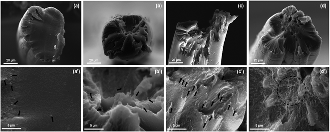 | ||
| Fig. 8 SEM images of fracture surface of f-PUCNTs/PI fibers with different contents of f-PUCNTs (a and a′) 0 wt%, (b and b′) 0.5 wt%, (c and c′) 1.0 wt% and (d and d′) 1.5 wt%. | ||
4. Conclusions
PUCNTs prepared by longitudinal unzipping the MWCNTs contained rich oxygenic groups at outer-wall graphene to provide reaction sites for preparing f-PUCNTs. f-PUCNTs as reinforcements combined the advantages of outer-wall graphene and inner-wall CNTs, and possessed groups to connect covalently with PI, so it was good for strengthening the composite fibers and also for increasing their thermal properties. A series of f-PUCNTs/PI composite fibers with excellent mechanical and thermal properties were prepared by wet spinning and thereafter heat treatment. The tensile strength and Young's modulus of f-PUCNTs/PI composite fiber containing 1.0 wt% f-PUCNTs are 165% and 208% those of PI fiber, respectively, and are 137% and 153% those of the composite fiber containing the same amount of PUCNTs, respectively. Moreover, 5% weight loss temperature and glass transition temperature of 1.0 wt% f-PUCNTs/PI composite fiber were 50 °C and 13 °C higher than those of PI fiber, respectively. This work provided a novel method to prepare high performance nanocomposite fibers and expanded the application of PUCNTs.Acknowledgements
This work was performed with the support of a project funded by the Priority Academic Program Development of Jiangsu Higher Education Institutions, Jiangsu Provincial Natural Science Foundation of China (No. BK20161214) and the State and Local Joint Engineering Laboratory for Novel Functional Polymeric Materials.References
- J. W. Gooch, Polyimide Fiber, Springer, 2011 Search PubMed.
- T. K. T. Agag and T. Takeichi, Polymer, 2001, 42, 3399–3408 CrossRef CAS.
- B. F. Yagoub mansoori, J. Polym. Mater., 2014, 31, 461–478 Search PubMed.
- J. Lee, C.-L. Lee, K. Park and I.-D. Kim, J. Power Sources, 2014, 248, 1211–1217 CrossRef CAS.
- D. Ding, X. Yan, X. Zhang, Q. He, B. Qiu, D. Jiang, H. Wei, J. Guo, A. Umar, L. Sun, Q. Wang, M. A. Khan, D. P. Young, X. Zhang, B. Weeks, T. C. Ho, Z. Guo and S. Wei, Superlattices Microstruct., 2015, 85, 305–320 CrossRef CAS.
- F. Song, Q. Wang and T. Wang, Compos. Sci. Technol., 2016, 134, 251–257 CrossRef CAS.
- T. Ogasawara, Y. Ishida, T. Ishikawa and R. Yokota, Composites, Part A, 2004, 35, 67–74 CrossRef.
- B. Zhu, S. Xie, Z. Xu and Y. Xu, Compos. Sci. Technol., 2006, 66, 548–554 CrossRef CAS.
- Y. Hu, J. Shen, C. Qin, L. Wu, B. Zhang and M. Ye, Polym. Compos., 2009, 30, 374–380 CrossRef CAS.
- C. Yin, J. Dong, Z. Li, Z. Zhang and Q. Zhang, Composites, Part B, 2014, 58, 430–437 CrossRef CAS.
- E. P. Favvas, S. F. Nitodas, A. A. Stefopoulos, S. K. Papageorgiou, K. L. Stefanopoulos and A. C. Mitropoulos, Sep. Purif. Technol., 2014, 122, 262–269 CrossRef CAS.
- S.-M. Yuen, C.-C. M. Ma, Y.-Y. Lin and H.-C. Kuan, Compos. Sci. Technol., 2007, 67, 2564–2573 CrossRef CAS.
- M. Chen, J. Yin, R. Jin, L. Yao, B. Su and Q. Lei, Thin Solid Films, 2015, 584, 232–237 CrossRef CAS.
- O.-K. Park, J.-Y. Hwang, M. Goh, J. H. Lee, B.-C. Ku and N.-H. You, Macromolecules, 2013, 46, 3505–3511 CrossRef CAS.
- L. Cao, Q. Sun, H. Wang, X. Zhang and H. Shi, Composites, Part A, 2015, 68, 140–148 CrossRef CAS.
- S. Zhang, Y. Li, J. Sun, J. Wang, C. Qin and L. Dai, RSC Adv., 2016, 6, 74053–74060 RSC.
- K. S. Novoselov, V. I. Fal'ko, L. Colombo, P. R. Gellert, M. G. Schwab and K. Kim, Nature, 2012, 490, 192–200 CrossRef CAS PubMed.
- L. He, P. Zhang, H. Chen, J. Sun, J. Wang, C. Qin and L. Dai, Polym. Int., 2016, 65, 84–92 CrossRef CAS.
- J. Shen, M. Shi, N. Li, B. Yan, H. Ma, Y. Hu and M. Ye, Nano Res., 2010, 3, 339–349 CrossRef CAS.
- J. Longun, G. Walker and J. O. Iroh, Carbon, 2013, 63, 9–22 CrossRef CAS.
- M. H. Tsai, I. H. Tseng, J. C. Chiang and J. J. Li, ACS Appl. Mater. Interfaces, 2014, 6, 8639–8645 CAS.
- Z. Zheng, Z. Wang, Q. Feng, F. Zhang, Y. Du and C. Wang, Mater. Chem. Phys., 2013, 138, 350–357 CrossRef CAS.
- J. Y. Kim, T. Kim, J. W. Suk, H. Chou, J. H. Jang, J. H. Lee, I. N. Kholmanov, D. Akinwande and R. S. Ruoff, Small, 2014, 10, 3405–3411 CrossRef CAS PubMed.
- S. Chatterjee, F. Nafezarefi, N. H. Tai, L. Schlagenhauf, F. A. Nüesch and B. T. T. Chu, Carbon, 2012, 50, 5380–5386 CrossRef CAS.
- M. Safdari and M. S. Al-Haik, Carbon, 2013, 64, 111–121 CrossRef CAS.
- S. Kumar, L. L. Sun, S. Caceres, B. Li, W. Wood, A. Perugini, R. G. Maguire and W. H. Zhong, Nanotechnology, 2010, 21, 105702 CrossRef CAS PubMed.
- L. Yu, J. S. Park, Y. S. Lim, C. S. Lee, K. Shin, H. J. Moon, C. M. Yang, Y. S. Lee and J. H. Han, Nanotechnology, 2013, 24, 155604 CrossRef PubMed.
- D. V. Kosynkin, A. L. Higginbotham, A. Sinitskii, J. R. Lomeda, A. Dimiev, B. K. Price and J. M. Tour, Nature, 2009, 458, 872–876 CrossRef CAS PubMed.
- D. V. K. Amanda, L. Higginbotham, A. Sinitskii, Z. Sun and J. M. To, ACS Nano, 2010, 4, 2059–2069 CrossRef PubMed.
- H. Hu, M. Feng and H. Zhan, Talanta, 2015, 141, 66–72 CrossRef CAS PubMed.
- Y. Song, M. Feng and H. Zhan, Electrochem. Commun., 2014, 45, 95–98 CrossRef CAS.
- Y. Zhang, Y. Song, Y. Gan, M. Feng and H. Zhan, J. Mater. Chem. C, 2015, 3, 9948–9954 RSC.
- M. Liu, C. Zhang, W. W. Tjiu, Z. Yang, W. Wang and T. Liu, Polymer, 2013, 54, 3124–3130 CrossRef CAS.
- W. Yuan, J. Che and M. B. Chan-Park, Chem. Mater., 2011, 23, 4149–4157 CrossRef CAS.
- T.-C. Huang, L.-C. Yeh, H.-Y. Huang, Z.-Y. Nian, Y.-C. Yeh, Y.-C. Chou, J.-M. Yeh and M.-H. Tsai, Polym. Chem., 2014, 5, 630–637 RSC.
- R. S. Irwin, US Pat., 4640972, 1987.
- G. Mihailov, M. Lebejeva and G. Baklagina Yu, J. Prakt. Chem., 2000, 73, 472 Search PubMed.
- D. Zhang, L. Shi, J. Fang, K. Dai and X. Li, Mater. Chem. Phys., 2006, 97, 415–419 CrossRef CAS.
- P. Samyn, G. Schoukens, F. Verpoort, J. Van Craenenbroeck and P. De Baets, Macromol. Mater. Eng., 2007, 292, 523–556 CrossRef CAS.
- Y. H. Y. Keunok Han Yu, J. M. Rhee, M. H. Lee and S. C. Yu, Bull. Korean Chem. Soc., 2013, 24, 357–362 Search PubMed.
- M. Tanaka and R. J. Young, J. Mater. Sci., 2006, 41, 963–991 CrossRef CAS.
- L. Gong, I. A. Kinloch, R. J. Young, I. Riaz, R. Jalil and K. S. Novoselov, Adv. Mater., 2010, 22, 2694–2697 CrossRef CAS PubMed.
- J. R. Potts, D. R. Dreyer, C. W. Bielawski and R. S. Ruoff, Polymer, 2011, 52, 5–25 CrossRef CAS.
- C. DeValve and R. Pitchumani, Carbon, 2013, 63, 71–83 CrossRef CAS.
Footnote |
| † Electronic supplementary information (ESI) available: Experimental data and characterization details of f-PUCNTs and f-PUCNTs/PI composite fibers. See DOI: 10.1039/c7ra01738c |
| This journal is © The Royal Society of Chemistry 2017 |

