
 Open Access Article
 This Open Access Article is licensed under a
 Creative Commons Attribution 3.0 Unported Licence
Fe-Doped SnO2 catalysts with both BA and LA sites: facile preparation and biomass carbohydrates conversion to methyl lactate MLA†
Xiaoli Zhaoa,
Tao Wena,
Junjie Zhanga,
Jianfeng Yea,
Zhonghua Maa,
Hong Yuanb,
Xiaozhou Ye*a and
Yun Wang *a
*a
aCollege of Science, Huazhong Agricultural University, Wuhan 430070, Hubei, PR China. E-mail: xzye@mail.hzau.edu.cn; Yunwang123@126.com
bCollege of Chemistry, Central China Normal University, Wuhan 430070, Hubei, PR China
First published on 18th April 2017
Abstract
Fe-Doped SnO2 solid acid catalysts with both Lewis acid and Brønsted acid sites were synthesized by a facile sol–gel method comprising hydrolysis of SnCl4 and Fe(NO3)3 under the action of NH4OH in aqueous solution, followed by 500 °C calcination. Characterization of the thus-prepared Fe-doped SnO2 catalysts with HRTEM, XRD, Raman, and XPS demonstrate the insertion of Fe3+ into the SnO2 crystal lattice. Based on the Py-IR, NH3-TPD and BET characterization, the Lewis acid and Brønsted acid sites and acidity of the as-prepared catalysts could be adjusted by controlling the Fe doping amounts and calcination temperature. When evaluated as solid acid catalysts for the conversion of sugar to methyl lactate (MLA), the Fe-doped SnO2 catalyst with a 0.2 Fe/Fe + Sn feed ratio exhibited a preferable MLA yield of 35% under the best conditions. The catalysts also showed good selectivity and reusability. The enhanced catalytic activity could be attributed to the cooperation of Lewis acid and Brønsted acid, and appropriate acid strength. In addition, when the substrates were sucrose and fructose, the yields of MLA reached 44% and 52%.
1 Introduction
Biomass carbohydrates are the most abundant and renewable green resources in nature. The conversion of carbohydrates to various value added chemicals is of great importance to ease the depletion of fossil carbon reserves and environmental pollution.1 Of all the chemicals converted from biomass carbohydrates, lactate acid (LA) and methyl lactate (MLA) are both important platform chemicals, which have been widely used in the industries of food additives, cosmetics, pharmaceuticals, paints and so on.2,3 Therefore, the conversion of biomass into LA and its' derivatives has wide applications and hence attracts more and more interest.Lactic acid was first produced industrially by Monsanto Chemical Company in 1963, by converting acetaldehyde and hydrogen cyanide into lactonitrile, which is further hydrolyzed to lactic acid.4 But this method has several drawbacks, such as poisonous raw materials, serious pollution and high production cost. Currently, lactic acid is produced mainly by the fermentation of sugars.5 But during fermentation, continuous buffering is essential to maintain the pH of the broth, hence resulting in significant amounts of waste. In addition, low volumetric production rate,6 complicate purification and separation, and relatively high costs limit the application of LA.7 Therefore, chemo-catalytic processes attract more and more attentions as a promising alternative to current fermentation procedure.8–12 In this context, the use of homogeneous Lewis acid catalysts to synthesize LA and MLA was propose.13 Several compounds as homogeneous catalysts have been found to be efficient for the conversion of biomass to LA, such as Ca(OH)2, NaOH,3 Ba(OH)2,14 ErCl3,10 Pb2+,15 Zn2+,16 and so on. Besides, Hayashi et al.17 reported the conversion of trioses to LA using tin chlorides. Of all the alkaline Lewis acid catalysts, tin-based Lewis acid exhibits better catalytic activities.18 By using these homogeneous catalysts, the yield of LA and its' derives can reach 30% to 70%. Nevertheless, this is less than ideal since this process requires tedious regeneration, the products are hard to separate, and the starting materials are usually toxic and expensive. In view of these drawbacks, it is important to develop heterogeneous catalytic routes for the production of MLA from biomass. It has a higher rate of reaction and allows the use of more types of biomass feedstocks such as glycerol,19 fructose,20 glucose.21 In 2010, Holm et al.22,23 reported the direct formation of MLA from common sugars catalyzed with Lewis acidic zeotypes, such as Sn-beta. In particular, MLA yield reached 68% when the sucrose was the substrate. In addition, the addition of K2CO3 increased the yield of methyl lactate from sucrose at 170 °C to 75%.12 However, the synthesis of Sn-β catalysts are extreme complicate, environmental unfriendly and time consuming. During the process, hydrofluoric acid was needed to form hardened gel, and the synthesis took place in autoclave with high pressure for 10 to 20 days to achieve high crystallinity. To overcome this drawback, Murillo et al.24 reported a MCM-41 type mesoporous materials containing tin (Si/Sn = 55) with high specific surface area and high pore volume. The yields of MLA converted from glucose was 43%. In addition, Sn-MWW zeolite was synthesized and proved to be highly selective and recyclable catalysts for the trioses conversion.25 Compared to Sn-beta catalysts, synthesis process of Sn-MWW zeolite was simplified, but the ratio of reagents, such as TEOS, CTABr, NaOH and tin precursors are delicate to control. Recently, three dimensionally ordered mesoporous imprinted (3Dom-i) Sn-MFI exhibited improved catalytic performance for the isomerizations of C5 and C6 sugars, by greatly enhanced molecular transport.26 This catalyst was relatively easy to fabricate, but it was only used to converse C3 sugar. Apart from tin based catalysts, Zr–SBA-15 also showed excellent catalytic performance for the conversion of carbohydrates to MLA.27 The yields of MLA reached 41% and 44% from pentose and hexose in the near-critical methanol at 240 °C. In addition, solid base catalysts, such as hydrotalcites,28 MgO,29 alkaline media supported noble metal,30 could also be used to catalyze the conversion of sugar to MLA. Although the fabrication process of such solid base catalysts was comparatively simple, but the yields of MLA were relatively low currently. In general, of all the heterogeneous catalysts, tin-based catalysts exhibit superior catalytic performance for the conversion of carbohydrate to MLA. However, the production of such tin-based catalysts are often complicate, and involved multi-step, time-consuming synthesis process, which may limited their industrial utilization.31 Hence, the development of new tin-based catalysts with simple fabrication process and improved catalytic performance is important for the production and application of MLA.
According to the literature, bifunctional catalysts with both Lewis and Brønsted acid sites exhibit higher efficiency and selectivity for the conversion of sugar to MLA.8,9 For instance, Sels et al.32 designed a carbon–silica bifunctional catalyst with both Lewis acid sites and weak Brønsted acid sites. During the sugar conversion, the weak Brønsted acid sites are demonstrated to be efficient for the formation of pyruvic aldehyde (PAL) from glyceraldehyde (GLY). After that, PAL is further converted into MLA by the catalysis of Lewis acid. Therefore, the presence of weak Brønsted acid sites accelerated the sugar conversion, and nanoscale metal catalysts are effective in catalyzing the biomass into the desired platform compounds.33 Herein, a novel Fe-doped SnO2 solid acid catalysts with both Lewis and Brønsted acid sites was synthesized by simple sol–gel process. By doping Fe ions into SnO2 lattice, the specific surface area evidently increased, and the Lewis and Brønsted acid sites are evidently enriched. The acid strength and acid sites could be adjusted by controlling the Fe doping amount and other reaction conditions. For the conversion of glucose to MLA, Fe-doped SnO2 catalysts exhibit favorable catalytic performance, and the MLA yield reaches 35% under optimized condition. The as-prepared catalysts also exhibits good selectivity and reusability. In addition, when the substrate is fructose, the MLA yield reaches 52%.
2 Experimental
2.1 Synthesis of SnO2, Fe-doped SnO2 and Fe2O3 catalysts
In a typical synthesis for Fe-doped SnO2 catalysts, 0.5 mol L−1 SnCl4 solution and 0.5 mol L−1 Fe(NO3)3 solution were mixed under constant stirring. The mole ratio of Fe/(Fe + Sn) are 0, 0.1, 0.2 and 0.3, 1, respectively. Then 7.2 mol L−1 NH4OH solution were added dropwisely under constant stirring until the pH value of the mixed solution reached 9.5. After the reaction, the precipitate was collected by centrifugation, washed several times with water, dried at 100 °C for 6 hours, and calcined at 500 °C for 3 hours with the heating rate of 1 °C min−1.2.2 Material characterization
The morphology and microstructure of the prepared catalysts were characterized by transmission electron microscopy (TEM, Tecnai G2 F20 S-TWIN), selected area electron diffraction (SAED), and elemental mapping. X-ray powder diffraction (XRD) patterns were recorded on a Bruker D8 Advanced diffactometer using CuKα radiation at a scanning rate of 10 °C min−1. X-ray photoelectron spectroscopy (XPS) experiments were performed on a VG Multilab-2000 with Al Kα (300 W) radiation. Energy scale and binding energy were calibrated with amorphous C at the binding energies of C 1s (284.6 eV). Raman measurements were performed on inVia Raman spectrometer (Renishaw, UK) equipped with a co-focusing microscope (Leica, German). The sample were excited under a He–Ne laser (633 nm) with laser power of 10 mW. Nitrogen adsorption was measured using ASAP 2460 volumetric adsorption apparatus (Micromeritics). The surface areas and pore size distribution were calculated by means of the BET equation. Analysis of Lewis and Brønsted acid acidity was measured by pyridine probe spectroscopy (Py-IR). Temperature-programmed desorption (NH3-TPD) measurement (PCA-1200), 0.1 g sample was heated at 400 °C for 2 h under helium flow of 30 cm3 min−1, then cooled to 100 °C and adsorpted ammonia in a flow with NH3/He (30 cm3 min−1, 15%) for 30 min. Physically adsorbed ammonia was removed by He for 30 min. Then the sample was heated to 800 °C at 10 °C min−1 while monitoring the desorption of ammonia. Temperature-programmed desorption mass spectrum (NH3-TPD-MS) measurement: (Auto Chem II 2920), approximately 100 mg of sample was placed in a U-shaped quartz tube and heated from room temperature to 400 °C at 10 °C min−1. Dry pretreatment, He gas flow (50 mL min−1) for 2 h, then cooled to 50 °C, into NH3/He (50 mL min−1) mixture for 1 h to saturation, switching He gas flow (50 mL min−1) for 1 h to remove the surface of the weak physical adsorption of NH3. The sample was heated to 800 °C at a heating rate of 10 °C min−1 in He gas stream (50 mL min−1). The effluent gas was detected by TCD and mass spectrometer (Mz = 17, NH3, Mz = 18, H2O).2.3 Catalytic tests and products analysis
Catalytic test were performed in stainless steel micro-reactors of 50 mL. In a typical test, 0.22 g substrate, 0.015 g naphthalene (internal standard), and 0.16 g catalysts were added into 20 mL absolute methanol. The reaction was then taken place at 160 °C under 1 MPa for 20 h. After the reaction, the liquid solution were collected by centrifugation. The undiluted reaction mixture was analysed on a GC (Agilent 7820A instrument) equipped with an HP-5 capillary column (30.0 m × 320 μm × 0.25 μm) and an FID detector. The reaction mixture was also analysed on an Agilent 1200 series HPLC with a RID detector. An Agilent 6850 GC system coupled with an Agilent 5975C mass detector was used for qualitative analysis. The yields of MLA, PADA were calculated from the GC-data, based on the internal standard.For the recycling tests, after each reaction, the liquid solution was examined by GC analysis. The residual catalyst powder was collected by centrifugation, washed several times with absolute methanol, dried at 100 °C. Then fresh reaction components were added to start the next reaction cycle.
The substrate conversion (mol%) and the product yield (mol%) were calculated based on carbon balance:

K: when substrate was glucose or fructose, K equals to 2; when substrate was sucrose, K equals to 4.
3 Results and discussion
3.1 Catalyst preparation and characterization
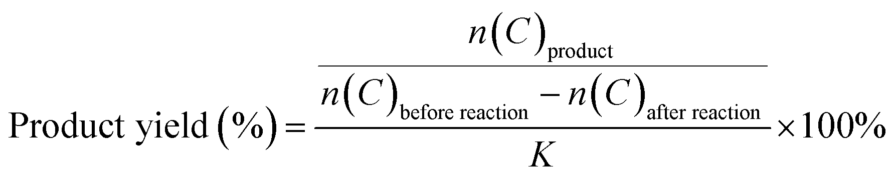
The Fe-doped SnO2 catalysts were obtained by simple sol–gel process. First, SnCl4 and Fe(NO3)3 solution were mixed under magnetic stirring with certain Fe/Fe + Sn mole ratio. Then NH4OH solution were dropwisely added to the solution. After certain reaction time, the precipitate was collected, washed, dried and sintered at 500 °C for 3 hours with the heating rate of 1 °C min−1. We denoted as-prepared Fe-doped SnO2 catalysts as 0.1FS, 0.2FS, and 0.3FS when the Fe/Fe + Sn mole ratio was 0.1, 0.2 and 0.3, respectively. The TEM images and SAED patterns of 0.2FS annealed at 500 °C are shown in Fig. 1. As shown in Fig. 1a, the 0.2FS catalyst is composed of nanocrystals with the size of roughly 5 nm. Fig. 1b shows the HRTEM image of the sample. The clear lattice fringes indicated the good crystallinity of sample, and the lattice spacing of 0.27 nm corresponded to the (101) planes of tetragonal SnO2. In addition, the selected area electron diffraction (SAED) pattern (Fig. 1b inset) further confirmed the crystal structure of polycrystalline tetragonal SnO2. The elemental mapping images of 0.2FS catalyst (Fig. 1c–f) reveals the homogeneous spatial distribution of Fe elements in the SnO2 crystals, implying that the Fe atoms are evenly inserted into SnO2 lattices.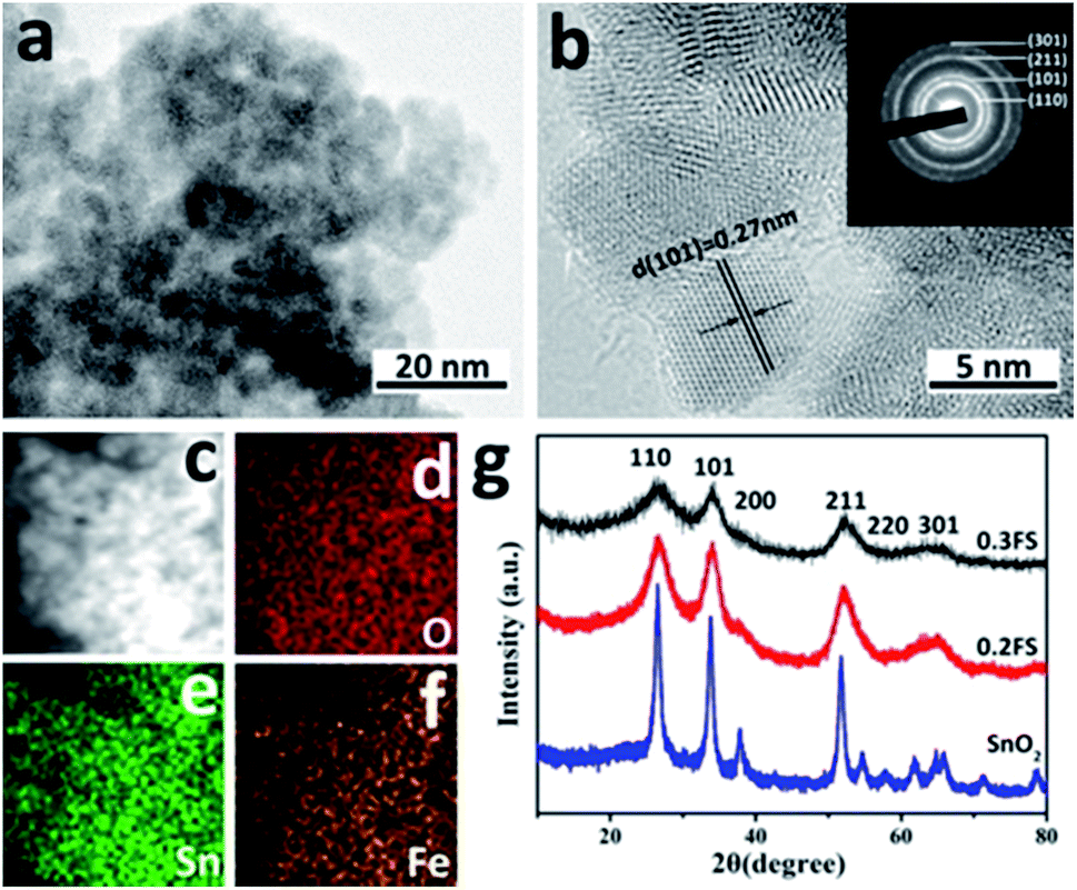 | ||
| Fig. 1 TEM (a) and high resolution TEM (HRTEM) (b) images of 0.2FS catalyst, inset image is the selected area electron diffraction (SAED) pattern; STEM image of 0.2FS catalyst (c) and EDX mapping images of O (d), Sn (e), Fe (f); (g) XRD X-ray diffraction patterns of Fe-doped SnO2 catalysts with different Fe-doped amounts. | ||
The crystal structure and the possible phase change of the undoped and Fe-doped SnO2 samples were examined by X-ray diffraction. As shown in Fig. 1g, the crystal structure of these four samples are all tetragonal SnO2 (JCPDS no. 41-1445), as confirmed by the appearance of diffraction peaks of (110), (101), (200), (211), (220) and (301), and there are no exsistance of diffraction peaks of Fe2O3. As the Fe-doped into SnO2 crystals, all the diffraction peaks of Fe-doped SnO2 samples exhibited slight shifts to higher 2θ values, it is calculated that for the diffraction peaks of (110) of 0.2FS sample, the 2θ values shifts to higher value for 0.26 degrees, compared with pure SnO2, as the Fe doped into SnO2 samples (Fig. S1†), which was attributed to the decreased lattice spacings due to the replacement of smaller Fe3+ (0.645 Å) ions of Sn4+ (0.72 Å).34,35 In addition, to further confirm that the Fe ion was doped into SnO2 lattice, instead of forming Fe2O3/SnO2 composite, we also made three reference sample, pure Fe2O3, Fe2O3/SnO2, and Fe2O3 mixed with SnO2 with the molar ratio of Fe/(Fe + Sn) of 20%, the details of fabricating these reference samples were presented in Experimental section. The X-ray diffraction spectrum of these samples were shown in Fig. S2,† The results showed that for the samples of Fe2O3/SnO2, Fe2O3 mixed with SnO2, the diffraction peaks are almost the same, and corresponding to SnO2 tetragonal phase (JCPDS no. 41-1445) and Fe2O3 hematite phase (JCPDS no. 33-0664). Therefore, XRD results shows that for our Fe-doped SnO2 sample, it is more likely that Fe doping into SnO2 lattice, instead of forming Fe2O3/SnO2 composite. On the other hand, it's worth mentioning that with increasing Fe-doped levels, the intensities of the diffraction peaks decreased and the full-width at half-maximum (FWHM) increased, which indicated that the Fe incorporation into SnO2 lattice led to a decrease of crystalline domain size.36,37 Furthermore, we also investigated the Raman spectrum of undoped SnO2 and 0.2FS catalyst, as shown in Fig. S3.† The peaks located at about 482, 641, and 752 cm−1 for both samples corresponded to Eg, A1g and B2g vibration modes of tetragonal SnO2, respectively. In addition, these Raman peaks of Fe-doped SnO2 showed a slight shift compared with those of undoped SnO2, indicating the doping of Fe ion into SnO2.38,39 The XRD and Raman results of as-prepared Fe-doped SnO2 catalysts indicate that Fe atoms have been successfully doped into the SnO2 lattice, and the doping amounts can be well controlled by adjusting synthesis condition.
The X-ray photoelectron survey spectrum (XPS) was used to investigate the surface composition and elements oxidation states of 0.2FS catalyst. As shown in Fig. 2a and b, the binding energies at 486.7 eV, 495.1 eV, and 716.3 eV arised from Sn 3d5/2, Sn 3d3/2, and Sn 3p3/2 of SnO2,40 respectively. In Fig. 2b, the Fe 2p3/2 and Fe 2p1/2 line of the sample were found at a binding energy of 711.0 eV and 725.0 eV, respectively,34 which was consistent with typical values observed for Fe3+, indicating the presence of Fe in the doped SnO2 system. Moreover, the Fe 3p band at 56 eV was also observed, as shown in Fig. 2c. In Fig. 2d, the binding energy of O 1s was 530.4 eV, which can be attributed to Sn–O–Sn mode of SnO2. Moreover, an additional shoulder peak at 513.4 eV was also observed, which could be ascribed to the Sn–O–Fe coordination.41,42
 | ||
| Fig. 2 High-resolution XPS spectra of 0.2FS sample. (a) Sn 3d, (b) Sn 3p and Fe 2p, (c) Fe 3p, (d) O 1s. | ||
Fig. S4 and S5† shows the N2 adsorption–desorption isotherms and BJH (Barrett–Joyner–Halenda) pore size distribution curves of undoped SnO, Fe2O3, Fe2O3/SnO2, Fe2O3 mixed SnO2 and Fe doped SnO2 catalysts, they all exhibits a type-IV isotherm.32 As shown in Table 1, with doping Fe into SnO2 catalysts, the surface areas evidently increased; and as the Fe doping amounts increased, the specific surface areas of Fe-doped SnO2 increased from 65 to 98 m2 g−1, while the average pore diameter slightly decreased from 3 nm to 2 nm, respectively. The observed increasement in specific surface area might be due to the reduced particle sizes caused by Fe doping.
| Catalyst | SBET (m2 g−1) | Mean (nm) | Glucose conversion (%) | MLA yield (%) | PADA yield (%) | Acidic sites distribution based on NH3-TPD data (mL g−1) | ||
|---|---|---|---|---|---|---|---|---|
| Weak T < 200 °C | Medium 200 °C < T < 400 °C | Strong T > 400 °C | ||||||
| Blank | — | — | 95 | 10 | 11 | |||
| SnO2 | 28 | 4 | 87 | 3 | 3 | — | — | 7.67 |
| Fe2O3 | 25 | 12 | 93 | 4 | 2 | 0.307 | — | 0.584 |
| Fe2O3/SnO2 | 28 | 13 | 91 | 5 | 3 | 0.220 | — | 0.368 |
| Fe2O3 mixed SnO2 | 32 | 13 | 86 | 3 | 3 | 0.126 | — | 1.103 |
| 0.1FS | 65 | 2 | 93 | 10 | 5 | — | — | 15.51 |
| 0.2FS | 83 | 2 | 98 | 35 | 7 | — | 19.24 | — |
| 0.3FS | 98 | 2 | 96 | 31 | 6 | — | 17.02 | — |
3.2 Catalytic properties of Fe-doped SnO2 catalysts with different Fe-doped amounts
In order to test the catalytic performance of SnO2 catalysts with different Fe doped amounts, the MLA yields for the reactions of glucose in methanol at 160 °C for 20 h were tested and the results were listed in Table 1. The yield of MLA was 10% for the reaction without catalyst, which might be caused by the catalytic reaction of subcritical methanol.29 Pure SnO2 and pure Fe2O3 both exhibited little catalytic activity, which only yielded 3% and 4% MLA, respectively.With the 0.1FS catalyst, the MLA yield increased to 10%. When the Fe doped amounts increased, the catalytic activity was largely promoted, and the glucose conversion and MLA yield catalyzed by 0.2FS reached 99% and 35%, respectively. However, if the Fe doped amounts further increased, for the 0.3FS catalyst, the MLA yield slightly dropped 31%, respectively. Hence, the catalytic performance of SnO2 could be largely enhanced by Fe doping, and were closely related to the Fe-doped amounts. In addition, it is worth mentioning that the as-prepared catalysts have preferable selectivity, the only detectable byproduct was pyruvic aldehyde dialkyl acetal (PADA), and its yields were relatively low, as shown in Table 1. To further confirm that Fe-doped SnO2 could improve the MLA yield, instead of the composition of Fe2O3 and SnO2, we also investigate the catalytic performance of Fe2O3 mixed SnO2 sample and Fe2O3/SnO2 composite. The molar ratio of Fe/(Fe + Sn) of both sample were 20%, which is in accordance with the feeding ratio of 0.2FS. As a result, the MLA yields catalyzed by both sample were only 5% and 3%, respectively. These results confirmed that the composition of Fe2O3 and SnO2 could not improve the MLA yield effectively.
In order to understand the different catalytic behaviors among the Fe-doped SnO2 catalysts, the structure and acidity of different catalysts were characterized. Fig. 3a shows the IR spectra after pyridine chemisorption of undoped and Fe-doped SnO2 catalysts.
 | ||
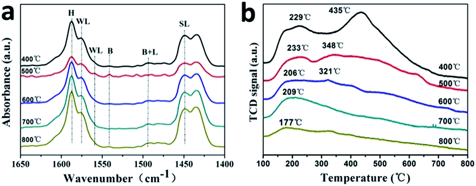
| Fig. 3 The Py-IR images (a) and NH3-TPD profiles (b) of SnO2 catalysts with different Fe-doped amounts. | ||
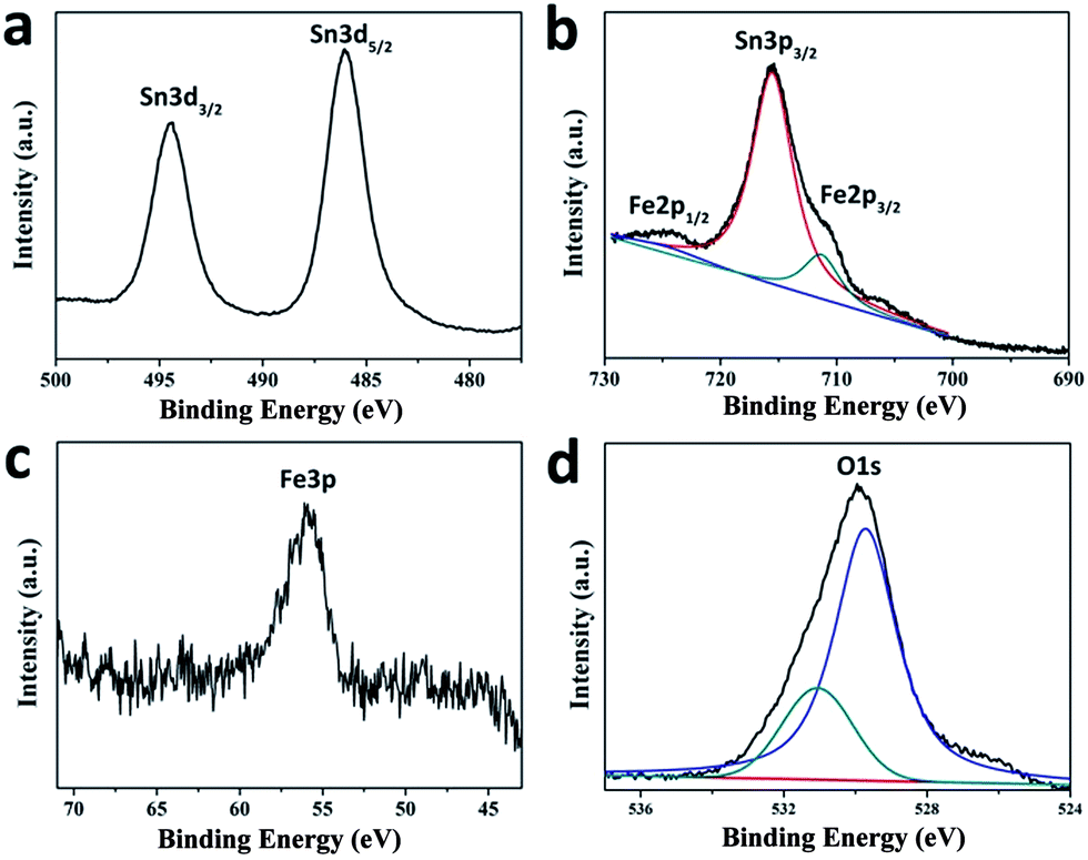
The absorption peaks at about 1618 cm−1 and 1445 cm−1 corresponded to strong Lewis acid sites (denoted with SL); and the peaks at about 1578 cm−1 and 1560 cm−1 corresponded to weak Lewis acid sites (denoted with WL).18 In addition, bands corresponding to the vibration of pyridine adsorption on Brønsted acid sites corresponded to the mixing of Lewis acid sites and Brønsted acid sites.32 The peak located at 1596 cm−1 (denoted with H) is attributed to the hydrogen bond interaction between pyridine and the surface of the catalyst.
Therefore, as-prepared Fe-doped SnO2 catalysts have both Lewis and Brønsted acid sites. We deduct that Lewis acid sites are located in the coordinately unsaturated cations, while Brønsted acidity are generated from surface hydroxyl groups. As shown in Fig. 3a and S7a,† the undoped SnO2, Fe2O3/SnO2 and Fe2O3 mixed SnO2 catalysts revealed very weak acidity for both Lewis acid and Brønsted acid, and pure Fe2O3 only showed a strong Lewis acid site (as shown in Fig. S7a†). On the other hand, for both Lewis and Brønsted acid, with Fe3+ ion doped into SnO2 sample, the acid strength were largely enhanced, and became the strongest with 0.2FS sample. In addition, 0.2FS sample exhibits stronger Brønsted acid strength than other samples, as calculated from the Py-IR characterization (Table S1†) the Lewis acid and Brønsted acid contents of 0.2FS catalyst are relatively higher. According to the literature, Lewis acid for the transformation of glucose plays a vital role,43 weak Brønsted acid sites is crucial in accelerating the rate-determining (dehydration) reaction. Composite catalysts with well-balanced Lewis/Brønsted acidity are able to convert the trioses.32 Hence, we may deduct that the better catalytic performance of 0.2FS sample may due tor the synergistic effect of Lewis acid and Brønsted acid.
To further investigate the acid properties of the Fe-doped SnO2 catalysts, the NH3-TPD profiles of as-prepared catalysts with different Fe-doped amounts were measured (Fig. 3b), and the strength and amount of acid sites were shown in Table 1. According to NH3 desorption peaks over the range of below 200 °C, 200 °C to 400 °C, and above 400 °C, the acid strength were classified as weak, medium and strong, respectively.
As shown in Fig. 3b, pure SnO2 have a desorption peak at 494 °C, which is produced by the condensation of hydroxyl groups,44 as confirmed by the NH3-TPD-MS characterization (Fig. S8†). Since there are fewer hydroxyl group on the surface of as-prepared SnO2, there are no desorption peaks of weak acid sites. Among the other reference samples, Fe2O3 mixed SnO2 has a desorption peak at 474 °C. According to SnO2 NH3-TPD-MS, we speculate that this peak is produced by condensation of hydroxyl groups. Fe2O3 and Fe2O3/SnO2 also had no obvious acidity and low acid content (Fig. S7b†). These results further confirmed that these undoped sample exhibit little acidity. On the other hand, for the samples of Fe doped SnO2 catalysts, 0.1FS sample exhibited a high temperature desorption peak at around 491 °C, which corresponded to strong acid sites present on the catalysts, total Lewis acid amounts were 15.51. When the Fe doping amount increased, the desorption peak moved to lower temperature, which was considered as medium acid sites on the catalysts. Especially, 0.2FS catalyst exhibited two medium acid sites (233 °C and 348 °C), and its total Lewis acid amounts reached 19.24. Associating with the results of Py-IR (Fig. S6†) and catalytic activity, it seems that the coordination of Lewis acid and Brønsted acid, along with the medium acid sites on the Fe-doped SnO2 catalysts surface are advantageous to the conversion of glucose to methyl lactate.27
3.3 Effect of calcination temperature on the catalytic properties of Fe-doped SnO2
The calcination temperature of Fe-doped SnO2 catalysts may have great influence on crystallinity and the nature of acid sites, hence affect catalytic activity. Table 2 lists the catalytic activity for the conversion of glucose to MLA catalyzed by the 0.2FS catalysts with different calcination temperatures. As the calcination temperature raised from 400 °C to 500 °C, the yield of MLA increased from 25% to 35%, then as the temperature continued to raise to 800 °C, the MLA yield gradually decreased to 26%. The yields of byproduct PADA are relative low for all the calcination temperature. To comprehend the influence of calcination temperature, we characterized and analyzed the physical structures and acid properties of 0.2FS catalyst calcined at different temperature.| Calcination temperature | SBET (m2 g−1) | Mean (nm) | Glucose conversion (%) | MLA yield (%) | PADA yield (%) | Acidic sites distribution based on NH3-TPD data (mL g−1) | ||
|---|---|---|---|---|---|---|---|---|
| Weak T < 200 °C | Medium 200 °C < T < 400 °C | Strong T > 400 °C | ||||||
| 400 °C | 88 | 3 | 99 | 25 | 13 | — | 9.49 | 19.42 |
| 500 °C | 83 | 6 | 99 | 35 | 7 | — | 19.24 | — |
| 600 °C | 20 | 11 | 99 | 27 | 7 | — | 9.93 | — |
| 700 °C | 14 | 15 | 99 | 27 | 5 | — | 8.35 | — |
| 800 °C | 7 | 38 | 99 | 26 | 6 | 2.41 | — | — |
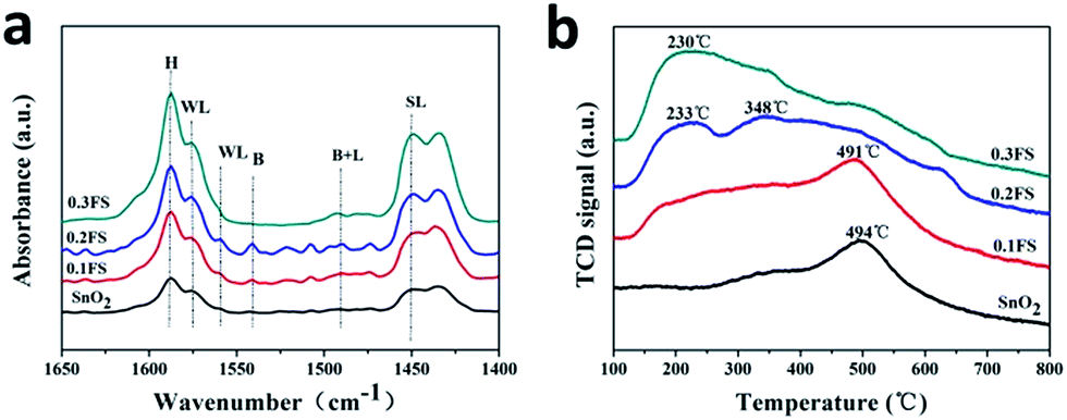
The XRD patterns of 0.2FS catalysts with different calcination temperature are shown in Fig. S9.† All the peaks could be attributed to tetragonal phase SnO2. As the calcination temperature raised from 400 °C to 800 °C, the diffraction peak position did not shift, which indicated that high temperature calcination did not affect Fe doped amounts and crystal structure. In addition, higher calcination temperature resulted in sharper diffraction peak, which indicated increased crystallinity and crystal size of as-prepared catalysts. This result was in accordance with the BET isotherms in Fig. S10.† As listed in Table 2, higher calcination temperature resulted in larger crystal size and hence reduced specific surface area. Fig. 4a shows the IR spectra after pyridine chemisorption of Fe doped SnO2 catalysts calcined at different temperature, and the calculated Lewis acid and Brønsted acid contents were listed in Table S2.† The acid sites and types did not change with raised calcination temperature, which was in accordance with unchanged crystal structure. When the calcination temperatures were 500 °C and 600 °C, the catalysts' acid strength were the strongest, this might due to their preferable crystallinity and specific surface area. Furthermore, the Brønsted acid contents of 500 °C calcinated sample was the highest. Hence the higher MLA yield of 500 °C calcinated sample may be related to the synergistic catalysis of Brønsted acid and Lewis acid. The influence of calcination temperature on catalysts' acid properties were further characterized by NH3-TPD, and the profile was shown in Fig. 4b, while the strength and amount of acid sites were listed in Table 2. As the calcination temperature raised, the NH3 adsorption capacity gradually decreased, which may due to the reduced specific surface area. In addition, when the calcination temperature increased, the NH3 desorption peaks shifted to lower temperature. In particular, when the calcination temperature was 500 °C, the catalysts exhibited two peaks around 233 °C and 348 °C, indicating the medium acid sites presented on the surface of this sample. Combining the catalytic activity data, it implies that medium acid sites are more active for converting glucose to MLA.
 | ||
| Fig. 4 Py-IR patterns (a) and deconvoluted NH3-TPD profiles (b) of 0.2FS with different calcination temperature. | ||
3.4 The effect of catalytic parameters and reusability
In order to explore the effect of catalytic parameters on MLA yield, we performed catalyst reactions with different conditions as shown in Fig. 5a, the reaction temperature plays an important role on the glucose conversion. As the temperature raised from 100 °C to 200 °C, the yield of MLA increased at first, and reached a maximum of 31% at 160 °C. When the temperature continued to raise to 200 °C, the yield of both MLA decreased. This might due to the decomposition of MLA at high temperature. Fig. 5b showed the effect of catalyst amounts. When the catalyst amounts was 0.16 g, the MLA yield reaches 33% and the yield of byproduct PADA was the lowest. Continuing adding catalysts to 0.20 g did not promoted MLA yield, so we use 0.16 g catalysts as our best condition in this research. As shown in Fig. 5c, as the reaction time extended, the yields of MLA and PADA both gradually increased. After 20 hours reaction, the MLA yield remained the maximum of 32%. We also investigated the effect of absolute methanol amount on glucose conversion. As shown in Fig. 5d, when the absolute methanol volume was 20 mL, the yield of MLA reaches 31%. So 20 mL absolute methanol as solvent was the best condition during the catalytic reaction.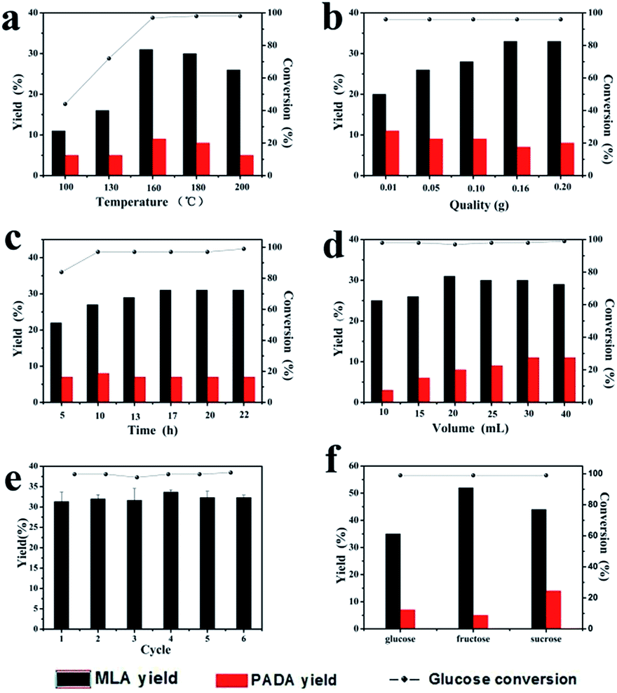 | ||
| Fig. 5 (a–d) The effect of different reaction parameters on the catalytic performance of 0.2FS catalysts for the conversion of glucose to MLA; (a) the effect of reaction temperature, (b) the effect of glucose amounts, (c) the effect of reaction time, (d) the effect of solvent volume. (e) The reusability of 0.2FS catalysts for the conversion of glucose. (f) MLA yields converted from different substrates. | ||
To study the stability of as-prepared 0.2FS catalysts, we performed recycling experiments, as shown in Fig. 5e. After 6 recycles, the MLA yields and glucose conversion remained unchanged, which showed preferable stability of catalytic activity of catalysts. The XRD spectrum and Py-IR spectra of the 0.2FS before and after 6 cycles of reaction was shown in Fig. S11 and S12,† respectively. As a result, the crystal phase and acidity of catalysts did not change after reaction, confirming the good reusability of as-prepared Fe-doped SnO2 catalysts.
3.5 Elucidation of the reaction mechanism
Fig. 5f exhibits the MLA yields converted from different substrates under standard condition. When the substrate was fructose, the MLA yield reached 52%, which was higher than glucose and sucrose. To analyze the catalytic results of different substrates, based on recent researches,17,27,32,43 the reaction of disaccharide converting to MLA occurred in four main steps (Scheme 1). First, sucrose hydrolyzed into glucose and fructose. With the catalysis of Lewis acid,45 the aldose–ketose isomerization occurred, and the glucose isomerized to fructose by the transfer of hydrogen from C-2 to C-1 and from O-2 to O-1.46 Secondly, fructose retro-aldoled to the corresponding trioses, glyceraldehyde (GLY). Thirdly, GLY, in equilibrium with dihydroxyacetone (DHA), underwent dehydration and rearrangement into pyruvic aldehyde (PAL). This reaction was catalyzed by both Lewis acid sites and Brønsted acid sites. With the presence of alcoholic solvents and Lewis acid catalytic sites, PAL was further converted into the desired methyl lactate (A). The presence of too strong Brønsted acid sites should be avoided because they catalyzed the formation of byproduct (PADA) in a parallel reaction path (B).43 From Py-IR and NH3-TPD experiment, it was learned that as-prepared Fe-doped SnO2 catalyst had rich Lewis acid and Brønsted acid catalytic sites. Since the Fe-doped SnO2 catalyst mainly presented medium-strong acid sites, the yield of only detectable byproduct PADA was less than 7%, which indicated preferable selectivity. Based on this reaction mechanism, we deducted that the reaction rate of glucose isomerization was relatively slow with our catalysts,47 hence the MLA yield was the highest when fructose was substrate.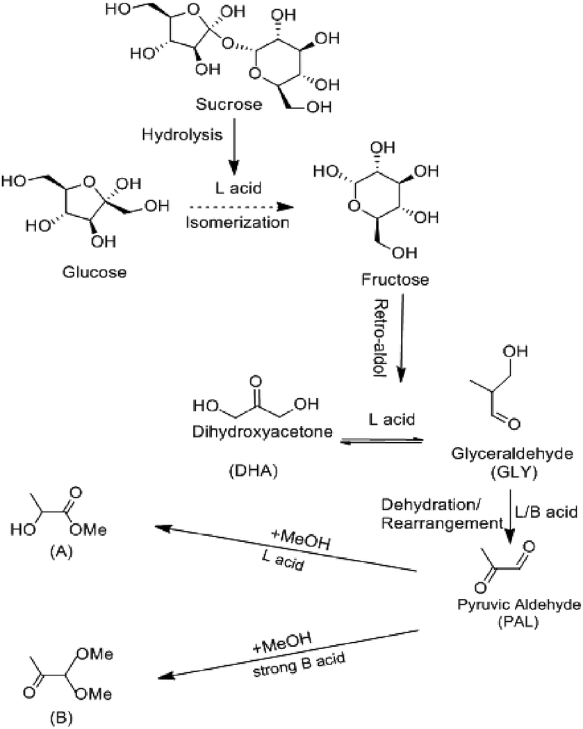 | ||
| Scheme 1 Proposed reaction scheme for converting saccharides into methyl lactate in absolute methanol. The side-reaction leading to the formation of pyruvic aldehyde dialkyl acetal (PADA). | ||
4 Conclusion
We reported a facile preparation of Fe-doped SnO2 catalysts with both Lewis and Brønsted acid sites by sol–gel process. By replacing Sn ion with Fe3+, Fe3+ was inserted into SnO2 crystal lattice, hence produced more BA and LA sites. The Lewis acid sites are located in the coordinative unsaturated cations, while the Brønsted acid sites are generated from surface hydroxyl groups. By changing synthesis condition, the acid property of Fe-doped SnO2 catalysts, such as acid sites distribution and acid strength can be controllably adjusted. In particular, Fe-doped SnO2 catalyst with 0.2 Fe/Fe + Sn feed ratio exhibits best catalytic properties, because of appropriate acid strength and acid type. In the best condition, the yield of MLA converted from glucose reached 35% with this catalyst. In addition, when the substrate was fructose, the yield of MLA was increased to 52%, which indicated profound selectivity under this condition. This research exhibits the facile production of novel catalysts with preferable catalytic performance, which is important for promoting high value application and green transfer of biomass carbohydrates, and have great potential in various applications.Acknowledgements
This work was financially supported by the Fundamental Research Funds for the Central Universities (Grant No. 2662015QC043, 2014PY051), the National Natural Science Foundation of China (Grant No. 21503085), and the Natural Science Foundation of Hubei Province (Grant No. 2015CFB233).Notes and references
- J. Song, H. Fan, J. Ma and B. Han, Green Chem., 2013, 15, 2619 RSC
.
- M. Dusselier, P. Van Wouwe, A. Dewaele, E. Makshina and B. F. Sels, Energy Environ. Sci., 2013, 6, 1415 CAS
- F. Jin and H. Enomoto, Energy Environ. Sci., 2011, 4, 382–397 CAS
- A. N. Vaidya, R. A. Pandey, S. Mudliar, M. S. Kumar, T. Chakrabarti and S. Devotta, Crit. Rev. Environ. Sci. Technol., 2005, 35, 429–467 CrossRef CAS
- A. Corma, S. Iborra and A. Velty, Chem. Rev., 2007, 107, 2411–2502 CrossRef CAS PubMed
- W. Deng, Y. Wang and N. Yan, Curr. Opin. Green Sustainable Chem., 2016, 2, 54–58 CrossRef
- M. Renz, T. Blasco, A. Corma, V. Fornes, R. Jensen and L. Nemeth, Chem.–Eur. J., 2002, 8, 4708–4717 CrossRef CAS
- S. M. Coman, M. Verziu, A. Tirsoaga, B. Jurca, C. Teodorescu, V. Kuncser, V. I. Parvulescu, G. Scholz and E. Kemnitz, ACS Catal., 2015, 5, 3013–3026 CrossRef CAS
- F.-F. Wang, J. Liu, H. Li, C.-L. Liu, R.-Z. Yang and W.-S. Dong, Green Chem., 2015, 17, 2455–2463 RSC
- X. Lei, F.-F. Wang, C.-L. Liu, R.-Z. Yang and W.-S. Dong, Appl. Catal., A, 2014, 482, 78–83 CrossRef CAS
- P. Lakshmanan, P. P. Upare, N.-T. Le, Y. K. Hwang, D. W. Hwang, U. H. Lee, H. R. Kim and J.-S. Chang, Appl. Catal., A, 2013, 468, 260–268 CrossRef CAS
- S. Tolborg, I. Sadaba, C. M. Osmundsen, P. Fristrup, M. S. Holm and E. Taarning, ChemSusChem, 2015, 8, 613–617 CrossRef CAS PubMed
- P. J. Deuss, K. Barta and J. G. de Vries, Catal. Sci. Technol., 2014, 4, 1174 CAS
- D. Esposito and M. Antonietti, ChemSusChem, 2013, 6, 989–992 CrossRef CAS PubMed
- Y. Wang, W. Deng, B. Wang, Q. Zhang, X. Wan, Z. Tang, Y. Wang, C. Zhu, Z. Cao, G. Wang and H. Wan, Nat. Commun., 2013, 4, 2141 Search PubMed
- M. Bicker, S. Endres, L. Ott and H. Vogel, J. Mol. Catal. A: Chem., 2005, 239, 151–157 CrossRef CAS
- Y. Hayashi and Y. Sasaki, Chem. Commun., 2005, 21, 2716–2718 RSC
- C.-C. Chang, Z. Wang, P. Dornath, H. Je Cho and W. Fan, RSC Adv., 2012, 2, 10475 RSC
- S. Ren, X. P. Ye and P. D. Ayers, RSC Adv., 2015, 5, 53230–53239 RSC
- J. Barros dos Santos, N. José Araújo de Albuquerque, C. Lúcia de Paiva e Silva Zanta, M. Roberto Meneghetti and S. Margareti Plentz Meneghetti, RSC Adv., 2015, 5, 90952–90959 RSC
- S. Huang, K.-L. Yang, X.-F. Liu, H. Pan, H. Zhang and S. Yang, RSC Adv., 2017, 7, 5621–5627 RSC
- M. S. Holm, S. Saravanamurugan and E. Taarning, Science, 2010, 328, 602–605 CrossRef CAS PubMed
- M. S. Holm, Y. J. Pagán-Torres, S. Saravanamurugan, A. Riisager, J. A. Dumesic and E. Taarning, Green Chem., 2012, 14, 702 RSC
- B. Murillo, A. Sanchez, V. Sebastian, C. Casado-Coterillo, O. de la Iglesia, M. P. Lopez-Ram-de-Viu, C. Tellez and J. Coronas, J. Chem. Technol. Biotechnol., 2014, 89, 1344–1350 CrossRef CAS
- Q. Guo, F. T. Fan, E. A. Pidko, W. N. P. van der Graaff, Z. C. Feng, C. Li and E. J. M. Hensen, ChemSusChem, 2013, 6, 1352–1356 CrossRef CAS PubMed
- H. J. Cho, P. Dornath and W. Fan, ACS Catal., 2014, 4, 2029–2037 CrossRef CAS
- L. Yang, X. Yang, E. Tian, V. Vattipalli, W. Fan and H. Lin, J. Catal., 2016, 333, 207–216 CrossRef CAS
- A. Onda, T. Ochi, K. Kajiyoshi and K. Yanagisawa, Catal. Commun., 2008, 9, 1050–1053 CrossRef CAS
- Z. Liu, W. Li, C. Pan, P. Chen, H. Lou and X. Zheng, Catal. Commun., 2011, 15, 82–87 CrossRef CAS
- A. Onda, T. Ochi, K. Kajiyoshi and K. Yanagisawa, Appl. Catal., A, 2008, 343, 49–54 CrossRef CAS
- P. Y. Dapsens, C. Mondelli and J. Perez-Ramirez, ChemSusChem, 2013, 6, 831–839 CrossRef CAS PubMed
- F. de Clippel, M. Dusselier, R. Van Rompaey, P. Vanelderen, J. Dijkmans, E. Makshina, L. Giebeler, S. Oswald, G. V. Baron, J. F. Denayer, P. P. Pescarmona, P. A. Jacobs and B. F. Sels, J. Am. Chem. Soc., 2012, 134, 10089–10101 CrossRef CAS PubMed
- Y. Wang, S. De and N. Yan, Chem. Commun., 2016, 52, 6210–6224 RSC
- S. Rani, S. C. Roy, N. Karar and M. C. Bhatnagar, Solid State Commun., 2007, 141, 214–218 CrossRef CAS
- A. Singhal, S. N. Achary, J. Manjanna, O. D. Jayakumar, R. M. Kadam and A. K. Tyagi, J. Phys. Chem. C, 2009, 113, 3600–3606 CAS
- H. M. Deng and J. M. Hossenlopp, J. Phys. Chem. B, 2005, 109, 66–73 CrossRef CAS PubMed
- J. Sakuma, K. Nomura, C. Barrero and M. Takeda, Thin Solid Films, 2007, 515, 8653–8655 CrossRef CAS
- K. Srinivas, M. Vithal, B. Sreedhar, M. M. Raja and P. V. Reddy, J. Phys. Chem. C, 2009, 113, 3543–3552 CAS
- X. Mathew, J. P. Enriquez, C. Mejía-García, G. Contreras-Puente, M. A. Cortes-Jacome, J. A. Toledo Antonio, J. Hays and A. Punnoose, J. Appl. Phys., 2006, 100, 073907 CrossRef
- W. E. Morgan and J. R. Van Wazer, J. Appl. Phys., 1973, 77, 964–969 CAS
- S. Gota, E. Guiot, M. Henriot and M. Gautier-Soyer, Phys. Rev. B: Condens. Matter Mater. Phys., 1999, 60, 14387 CrossRef CAS
- E. Ramasamy and J. Lee, Energy Environ. Sci., 2011, 4, 2529 CAS
- J. Dijkmans, M. Dusselier, D. Gabriëls, K. Houthoofd, P. C. M. M. Magusin, S. Huang, Y. Pontikes, M. Trekels, A. Vantomme, L. Giebeler, S. Oswald and B. F. Sels, ACS Catal., 2015, 5, 928–940 CrossRef CAS
- N. Sergent, P. Gélin, L. Périer-Camby, H. Praliaud and G. Thomas, Phys. Chem. Chem. Phys., 2002, 4, 4802–4808 RSC
- G. Li, E. A. Pidko and E. J. M. Hensen, Catal. Sci. Technol., 2014, 4, 2241–2250 CAS
- Y. Roman-Leshkov, M. Moliner, J. A. Labinger and M. E. Davis, Angew. Chem., 2010, 49, 8954–8957 CrossRef CAS PubMed
- K. Nemoto, Y. Hirano, K.-i. Hirata, T. Takahashi, H. Tsuneki, K.-i. Tominaga and K. Sato, Appl. Catal., B, 2016, 183, 8–17 CrossRef CAS
Footnote |
| † Electronic supplementary information (ESI) available. See DOI: 10.1039/c7ra01655g |
| This journal is © The Royal Society of Chemistry 2017 |