 Open Access Article
Creative Commons Attribution 3.0 Unported Licence
A facile one-step fabrication of a novel Cu/MoS2 nano-assembled structure for enhanced hydrogen evolution reaction performance†
Jiamu Cao a,
Jing Zhoua,
Yufeng Zhang*ab and
Xiaowei Liuab
aMEMS Center, Harbin Institute of Technology, Harbin, China. E-mail: yufeng_zhang@hit.edu.cn
bKey Laboratory of Micro-systems and Micro-Structures Manufacturing, Ministry of Education, Harbin, China
First published on 15th May 2017
Abstract
The design and synthesis of non-precious-metal catalysts for the efficient electrochemical transformation of water into molecular hydrogen in acid environments are of paramount importance in reducing energy losses during the water splitting process. Here, unique hybrid nanostructures of Cu/MoS2 have been prepared by a one-pot microwave-assisted synthesis. The resultant nano-assembled catalyst has excellent hydrogen evolution reaction (HER) electrocatalytic properties, including an overpotential of as low as 120 mV, a Tafel slope of 55 mV dec−1, and a remarkable cycling stability. The observed outstanding catalytic performance can be attributed to Cu nanoparticles (NPs) that improved not only the electrical conductivity of the catalyst but also the catalytic activity by a synergistic effect with the edge exposed, nano-sized MoS2. These findings confirmed that this earth-abundant material was a useful catalyst for water splitting.
1. Introduction
Hydrogen is a scalable and renewable energy that, once produced, is environmentally and climatically clean over the entire length of its conversion chains, from production to utilization.1 These advantages are enough to make it a promising alternative energy source to address the existing environmental emission issues from fossil energy.2 Due to its sustainability, water splitting has become one of the most promising approaches for hydrogen production.3 During the HER, the advanced electrocatalyst is a key component that reduces the overpotential of electrodes to be low enough that they match the solar photon flux, producing a high current density and consequently increasing the yield of this important electrochemical process.4 To date, Pt-group metals have been the most effective catalysts in HER.5,6 However, the high material costs and limited resource of these catalysts hinder the hydrogen economy.7–9 Alternative low-cost materials for such applications are still in urgent demand.10,11Molybdenum disulfide (MoS2), a typical member of transition metal sulfides, has a layered structure held together by weak van der Waals forces. It is abundant, geographically ubiquitous, and a potentially cheap graphene analogue material.12 Recent reports that investigated MoS2 found it to be a competitive electrocatalyst for HER, and both computational and experimental data suggested that the edge sites of MoS2 nanoparticles are the active sites, so interest in using MoS2 as water-splitting electrocatalyst has intensified.13–15 However, the poor intrinsic conductivity of MoS2 materials is a matter of concern because it suppresses charge transport.16,17 Taking this factor into account, we hypothesized that designing MoS2-based materials with more active edge sites and good conductivity would be an effective way to improve the electrocatalytic HER.
Earth-abundant Cu-based materials have recently attracted more attention, particularly due to their favourable electrical conductivity and low-cost.18 Meanwhile, according to a volcano plot of the exchange current density as a function of the DFT-calculated Gibbs free energy of adsorbed atomic hydrogen, the value of Cu just lies below those of the noble Pt-group metals.19 The combination of Cu with MoS2 appears to be a promising way to increase the conductivity and improve the HER performance. Herein, compared with the Cu/MoS2-based catalyst reported in previous works,20,21 we have creatively directly prepared the Cu/MoS2 nano-assembled structure for high HER activity using a more facile one-step microwave-assisted synthesis.
2. Experimental details
2.1 Preparation of Cu/MoS2 nano-assembled structure
The Cu/MoS2 nano-assembled structure (NAS) was prepared by the one-step microwave-assisted method. Sodium molybdate (242 mg), thiourea (286 mg), and CuCl2·2H2O (2.18 mg) were added to 60 mL of a mixture solution of isopropyl alcohol and ethylene glycol (EG) (v/v = 1![[thin space (1/6-em)]](https://www.rsc.org/images/entities/char_2009.gif) :
:![[thin space (1/6-em)]](https://www.rsc.org/images/entities/char_2009.gif) 4) and sonicated for 30 min. A 1 M NaOH/EG solution was added to the mixture until a pH of 12 was reached, and then argon was blown into the mixture for 20 min. The mixture was microwaved for 120 s at a dynamic power of 1700 W by a microwave oven (Panasonic NE-1753) in a draught cupboard and then cooled naturally. Next, 1 M dilute nitric acid was added until a pH of 2 was reached. The product was collected by vacuum filtration and vacuum-dried at 60 °C. For comparison, Cu-modified MoS2 nanosheets (Cu/MoS2 NSs) were fabricated by using a similar method to that described above, but with the sodium molybdate and thiourea replaced by 20 mg of MoS2 NSs. (The detailed synthesis procedure of the MoS2 NSs and the Cu/MoS2 NSs material can be found in the ESI section.† The TEM images of the MoS2 NSs were shown in Fig. S1.†)
4) and sonicated for 30 min. A 1 M NaOH/EG solution was added to the mixture until a pH of 12 was reached, and then argon was blown into the mixture for 20 min. The mixture was microwaved for 120 s at a dynamic power of 1700 W by a microwave oven (Panasonic NE-1753) in a draught cupboard and then cooled naturally. Next, 1 M dilute nitric acid was added until a pH of 2 was reached. The product was collected by vacuum filtration and vacuum-dried at 60 °C. For comparison, Cu-modified MoS2 nanosheets (Cu/MoS2 NSs) were fabricated by using a similar method to that described above, but with the sodium molybdate and thiourea replaced by 20 mg of MoS2 NSs. (The detailed synthesis procedure of the MoS2 NSs and the Cu/MoS2 NSs material can be found in the ESI section.† The TEM images of the MoS2 NSs were shown in Fig. S1.†)
2.2 Material characterization
The morphologies of the electrocatalysts were observed by transmission electron microscopy (TEM) using a microscope operated at an accelerating voltage of 300 keV. X-ray diffraction (XRD) profiles of Cu/MoS2 NAS with high-intensity Cu Kα radiation (λ = 1.5406 nm) in the range of 10–90°. X-ray photoelectron spectroscopy (XPS) was used to record the elemental composition and the electron binding energy using a K-Alpha instrument.2.3 Modification of the glassy carbon electrode
4 mg of the synthesized Cu/MoS2 NAS catalysts and 80 μL of 5 wt% Nafion solution were dispersed in 1 mL of a water/ethanol mixture (3![[thin space (1/6-em)]](https://www.rsc.org/images/entities/char_2009.gif) :
:![[thin space (1/6-em)]](https://www.rsc.org/images/entities/char_2009.gif) 1 v/v) followed by a sonication for 15 min to obtain a homogeneous catalytic slurry. Afterward, a glassy carbon electrode (GCE) with a diameter of 3 mm, which was polished by alumina suspensions, was treated with 5 μL of the catalytic slurry and dried at a temperature of 26 °C (loading 0.285 mg cm−2). In addition, Cu/MoS2 NSs, MoS2 NSs, small-sized MoS2 NSs and Pt/C modified electrodes were prepared by the same method for comparison purposes.
1 v/v) followed by a sonication for 15 min to obtain a homogeneous catalytic slurry. Afterward, a glassy carbon electrode (GCE) with a diameter of 3 mm, which was polished by alumina suspensions, was treated with 5 μL of the catalytic slurry and dried at a temperature of 26 °C (loading 0.285 mg cm−2). In addition, Cu/MoS2 NSs, MoS2 NSs, small-sized MoS2 NSs and Pt/C modified electrodes were prepared by the same method for comparison purposes.
2.4 Electrochemical evaluation
The HER activities of these catalysts were evaluated via linear sweep voltammetry (LSV) in 0.5 M H2SO4 solution at a scan rate of 5 mV s−1 and at a temperature of 26 °C. All electrochemical measurements were conducted using an electrochemical workstation (CHI 660D) and a standard three-electrode setup containing a saturated calomel electrode (SCE) as the reference electrode, a graphite rod as the counter electrode, and the modified GCEs as working electrodes. The AC impedance measured in the frequency range between 106 Hz and 0.02 Hz with an AC voltage of 5 mV. Before electrochemical measurement, all polarization curves reported in our work were treated for IR loss and all of the potentials were calibrated to a reversible hydrogen electrode (RHE) by adding a value of (0.241 + 0.059pH) V and the utilized electrolytes were degassed by bubbling Ar gas for 1 h.3. Results and discussion
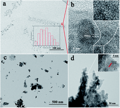
The morphologies of Cu/MoS2 NAS and Cu/MoS2 NSs were characterized by transmission electron microscopy (TEM). Fig. 1a gives a close-up view of Cu nanoparticles (NPs) uniformly distributed on MoS2. The mean size of Cu NPs, extracted by directly measuring 138 particles from the TEM, is estimated to be approximately 5.8 nm. Fig. 1b shows an HRTEM image of the Cu/MoS2 NAS with a lattice spacing of 0.24 nm, corresponding to the (111) plane of Cu.22 Also visible is the clear lattice fringes of MoS2. As shown in Fig. 1c and Fig. S2,† TEM was used to observe the morphology of Cu/MoS2 NSs, in which Cu NPs (with a diameter of 12.5 nm) aggregated on the surface of MoS2 NSs. HRTEM (Fig. 1d) indicated that having many highly crystalline Cu NPs covering the edges of MoS2 NSs may lead to the reduction of HER electrocatalytic performance. | ||
| Fig. 1 TEM images of Cu/MoS2 NAS (a) and Cu/MoS2 NSs (c). HRTEM images of Cu/MoS2 NAS (b), and Cu/MoS2 NSs (d). | ||
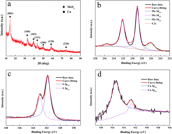
Fig. 2a shows the XRD pattern of the Cu/MoS2 NAS. For the pattern of the sample, the peaks at 2θ = 14.2°, 33.0°, 39.7°, and 59.1° are attributed to the (002), (100), (103) and (110) planes of MoS2.23 The peaks of Cu at 43.5°, 50.5° and 74.5° in the range of 40–80° can be assigned to the diffraction from the (111), (200), (220) planes of reductive Cu NPs with cubic phase, respectively.24 XPS spectra were recorded to gain further insights into the chemical nature and bonding state of the Cu/MoS2 NAS. As shown in Fig. 2b, the high-resolution Mo 3d XPS spectrum contains two strong characteristic peaks at 228.9 eV and 231.9 eV, which can be attributed to the Mo4+ oxidation state,25 while the relatively weak peak detected at 235.7 eV corresponds to the Mo6+ oxidation state (the latter feature most likely resulted from the formation of a very small amount of MoO3 species during catalyst preparation). Hence, the majority of the synthesized Mo species exhibited an oxidation state of +4. Furthermore, the high-resolution S 2p1/2 and S 2p3/2 spectra, which were centred at 161.8 eV and 162.9 eV, respectively, revealed the presence of divalent S2− ions (Fig. 2c).26 After peak deconvolution of Cu 2p3/2 in Fig. 2d, XPS spectrum peaks centred at 935.4 and 932.7 eV can be assigned as CuO and Cu2S.27
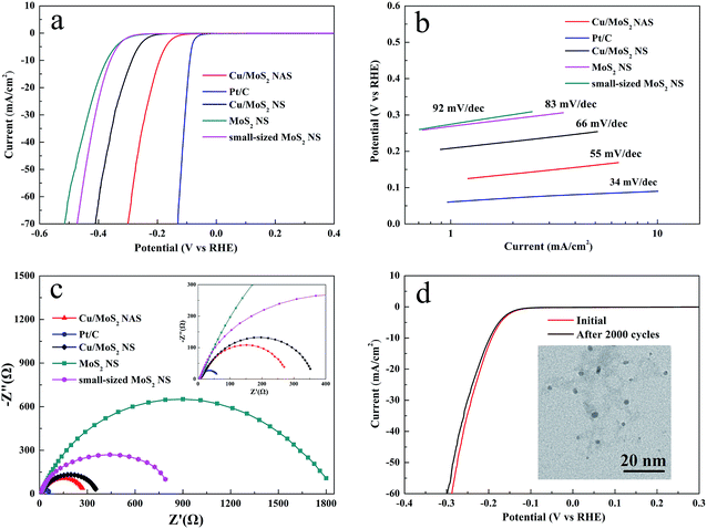
Different polarization curves obtained for the studied catalysts via LSV are shown in Fig. 3a. It was found that the Pt/C catalyst exhibited very strong HER performance with an overpotential close to zero, while the Cu/MoS2 NAS was characterized by a small overpotential of approximately 120 mV. For comparison, small-sized MoS2 NSs without CuCl2·2H2O are fabricated by using a similar method to that described for Cu/MoS2 NAS synthesized (Fig. S3 and S4†). In a sharp contrast, both the Cu/MoS2 NSs, pure MoS2 NSs, and small-sized MoS2 NSs exhibited poor HER electrocatalytic activity. The linear segments of the corresponding Tafel plots (Fig. 3b) were fit with the Tafel equation η = b × lg![[thin space (1/6-em)]](https://www.rsc.org/images/entities/char_2009.gif) j + a, where j is the current density, and b is the Tafel slope. As a result, the Tafel slopes of 92, 83, 66, 55, and 34 mV per decade were obtained for MoS2 NSs, small-sized MoS2 NSs, Cu/MoS2 NSs, Cu/MoS2 NAS, and Pt/C catalyst, respectively. It is indicated that the improved performance of the catalyst is contributed to the introducing of Cu NPs which is in accordance with previous reports.20,21 The high HER catalytic activity of the prepared Cu/MoS2 NAS catalyst can be attributed to the strong electronic coupling between the Cu and MoS2. To maximize this effect, impedance measurements were performed at an overpotential of η = 120 mV. As shown in Fig. 3c, the same amount of the Cu/MoS2 NAS catalyst exhibited an alternating current impedance of approximately 275 Ω, which was much lower than that of the MoS2 NSs (approximately 1800 Ω) and Cu/MoS2 NSs (approximately 370 Ω).
j + a, where j is the current density, and b is the Tafel slope. As a result, the Tafel slopes of 92, 83, 66, 55, and 34 mV per decade were obtained for MoS2 NSs, small-sized MoS2 NSs, Cu/MoS2 NSs, Cu/MoS2 NAS, and Pt/C catalyst, respectively. It is indicated that the improved performance of the catalyst is contributed to the introducing of Cu NPs which is in accordance with previous reports.20,21 The high HER catalytic activity of the prepared Cu/MoS2 NAS catalyst can be attributed to the strong electronic coupling between the Cu and MoS2. To maximize this effect, impedance measurements were performed at an overpotential of η = 120 mV. As shown in Fig. 3c, the same amount of the Cu/MoS2 NAS catalyst exhibited an alternating current impedance of approximately 275 Ω, which was much lower than that of the MoS2 NSs (approximately 1800 Ω) and Cu/MoS2 NSs (approximately 370 Ω).
 | ||
| Fig. 3 Polarization curves for catalysts (a) and the corresponding Tafel plots (b). Impedance spectroscopy at an overpotential of 120 mV (c). Durability test for the Cu/MoS2 NAS (d). | ||
To further evaluate the long-term stability of the synthesized Cu/MoS2 NAS catalyst, cyclic voltammetry (CV) measurements by scanning 2000 cycles from −300 mV to 300 mV (vs. RHE) with a scan rate of 100 mV s−1 in an acidic environment (0.5 M H2SO4) was used. Fig. 3d shows the comparison of polarization curves of the catalyst during the first cycle and 2000th cycle. The almost overlapped curves indicate the negligible loss of the catalytic performance and a remarkable stability of the Cu/MoS2 NAS catalyst.28 In addition, the TEM images depicted in the insert of Fig. 3d show that the original morphology of the hybrid catalyst was well preserved after acidic treatment.
Remarkably, Tafel slopes are one of the most significant factors that can discern the HER mechanism. According to the classic theory,29 Tafel slopes for the typical Volmer, Heyrovsky, and Tafel reactions are around of 120 mV dec−1, 40 mV dec−1, and 30 mV dec−1, respectively (1–3). The following are the now accepted steps by which HER in acidic aqueous media described, where MHads represents a hydrogen atom chemically adsorbed on an active site of various material (M). In view of the Tafel slope of 55 mV dec−1 for the Cu/MoS2 NAS catalyst in the current work, a combination of the Volmer reaction, involving an electrochemical desorption step that converts protons into absorbed hydrogen atoms on the catalyst surface, and the Heyrovsky reaction, involving the formation of surface scope hydrogen molecules, should dominate the HER on the catalytic process of the Cu/MoS2 NAS catalyst. In other words, the rate determining step is the electrochemical desorption of Hads and H3O+ to form hydrogen, and the HER occurs through a Volmer–Heyrovsky mechanism.
| H3O+ + e− + C → MHads + H2O | (1) |
| H3O+ + e− + MHads → C + H2 + H2O | (2) |
| MHads + MHads → 2M + H2 | (3) |
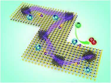
To elucidate the synergistic effect produced by the synthesized Cu/MoS2 NAS catalyst on the catalytic process in more detail, a simple model (Fig. 4) can be considered. The obtained hybrid contains a large number of active HER catalytic sites due to the abundance of accessible edges resulting from the small size and irregular shape of MoS2. The use of Cu NPs not only improved the electrical conductivity of the catalyst but also further enhanced the catalytic activity by a synergistic effect with nano-sized MoS2. Therefore, the produced Cu/MoS2 NAS catalyst can effectively reduce dissociated H+ ions and release H2 molecules on a large number of active sites.
 | ||
| Fig. 4 Schematic illustration of the mechanism governing the electrocatalytic HER on the Cu/MoS2 NAS. | ||
4. Conclusions
In summary, a facile microwave-assisted method has been used to synthesize a Cu/MoS2 NAS catalyst for HER. TEM images show that Cu NPs can disperse on MoS2 uniformly, which improves conductivity. The Cu/MoS2 NAS exhibits excellent HER catalytic properties and long cycle life, which is attributed to the excellent electrical coupling between the Cu NPs and the nano-sized MoS2. Therefore, this work describes an inexpensive method for the efficient fabrication of a Cu/MoS2 NAS catalyst for the HER.Acknowledgements
The work described in this paper was financially supported by the National Natural Science Foundation of China (No. 61404037 and No. 61376113).Notes and references
- H. I. Karunadasa, C. J. Chang and J. R. Long, Nature, 2010, 464, 1329–1333 CrossRef CAS PubMed.
- J. A. Turner, Science, 2004, 305, 972–974 CrossRef CAS PubMed.
- J. S. Luo, J. H. Im, M. T. Mayer, M. Schreier, M. K. Nazeeruddin, N. G. Park, S. D. Tilley, H. J. Fan and M. Grätzel, Science, 2014, 345, 1593–1596 CrossRef CAS PubMed.
- M. G. Walter, E. L. Warren, J. R. McKone, S. W. Boettcher, Q. Mi, E. A. Santori and N. S. Lewis, Chem. Rev., 2010, 110, 6446–6473 CrossRef CAS PubMed.
- C. Chen, Y. J. Kang, Z. Y. Huo, Z. G. Zhu, W. Y. Huang, H. L. Xin, J. D. Snyder, D. Li, J. A. Herron, M. Mavrikakis, M. Chi, K. L. More, Y. Li, N. M. Markovic, G. A. Somorjai, P. Yang and V. R. Stamenkovic, Science, 2014, 343, 1339–1343 CrossRef CAS PubMed.
- T. Ye, L. B. Lv, M. Xu, B. Zhang, K. X. Wang, J. Su, X. H. Lin and J. S. Chen, Nano Energy, 2015, 15, 335–342 CrossRef CAS.
- Y. Shi, J. Wang, C. Wang, T. T. Zhai, W. J. Bao, J. J. Xu, X. H. Xia and H. Y. Chen, J. Am. Chem. Soc., 2015, 137, 7365–7370 CrossRef CAS PubMed.
- F. K. Ma, Y. Z. Wu, Y. L. Shao, Y. Y. Zhong, J. X. Lv and X. P. Hao, Nano Energy, 2016, 27, 466–474 CrossRef CAS.
- W. X. Zhu, C. Tang, D. N. Liu, J. L. Wang, A. M. Asiric and X. P. Sun, J. Mater. Chem. A, 2016, 4, 7169–7173 CAS.
- Y. J. Tang, Y. Wang, X. L. Wang, S. L. Li, W. Huang, L. Z. Dong, C. H. Liu, Y. F. Li and Y. Q. Lan, Adv. Energy Mater., 2016, 6, 1600116 CrossRef.
- Y. C. Zhoua, Y. H. Leng, W. J. Zhou, J. L. Huang, M. W. Zhao, J. Zhan, C. H. Feng, Z. H. Tang, S. W. Chen and H. Liu, Nano Energy, 2015, 16, 357–366 CrossRef.
- B. W. Jin, X. M. Zhou, L. Huang, M. Licklederer, M. Yang and P. Schmuki, Angew. Chem., Int. Ed., 2016, 55, 12252–12256 CrossRef CAS PubMed.
- T. F. Jaramillo, K. P. Jørgensen, J. Bonde, J. H. Nielsen, S. Horch and I. Chorkendorff, Science, 2007, 317, 100–102 CrossRef CAS PubMed.
- J. Bonde, P. G. Moses, T. F. Jaramillo, J. K. Nørskovb and I. Chorkendorff, Faraday Discuss., 2008, 140, 219–231 RSC.
- B. Hinnemann, P. G. Moses, J. Bonde, K. P. Jørgensen, J. H. Nielsen, S. Horch, I. Chorkendorff and J. K. Nørskov, J. Am. Chem. Soc., 2005, 127, 5308–5309 CrossRef CAS PubMed.
- Z. Y. Zhang, W. Y. Li, M. F. Yuena, T. W. Nga, Y. B. Tang, C. S. Lee, X. F. Chenc and W. J. Zhang, Nano Energy, 2015, 18, 196–204 CrossRef CAS.
- Q. H. Wang, K. K. Zadeh, A. Kis, J. N. Coleman and M. S. Strano, Nat. Nanotechnol., 2012, 7, 699–712 CrossRef CAS PubMed.
- M. B. Gawande, A. Goswami, F. X. Felpin, T. Asefa, X. X. Huang, R. Silva, X. X. Zou, R. Zboril and R. S. Varma, Chem. Rev., 2016, 116, 3722–3811 CrossRef CAS PubMed.
- D. Merki and X. Hu, Energy Environ. Sci., 2011, 4, 3878–3888 CAS.
- F. Li, J. Li, X. Lin, X. Li, Y. Fang, L. Jiao, X. An, Y. Fu, J. Jin and R. Li, J. Power Sources, 2015, 300, 301–308 CrossRef CAS.
- F. Li, L. Zhang, J. Li, X. Lin, X. Li, Y. Fang, J. Huang, W. Li, M. Tian, J. Jin and R. Li, J. Power Sources, 2015, 292, 15–22 CrossRef CAS.
- R. Krishna, D. M. Fernandes, J. Ventura, C. Freire and E. Titus, Int. J. Hydrogen Energy, 2016, 41, 11608–11615 CrossRef CAS.
- G. Du, Z. Guo, S. Wang, R. Zeng, Z. Chen and H. Liu, Chem. Commun., 2010, 46, 1106–1108 RSC.
- J. Luo, S. Jiang, H. Zhang, J. Jiang and X. Liu, Anal. Chim. Acta, 2012, 709, 47–53 CrossRef CAS PubMed.
- B. J. Guo, K. Yu, H. L. Li, H. L. Song, Y. Y. Zhang, X. Lei, H. Fu, Y. H. Tan and Z. Q. Zhu, ACS Appl. Mater. Interfaces, 2016, 8, 5517–5525 CAS.
- K. C. Pham, Y. H. Chang, D. S. McPhail, C. Mattevi, A. T. S. Wee and D. H. C. Chua, ACS Appl. Mater. Interfaces, 2016, 8, 5961–5971 CAS.
- M. Sam, M. R. Bayati, M. Mojtahedi and K. Janghorban, Appl. Surf. Sci., 2010, 257, 1449–1453 CrossRef CAS.
- H. Deng, C. Zhang, Y. Xie, T. Tumlin, L. Giri, S. P. Karna and J. Lin, J. Mater. Chem. A, 2016, 4, 6824–6830 CAS.
- J. G. N. Thomas, Trans. Faraday Soc., 1961, 57, 1603–1611 RSC.
Footnote |
| † Electronic supplementary information (ESI) available: Experimental details. See DOI: 10.1039/c7ra01605k |
| This journal is © The Royal Society of Chemistry 2017 |

