DOI:
10.1039/C7RA01056G
(Paper)
RSC Adv., 2017,
7, 18883-18891
Lithium adsorption performance of a three-dimensional porous H2TiO3-type lithium ion-sieve in strong alkaline Bayer liquor†
Received
24th January 2017
, Accepted 20th March 2017
First published on 28th March 2017
Abstract
Removing lithium from the Bayer liquor for ensuring good alumina product quality demands a special lithium ion-sieve (LIS) with good stability in a strong alkaline medium. In this study, a three-dimensional porous H2TiO3-type LIS (porous-HTO) prepared by a polystyrene (PS) colloidal microspheres template was applied to adsorb Li+ from the strong alkaline Bayer liquor. XRD and SEM results confirm the fine stability of porous-HTO in strong alkaline medium, and the regeneration tests show that more than 64 mg g−1 lithium adsorption capacity still remains even after 5 cycles of lithiation–delithiation in the simulation Bayer liquor. The lithium adsorption processes of porous-HTO and bare H2TiO3-type LIS (bare-HTO) both fit the pseudo-second-order model, but the adsorption capacity and the adsorption rate of the porous-HTO are much better than those of the bare-HTO. For porous-HTO, the adsorption rate constant is 0.02357 g mg−1 h−1 and the equilibrium adsorption capacity is 76.3 mg g−1, while for bare-HTO, the adsorption rate constant is 0.009682 g mg−1 h−1 and the equilibrium adsorption capacity is only 44.8 mg g−1. The lithium selectivity tests demonstrate that the coexisting ions including Na+, K+, AlO2−, SiO32− in the simulation Bayer liquor have low influence on lithium adsorption. The simulation Bayer liquors with Li+ ions of 56.00, 30.00 and 5.00 mg L−1 are all reduced to below 1.00 mg L−1 by virtue of one-time-adsorption of porous-HTO at various solid to liquid ratios of 1.0, 0.5 and 0.1 g L−1, respectively.
Introduction
The Bayer process for producing refined smelter grade alumina has been applied for more than 100 years in industry.1–6 In the Bayer leaching process, the Bayer liquor containing a high concentration caustic sodium solution (ca. 200 g L−1) is circularly used for alumina leaching. With cycle number increases, some impurities (mainly oxides and hydroxides of Si, Ga, and V, etc.) brought from bauxite would accumulate in the Bayer liquor, which might reduce the purity of the alumina product in industry. In the past decades, researchers have used several methods such as fractional precipitation method, electrochemical method, solvent extraction method, and ion exchange method, etc. to remove Si, Ga, and V from the Bayer liquor.7–13 Recently, it has been reported that a kind of lithium-containing bauxite used for alumina production suffers from lithium enrichment (50–100 mg L−1) in the Bayer liquor, which has seldom been encountered in previous studies.14,15 Due to high dissolubility of most lithium salts, it is hard to remove lithium impurities by precipitation/co-precipitation methods from the Bayer liquor. In addition, considering the economic applicability in alumina industry, some reported conventional methods for lithium recovery from salt-lake brines or seawater such as solar evaporation method, solvent extraction method and hydrometallurgical method are all unsuitable.16–19
In the past few years, some materials were found to possess selective lithium adsorption performance by virtue of special Li+ screen crystal structures (either spinel structure or layered structure); correspondingly, these materials were called lithium ions sieves (LISs). The LISs have been proven to be efficient for recovering lithium ions from aqueous solution.20–25 However, most reported studies about LISs focused on neutral and weak alkaline medium although some of them involved the effect of alkalinity on lithium adsorption. Wang et al.26 confirmed that manganese-type LISs (Mn-LISs) were unstable in alkaline solution: the lithium adsorption capacity increased as alkalinity grew in the range of pH 7–12 but more than 1% of Mn dissolved when pH reached 13. The instability of Mn-LISs in strong alkaline medium might be caused by the serious Jahn–Teller distortion of Mn3+ during the Li+ insertion process in spinels.27,28 In this regard, titanium-type LISs (Ti-LISs) display better stability in strong alkaline medium because no Jahn–Teller distortion occurs and the Ti–O bond energy is higher than the Mn–O bond energy.25 Till now, although a few of studies have reported the lithium adsorption activities of Ti-LISs in weak alkaline solution (e.g. 0.1 mol L−1 LiOH, alkali-added seawater, etc.),29,30 the lithium adsorption performance in strong alkaline solution has not been explored.
The objective of the present study is trying to remove lithium ions from the Bayer liquor by the layered H2TiO3-type LIS (HTO), which is a typical Ti-LIS. In order to improve the lithium recovery performance in strong alkaline Bayer liquor, a three-dimensional (3D) porous H2TiO3-type LIS (porous-HTO) was prepared by a polystyrene (PS) colloidal microspheres template. The lithium adsorption kinetics, regeneration performance and lithium selectivity of the porous-HTO were investigated by comparing those of the bare H2TiO3-type LIS (bare-HTO). In addition, some suitable solid to liquid ratios of both porous-HTO and bare-HTO were suggested for lithium removal from the simulation Bayer liquors with different lithium concentrations in industry. This study offers a feasible way for lithium removal from the Bayer liquor and widens the practical application area of Ti-LIS.
Experimental section
LISs preparation
Bare-HTO. The precursor of the bare-HTO was obtained by a sol–gel method. The synthesis process started from dissolving Ti[O(CH2)3CH3]4 and LiNO3 (mole ratio 1![[thin space (1/6-em)]](https://www.rsc.org/images/entities/char_2009.gif) :2) in 150 mL ethyl alcohol, followed by adding 25 mL CH3COOH to the above solution dropwise under constant stirring. After stirring for 30 min, a mixed solution containing 10 mL deionized water and 30 mL ethyl alcohol was dropped into this blend to turn the transparent solution into white sol. Then the sol was heated at 60 °C for 24 h in water bath environment to form light yellow gel. The light yellow dry gel powder was obtained by heating the gel at 120 °C for 12 h. In the crystallization process, the dry gel powder was heated to a final temperature of 800 °C at a rate of 2 °C min−1 and kept at 800 °C for 4 h in the air to form the bare precursor (bare-LTO). After cooling to the ambient temperature, the bare-LTO was treated by 0.2 mol L−1 HCl solution with occasional shaking for 4 h at 60 °C (1 g of solid in 1 L solution). Finally, the white bare-HTO powder was obtained by filtrating and drying.
:2) in 150 mL ethyl alcohol, followed by adding 25 mL CH3COOH to the above solution dropwise under constant stirring. After stirring for 30 min, a mixed solution containing 10 mL deionized water and 30 mL ethyl alcohol was dropped into this blend to turn the transparent solution into white sol. Then the sol was heated at 60 °C for 24 h in water bath environment to form light yellow gel. The light yellow dry gel powder was obtained by heating the gel at 120 °C for 12 h. In the crystallization process, the dry gel powder was heated to a final temperature of 800 °C at a rate of 2 °C min−1 and kept at 800 °C for 4 h in the air to form the bare precursor (bare-LTO). After cooling to the ambient temperature, the bare-LTO was treated by 0.2 mol L−1 HCl solution with occasional shaking for 4 h at 60 °C (1 g of solid in 1 L solution). Finally, the white bare-HTO powder was obtained by filtrating and drying.
Porous-HTO. The PS microspheres were synthesized by an emulsion polymerization method.31,32 First, 0.5 g cetane trimethyl ammonium bromide (CTAB) was dissolved in 150 mL deionized water. Second, 0.1 g ammonium persulfate (APS) as the initiator and 20 g styrene as the monomer were added to the above solution. Third, N2 was piped into the reactor for 0.5 h to remove the residual O2. After stirring for 24 h at 65 °C, a white stable emulsion was formed. Finally, the emulsion was placed in a vacuum freezing drying oven and kept for 120 h, thus obtaining white PS microspheres powders.The porous-HTO was prepared by using PS microspheres as template. The precursor solution was obtained by adding solution A (6.81 g LiNO3 dissolved in 100 mL ethanol and 0.6 mL H2O) to solution B (3.40 g Ti[O(CH2)3CH3]4, 50 mL ethanol and 1.80 g acetic acid) dropwise under vigorous stirring for 1 h. Then the PS microspheres powders were soaked in the above solution for 0.5 h, followed by centrifugation and drying under vacuum at 40 °C for 2 h. The above operations were repeated for 3 times until the precursor solution penetrated the voids of PS templates completely. The obtained powder was calcined in a muffle to remove the PS template with a heating rate of 2 °C min−1 and kept at 300 °C for 2 h, then heated up to 800 °C at the same rate and kept for 4 h. After that the precursor of porous-HTO (porous-LTO) was obtained. Finally, the porous-LTO was immersed in 0.2 mol L−1 HCl for 4 h at 60 °C, then the porous-HTO was obtained after being filtered, washed and dried.
Characterizations
Structures and morphologies. The X-ray diffract (XRD) pattern of the samples was performed using Rigaku Smartlab X-ray diffractometer system equipped with graphite-monochromatized Cu/Kα radiation (λ = 1.5406 Å). The scanning rate was 5° min−1 in the 2θ range of 10–90°, operating at 40 kV and 40 mA. The X-ray photoelectron spectroscopy (XPS) spectra was measured with a Physical Electronics ESCA5800 spectrometer equipped with a monochromatic Al Kα X-ray source (E = 1486.6 eV). The scanning step and working pressure were 0.1 eV and 2 × 10⁻⁷ Pa, respectively. The morphologies of the materials were studied by scanning electron microscopy (SEM, HITACHI, TM3000) using an accelerating voltage of 5 kV with a vacuum of 1 × 10⁻⁶ Pa and a resolution of 30 nm.
Lithium recovery process. The regeneration performance of bare-HTO and porous-HTO was tested in the procedure as follows: 0.1 g bare-HTO or porous-HTO was immersed in 1.0 L Li+-containing strong alkaline solution (6.0 mol L−1 NaOH containing 56.00 mg L−1 Li+) and kept under magnetic stirring for 24 h at room temperature. The suspensions were filtered and the Li+ concentration in the filter liquor was determined by an Inductively Coupled Plasma-Atomic Emission Spectrometry (ICP-AES, Shimadzu ICPS-75000). The residual solids were washed with deionized water for further delithiation. In delithiation process, the residues were treated with 0.2 mol L−1 HCl solution at 60 °C and kept under magnetic stirring for 4 h. The lithiation–delithiation operations were repeated for 5 cycles. The titanium contents in bare-HTO and porous-HTO were determined by the methylene blue–ascorbic acid colorimetric method after it was dissolved in 40 mL nitric acid and 20 mL hydrochloric acid in a heating condition.33The adsorption kinetics and the adsorption selectivity were tested in the simulation Bayer liquor, which is a 6.0 mol L−1 NaOH solution containing 66.81 mg L−1 Li+, 56.79 mg L−1 K+, 70.46 mg L−1 AlO2−, and 56.79 mg L−1 SiO32−. For the adsorption kinetics, Li+ ions concentration was determined at a certain time (t = 0, 1, 2, 4, 6, 8, 12, 18, 24 h). The adsorption selectivity behavior of LISs was determined by analyzing the concentration change of all ions in the simulation Bayer liquor. The distribution coefficient (Kd), separation factor (αLiMe) and concentration factor (CF) were calculated by the eqn (1)–(3):
| |
 | (1) |
| |
 | (2) |
| |
 | (3) |
where
C0(Me) is the initial concentration of each metal ion,
Ce(Me) is the equilibrium concentration of each metal ion,
V is the volume of the simulation solution,
W is the mass of LIS and
Qe(Me) is the equilibrium adsorption capability of each metal ions by LISs.
Results and discussion
Lithium extraction from porous-LTO
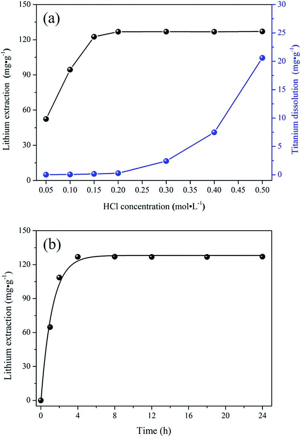
The lithium extraction from porous-LTO experiments were designed for choosing the optimal acid pickling condition for preparing the porous lithium ion-sieve. The results are shown in Fig. 1. Fig. 1a presents the lithium extraction and titanium dissolution upon treatment of porous-LTO with different HCl solution. When the hydrochloric acid concentrations are lower than 0.2 mol L−1, the extracted lithium amounts increase with the hydrochloric acid concentration and the titanium dissolution amounts keep at a low level (less than 0.1 mg g−1). In this concentration range, the activity of H+ in solution plays a vital role for the chemical potentials equilibrium of lithium in both solid and solution, more Li+ can be replaced by the H+ in high H+ activity solution upon Li+–H+ ion exchange reaction. Meanwhile, low titanium dissolution indicates that the material is stable enough in this concentration range. When hydrochloric acid concentrations are not lower than 0.2 mol L−1, the extracted lithium amounts keep at maximum values of approximately 127.3 mg g−1 (the theoretical value of Li+ content in the Li2TiO3) and the titanium dissolution amounts increase significantly. Nearly 100% extracted Li+ amounts demonstrate that the Li+–H+ ion exchange reaction is completed in this range, and the increasing dissolved titanium dissolution amounts imply that the layered structure is not stable in high concentration hydrochloric acid solution. Therefore, the optimal concentration of hydrochloric acid solution for treating porous-LTO should be 0.2 mol L−1. On the other hand, the bare Li2TiO3 (bare-LTO) treated in 0.2 mol L−1 hydrochloric acid solution at 60 °C for 24 h also exhibits 99.9% extracted Li+ amount and only 0.82% dissolved Ti4+ amount, indicating 0.2 mol L−1 hydrochloric acid solution is also fitted for the pickling process of bare-LTO. Fig. 1b shows the lithium extraction rates from porous-LTO in 0.2 mol L−1 hydrochloric acid concentration. Obviously, the lithium extraction amount increases with time in the initial 4 h and keeps in maximum value (ca. 127.3 mg g−1) in the following time, indicating pickling for 4 h in 0.2 mol L−1 hydrochloric acid solution at 60 °C is enough to ensure a complete Li+ extraction from the porous-LTO. Also, this condition is fitted for completely converting the bare-LTO to the bare-HTO. In summary, the optimal acid pickling condition should be treating the porous-LTO in 0.2 mol L−1 of hydrochloric acid solution for 4 h at 60 °C.
 |
| | Fig. 1 (a) Lithium extraction and dissolution of titanium upon treatment of porous-LTO with different HCl solutions; (b) the lithium extraction rate from porous-LTO with 0.2 mol L−1 HCl solution. | |
Structure characterization
Crystal structures. The XRD patterns of both bare and porous materials are shown in Fig. 2. For the bare-LTO (curve a), the diffraction peaks at 2θ = 18.469°, 20.165°, 35.861°, 43.582°, 47.754°, 57.565°, 63.486°, 66.735° are assigned to the monoclinic Li2TiO3 (C2/c space group, JCPDS card 33-0831).34 Similarly, the XRD pattern of porous-LTO (curve b) could also be indexed as the monoclinic Li2TiO3, indicating the existence of PS templates during the preparation does not affect the crystallization of Li2TiO3. After acid treatment, the XRD patterns of both bare-HTO (curve c) and porous-HTO (curve d) change dramatically in comparison to their precursors: the peak of (020) shifts to left but the peaks of (002) and (−131) shift to right slightly, the peaks of (−131) and (−133) turn wide, and the peaks of (−133), (−206) and (062) all disappear. This change is well consistent with previous work,20,29,30 which is possibly ascribed to different bonding ways between Li and H in Ti–O layers. Meanwhile, curve c and d are quite similar, implying the first pickling process on porous-LTO is similar to that on bare-LTO, the PS-modified precursor also shows the same Li–H exchange process in Ti–O layered.
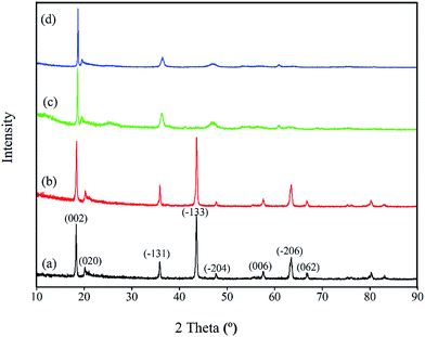 |
| | Fig. 2 XRD patterns of (a) the bare-LTO, (b) the porous-LTO, (c) the bare-HTO, and (d) the porous-HTO. | |
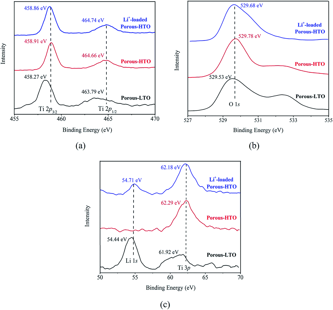
The further XPS examination (shown in Fig. 3) verifies that the patterns of HTO before and after loading lithium ions from strong alkaline solution (6.0 mol L−1 NaOH containing 56.00 mg L−1 Li+) are different (the full spectra see Fig. S1 in ESI†). Through precision survey, the Ti2p, O1s, and Li1s peaks are shown in Fig. 3a, b and c, respectively. In Fig. 3a, the binding energy values of Ti 2p1/2 and Ti 2p3/2 peaks for porous-LTO are 463.79 eV and 458.27 eV, respectively, increasing slightly for both porous-HTO (464.66 and 458.91 eV) and Li+-loaded porous-HTO (464.74 and 458.86 eV). The binding energy values of Ti 2p1/2 and Ti 2p3/2 peaks for porous-HTO and Li+-loaded porous-HTO are very close.35–37 In Fig. 3b, the binding energy value of O1s peak for porous-LTO is 529.53 eV, increasing slightly for both porous-HTO (529.78 eV) and Li+-loaded porous-HTO (529.68 eV) likewise. The binding energy values of O1s peak value for porous-HTO and Li+-loaded porous-HTO are also quite alike. The similar binding energy variation trend of Ti2p and O1s demonstrates the chemical structure of porous-HTO are different from that of porous-LTO, but similar with that of Li+-loaded porous-LTO; in other words, the chemical environments of Ti and O have irreversibly changed after first acid treatment. The reason could be attributed to different impacts of Li and H on Ti–O layers: owing to different radius of Li+ (ca. 0.76 Å) and H+ (ca. 0.012 Å), the space occupancy of H+ is much smaller than that of Li+, and the formed HTO layers is more flexible than the LTO. Thus, the interaction between Ti and O weakens and the Ti–O bond lengthens after first acid treatment, resulting further structural transformation. In the later Li adsorption process, Li+ ions are probably accommodated into the HTO with the electrostatic force.29 In Fig. 3c, the Li1s exhibits the highest relative intensity (vs. Ti3p) on porous-LTO at binding energy of 54.44 eV, while it almost disappears on porous-HTO and reappears on Li+-loaded porous-HTO at binding energy of 54.71 eV. However, the relative intensity on Li+-loaded porous-HTO is lower than that on porous-LTO, suggesting the lithium content in Li+-loaded sample is lower than that in initial precursor sample. The structural change of porous materials is consistent with previous work for bare materials, indicating the PS modification has no impact on Li adsorption mechanism.38
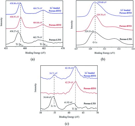 |
| | Fig. 3 XPS images of (a) Ti2p spectra, (b) O1s spectra and (c) Li1s spectra. | |
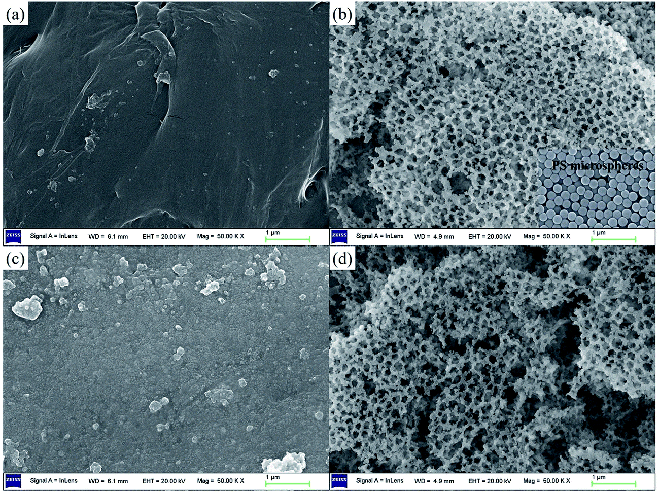
Surface morphology. The SEM images of the materials are shown in Fig. 4. The bare-LTO displays a smooth surface (Fig. 4a), while the porous-LTO exhibits regular honeycomb porous structure (Fig. 4b), which is attributed to the 3D ordered self-assembly colloidal PS microspheres (for details see Fig. S2 in ESI†). Fig. 4c presents the surface morphology of bare-HTO. The results suggest the alterations of the solid particle surface after delithiation are not remarkably visible. In Fig. 4d, the honeycomb-like structure of the porous-HTO is also retained after Li+ ions are exchanged with protons, suggesting the impact of both water molecules and Li–H ions exchange reaction on the change in porous structure is limited.
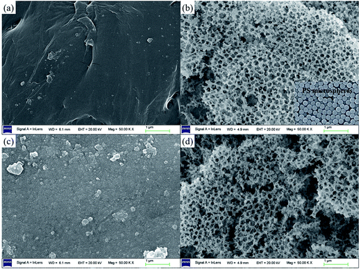 |
| | Fig. 4 SEM images of (a) bare-LTO, (b) porous-LTO, (c) bare-HTO, and (d) porous-HTO. | |
Specific surface areas. BET results in Table 1 demonstrate the specific surface area change of bare and porous samples. It is obvious that the specific surface area of porous samples is 8–10 times as large as bare samples. The results turn out that PS modification shows remarkable improvement in surface area of the materials. Besides, the surface areas of both bare-HTO and porous-HTO are larger than that of the corresponding LTO, which may be attributed to the preferential adsorption on acid adsorption sites.29
Table 1 BET surface areas of LTO and HTO
| BET surface areas (m2 g−1) |
| Bare samples |
Bare-LTO |
5.92 |
| Bare-HTO |
12.87 |
| Porous samples |
Porous-LTO |
67.61 |
| Porous-HTO |
94.14 |
Adsorption kinetics
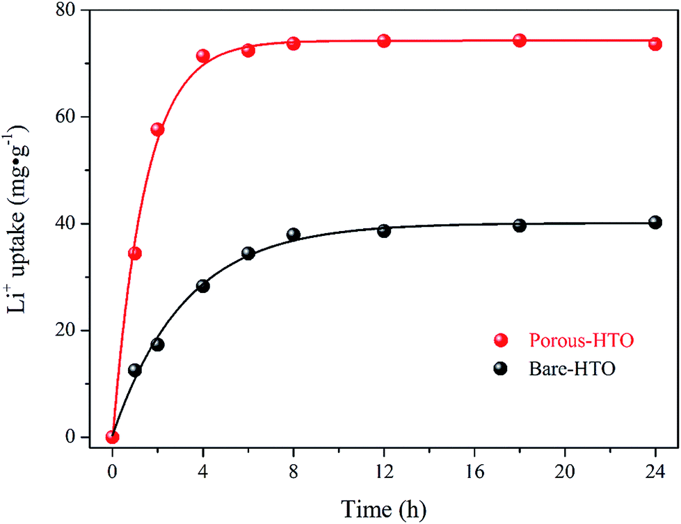
The adsorption kinetics of lithium ions on both bare-HTO and porous-HTO in the simulation Bayer liquor (6.0 mol L−1 NaOH, 56.00 mg L−1 Li+) were investigated to determine the lithium adsorption rate and establish the equilibrium lithium adsorption capacity. As shown in Fig. 5, the curves of Li+ uptake by the two adsorbents rise fast in the initial period followed by becoming flat afterwards. However, the Li+ adsorption equilibrium time and the capacity of the two adsorbents are different: about 4 h are needed for the porous-HTO to reach equilibrium, which is much shorter than that of bare-HTO (ca. 8 h). The practical equilibrium lithium capacity on porous-HTO is about 70 mg g−1, which is much higher than that of bare-HTO (ca. 40 mg g−1).
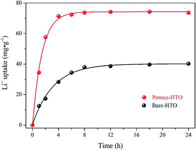 |
| | Fig. 5 Li+ uptake kinetics of both bare-HTO and porous-HTO in the simulation Bayer liquor. | |
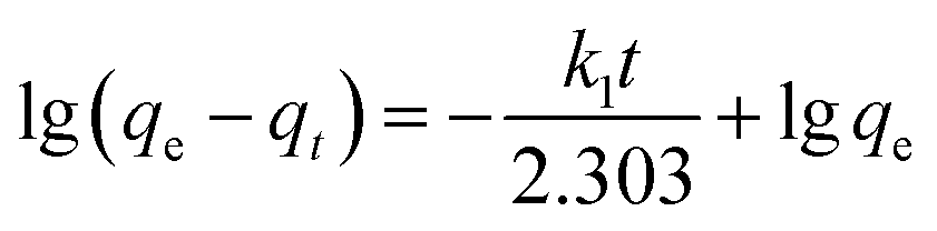
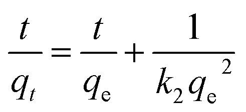
Two kinds of kinetics models of pseudo-first-order kinetic model (eqn (4)) and pseudo-second-order kinetic model (eqn (5))39,40 were applied to investigate the lithium adsorption kinetic behaviors:
| |
 | (4) |
| |
 | (5) |
In above equations, qe and qt are the equilibrium lithium capacity and the lithium adsorption capacity in the time of t; k1 and k2 represent the adsorption rate constants of pseudo-first-order kinetic model and pseudo-second-order kinetic model respectively. All of the kinetic parameters were calculated according to the slope and the intercept of the fitted-lines. The fitting results are shown in Table 2 (the fitting curves are illustrated in Fig. S3 in ESI†).
Table 2 Kinetics parameters for Li+ adsorption on both bare-HTO and porous-HTO in the simulation Bayer liquor at room temperature
| Fitting models |
Parameters |
Bare-HTO |
Porous-HTO |
| Pseudo-first-order |
k1 (h−1) |
0.2411 |
0.3749 |
| qe (mg g−1) |
40.2 |
74.4 |
| R2 |
0.9434 |
0.8846 |
| Pseudo-second-order |
k2 (g mg−1 h−1) |
0.009682 |
0.02357 |
| qe (mg g−1) |
44.8 |
76.3 |
| R2 |
0.9946 |
0.9980 |
As shown in Table 2, it is more likely to describe Li+ adsorption on porous-HTO in the simulation Bayer liquor as a pseudo-second-order kinetic process because the linear correlation coefficient of the pseudo-second-order dynamic equation (0.9980) is better than that of pseudo-first-order dynamic equation (0.8846). Similarly, the process of Li+ adsorption on bare-HTO could also be described as a pseudo-second-order dynamic process. The results suggest the rate-determining factors in lithium adsorption on HTO are related with not only the lithium concentration in liquid phase but also the quantity of active lithium adsorption sites in the solid phase. In other words, under the premise of constant lithium concentration in solution, large surface area of the adsorbent is beneficial for improving the lithium adsorption rate in the simulation Bayer liquor because larger surface area has more active Li+ adsorption sites. Just as the results indicate, the rate constants for the bare-HTO and porous-HTO are 0.009682 and 0.02357 g mg−1 h−1, respectively.
Moreover, the porous-HTO also presents higher practical equilibrium lithium adsorption capacity than the bare one (76.3 mg g−1 vs. 44.8 mg g−1). This may be attributed to the superior permeability of porous-HTO because porous-HTO provides a short diffusion pathway for lithium ions so that the Li+/H2TiO3 contact is improved effectively. Consequently, the inner solid particles of the porous-HTO play an effective role in lithium ions adsorption, and the apparent lithium adsorption amount could be enhanced as compared with bare-HTO. In summary, by virtue of the PS modification on adsorbent, the mass transfer efficiency between solid adsorbent and lithium ions in simulation Bayer liquor is improved effectively, and the corresponding lithium recovery performance including both the lithium adsorption rate and the practical lithium adsorption capacity is enhanced remarkably.
Regeneration performance
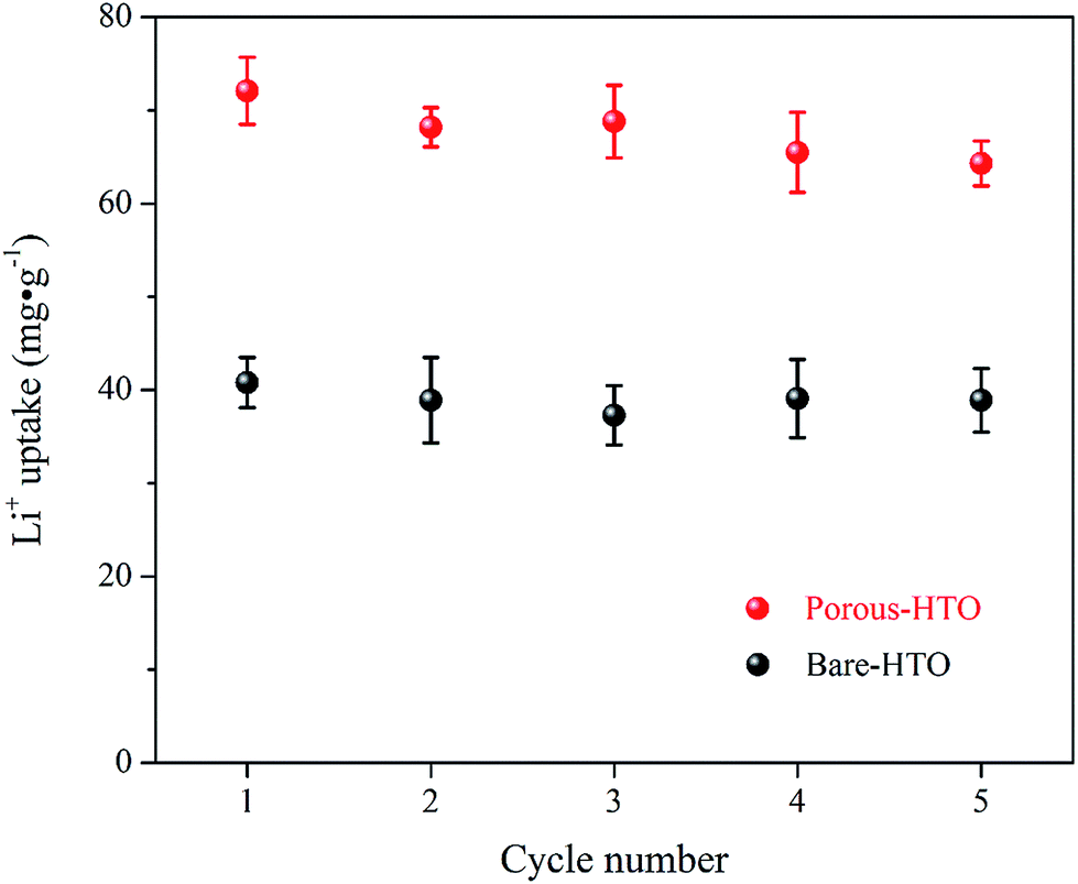
Fig. 6 shows lithium uptake change by both bare-HTO and porous-HTO during 5 cycles of lithiation–delithiation in the simulation Bayer liquor (6.0 mol L−1 NaOH, 56.00 mg L−1 Li+). It is observed that the lithium adsorption capacities of bare-HTO and porous-HTO both remains at a relatively stable level in 5 cycles' operations, implying the H2TiO3-type lithium ion-sieves have good stability in strong alkaline medium. Notably, the lithium adsorption capacity fading of porous-HTO (about 10.81%) is slight higher than that of bare-HTO (about 4.65%), which is possibly caused by the destruction of pore structures in cyclic operations (Fig. 8a). On the other hand, the dissolution rate of Ti for both bare-HTO and porous-HTO in each cycle are less than 0.5 wt%, indicating the dissolution of both adsorbents are quite limited. However, as the comparison shows, the Li+ uptake amount of λ-MnO2 in 6.0 mol L−1 NaOH solution decreases sharply at the second cycle due to the dissolution of Mn (the detailed lithium recovery performance of λ-MnO2 in strong alkaline medium are illustrated in Fig. S4 in ESI†). The results strongly demonstrate that Ti-LISs are more stable than Mn-LISs in strong alkaline medium, so it is appropriate to choose the Ti-LISs as the lithium adsorbent for recovering Li+ from strong alkaline medium.
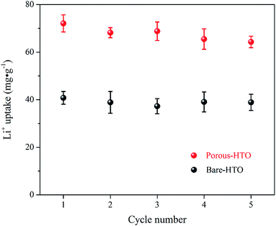 |
| | Fig. 6 Regeneration performances of both bare-HTO and porous-HTO in the simulation Bayer liquor. | |
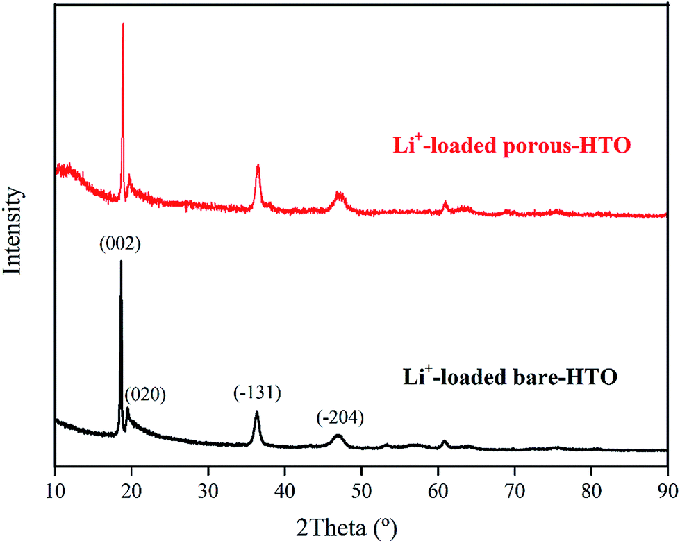
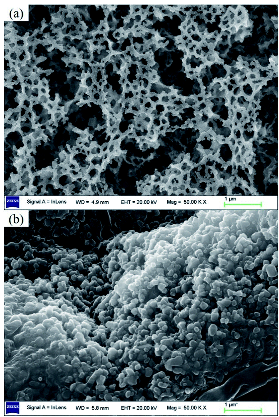
The XRD patterns of Li+-loaded bare-HTO and Li+-loaded porous-HTO after 5 cycle operation are shown in Fig. 7. All of the diffraction peaks derived from (002), (020), (−131), and (−204) crystal faces are the same as those of porous-HTO (shown in Fig. 2d), and no extra peaks appear. The results manifest both Li+-loaded bare-HTO and Li+-loaded porous-HTO keep fine crystallinity even if the operation is at the 5th cycle. On the other hand, in Fig. 8, the SEM images of porous-HTO after 5 times of Li+-loading still possess the porous structure which is almost similar to the as-prepared one shown in Fig. 4 except for occurrence of a slight collapse of the porous structure. Based on the above results, it is concluded that both two adsorbents present fine regeneration performance in the simulation Bayer liquor, although the porous-HTO shows slight higher Li+ adsorption capacity fading degree than the bare-HTO, the practical Li+ adsorption capacity of porous-HTO is higher than another one.
 |
| | Fig. 7 XRD patterns of both Li+-loaded porous-HTO and Li+-loaded bare-HTO after 5 cycle operation. | |
 |
| | Fig. 8 SEM images of (a) Li+-loaded porous-HTO and (b) Li+-loaded bare-HTO after 5 cycle operation. | |
Adsorption selectivity
The results of adsorption selectivity of lithium ions to other coexisted ions in the simulation Bayer liquor on both porous-HTO and bare-HTO are listed in Table 3. For both adsorbents, the equilibrium distribution coefficient (Kd) for Li+ and other ions are evaluated as Li+ ≫ K+ > SiO32− ≈ AlO2−. Apparently, the Li+ ions are preferentially adsorbed by both adsorbents on the whole. In addition, the separation factors (αLiMe) of Li+ to other coexisting ions in the simulation Bayer liquor are much higher than 1.00, and the Li+ concentration factor (CF) value of both adsorbents are far above those of other ions (577.49 of bare-HTO and 908.40 of porous-HTO), indicating the existence of K+, AlO2−, and SiO32− does not interfere with Li+ during the adsorption process. The above results demonstrate that (1) the layered H2TiO3-type ion-sieve has high selectivity to Li+ but much low to all other ions, (2) the modification of PS microspheres almost has no effect on lithium selectivity of the adsorbent.
Table 3 Lithium selectivity on bare-HTO and porous-HTO in the simulation Bayer liquora
| Ions |
Bare-HTO |
Porous-HTO |
| C0 (mg L−1) |
Ce (mg L−1) |
Qe (mg g−1) |
Kd (mL g−1) |
αLiMe |
CF (L mg−1) |
C0 (mg L−1) |
Ce (mg L−1) |
Qe (mg g−1) |
Kd (mL g−1) |
αLiMe |
CF (L mg−1) |
| Notes: C0 is the initial concentration of each metal ion; Ce is the equilibrium concentration of each metal ion; Qe is the calculated equilibrium adsorption capability of each metal ions by LISs; Kd is the calculated equilibrium distribution coefficient and αLiMe is the calculated separation factors. |
| Li+ |
66.81 |
28.23 |
38.58 |
1366.63 |
1.00 |
577.49 |
66.81 |
6.12 |
60.69 |
9916.67 |
1.0 |
908.40 |
| K+ |
56.79 |
54.12 |
2.67 |
49.33 |
27.70 |
47.02 |
56.79 |
54.28 |
2.51 |
46.24 |
214.45 |
44.20 |
| AlO2− |
70.46 |
69.83 |
0.63 |
9.02 |
151.48 |
8.94 |
70.46 |
69.11 |
1.35 |
19.53 |
507.66 |
19.16 |
| SiO32− |
84.57 |
82.25 |
2.32 |
28.21 |
48.45 |
27.43 |
84.57 |
84.01 |
0.56 |
6.67 |
1487.68 |
6.62 |
On the other hand, it is hard to determine the change in concentration of Na+ ions in the simulation Bayer liquor because the concentration of Na+ is far higher than that of Li+ (mass ratio Na:Li = 2066:1). In order to investigate the influence of Na+ ions on lithium adsorption, an additional experiment was performed: same quantity of sodium ions and lithium ions (ca. 60.0 mg L−1) was dissolved in 1 L 6.0 mol L−1 KOH aqueous solution, then 1.00 g of adsorbent was added and kept for 24 h under stirring. The results show that the equilibrium adsorption capacity of Li+ on the porous-HTO is 53.67 mg L−1 and that of Na+ is only 0.65 mg L−1. The αLiNa value is 770.99, and the CF value of Li and Na is 893.90 and 10.81 respectively, revealing that Na+ does not interfere with Li+ during the adsorption process. That is to say, the huge quantity of sodium ions existing in the simulation Bayer liquor presents low influence on lithium adsorption, and the modification of PS microspheres has no adverse impact on the lithium selectivity from the simulation Bayer liquor (the results were listed in Table S1 in ESI†).
Dosage
Different amount of the bare-HTO and porous-HTO was added to the 1.0 L simulation Bayer liquors with different Li+ concentrations. In dosage tests, the criterion of residual Li+ concentration in simulation Bayer liquor is set as below 1.0 mg L−1, which is acceptable in alumina industrial production. The results of lithium removal after one-time adsorption are listed in Table 4. For the initial Li+ concentration of 56.00 mg L−1 (no. 1, 3 and 6), the remaining Li+ is decreased to below 1.0 mg L−1 when using 1.0 g L−1 porous-HTO of at least 1.0 g L−1. In comparison, for achieving the same Li removal effect, at least 2.0 g L−1 of bare-HTO are required. If the initial concentration of Li+ ions is lower, the required dosage of the LIS would be smaller. For instance, for the simulation Bayer liquors with Li+ ions of 40.00 mg L−1 (no. 4 and 7) and 30.00 mg L−1 (no. 5, 8 and 11), in order to reduce Li+ ions to below 1.00 mg L−1, 1.0 and 0.5 g L−1 porous-HTO are needed respectively, while 1.0 g L−1 bare-HTO is needed for both liquors. Notably, for the simulation Bayer liquor with 5.00 mg L−1 of initial Li+ ions, although the residual Li+ concentration by using larger doses (no. 10 and no. 14) is slight higher than that by using 0.1 g porous-HTO (no. 15), which is caused by small measuring errors in practical operations, only 0.1 g L−1 porous-HTO is enough to ensure the residual Li+ concentration decreases to below 1.0 mg L−1 (no. 15).
Table 4 Lithium removal effects from simulation Bayer liquor by the porous-HTO and bare-HTO with different dosage
| No. |
Initial Li+ concentration (mg L−1) |
Dosage of LIS (g L−1) |
Remaining Li+ concentration (mg L−1) |
| Porous-HTO |
Bare-HTO |
| 1 |
56.00 |
2.0 |
0.04 |
0.06 |
| 2 |
60.00 |
1.0 |
1.17 |
30.04 |
| 3 |
56.00 |
1.0 |
0.98 |
26.45 |
| 4 |
40.00 |
1.0 |
0.02 |
0.57 |
| 5 |
30.00 |
1.0 |
0.04 |
0.09 |
| 6 |
56.00 |
0.5 |
32.58 |
34.88 |
| 7 |
40.00 |
0.5 |
12.43 |
23.63 |
| 8 |
30.00 |
0.5 |
0.82 |
11.47 |
| 9 |
20.00 |
0.5 |
0.01 |
0.62 |
| 10 |
5.00 |
0.5 |
0.05 |
0.02 |
| 11 |
30.00 |
0.2 |
19.90 |
22.61 |
| 12 |
20.00 |
0.2 |
7.80 |
11.06 |
| 13 |
10.00 |
0.2 |
0.04 |
1.95 |
| 14 |
5.00 |
0.2 |
0.01 |
0.01 |
| 15 |
5.00 |
0.1 |
0.04 |
1.28 |
Conclusions
The H2TiO3-type lithium ion-sieve was proven to have fine structural stability in strong alkaline medium, and the adsorption kinetic studies show Li+ ions adsorbed by HTO follows the pseudo-second-order kinetic model, suggesting that the adsorption kinetic is correlated with the quantity of active sites on LIS. As one of promising methods to remove lithium ions from the strong alkaline Bayer liquor, a 3D porous-HTO prepared by PS template method was prepared. Comparing with the bare-HTO, the equilibrium lithium adsorption capacity and the rate constant of the porous-HTO have been improved significantly. In addition, the adsorption selectivity, regeneration performance of both porous-HTO and bare-HTO were proven to be fine in simulation Bayer liquor. Under optimum conditions, 56.00 mg L−1 of Li+ ions in Bayer liquor can be decreased to less than 1.0 mg L−1 by adding 1.0 g L−1 porous-HTO after just one time adsorption. In our future work, technology improvement of the recovery utilization rate of the powder materials and reduction of energy consumption will be studied.
Conflict of interest
The authors declare no competing financial interest.
Acknowledgements
The authors greatly appreciate the support from the National Natural Science Foundation of China (No. 51374016, 21506010), the Fundamental Research Funds for the Central Universities of China (No. YS1406, JD1515) and BUCT Fund for Disciplines Construction and Development (No. XK1525, XK1531).
References
- G. Power, J. S. C. Loh, J. E. Wajon, F. Busetti and C. Joll, Anal. Chim. Acta, 2011, 689, 8–21 CrossRef CAS PubMed.
- S. Ruan, L. Shi, J. Li and A. R. Gerson, Hydrometallurgy, 2016, 163, 1–8 CrossRef CAS.
- Y. L. Sidrak, Ind. Eng. Chem. Res., 2001, 40, 1146–1156 CrossRef CAS.
- E. VanDalen and L. G. Ward, Anal. Chem., 1974, 46, 1826 CrossRef.
- A. Buvari-barcza, M. Rozsahegyi and L. Barcza, J. Mater. Chem., 1998, 8, 451–455 RSC.
- E. VanDalen and L. G. Ward, Anal. Chem., 1973, 45, 2248–2251 CrossRef CAS.
- X. Pan, H. Yu, G. Tu and S. Bi, Hydrometallurgy, 2016, 165(2), 261–269 CrossRef CAS.
- L. Zeng and Z. Li, Ind. Eng. Chem. Res., 2012, 51, 15193–15206 CrossRef CAS.
- Z. Zhao, Y. Yang, Y. Xiao and Y. Fan, Hydrometallurgy, 2012, 125–126, 115–124 CrossRef CAS.
- P. Selvi, M. Ramasami, M. H. P. Samuel, P. Adaikkalam and G. N. Srinivasan, Ind. Eng. Chem. Res., 2004, 43, 2216–2221 CrossRef CAS.
- B. Gupta, N. Mudhar and S. N. Tandon, Ind. Eng. Chem. Res., 2005, 44, 1922–1927 CrossRef CAS.
- Z. Zhao, H. Long, X. Li, Y. Fan and Z. Han, Hydrometallurgy, 2012, 115–116, 52–56 CrossRef CAS.
- M. D. Okudan, A. Akcil, A. Tuncuk and H. Deveci, Hydrometallurgy, 2015, 152, 76–83 CrossRef CAS.
- G. Kuang, H. Li, S. Hu, R. Jin, S. Liu and H. Guo, Hydrometallurgy, 2015, 157, 214–218 CrossRef CAS.
- P. Meshram, B. D. Pandey and T. R. Mankhand, Hydrometallurgy, 2014, 150, 192–208 CrossRef CAS.
- Z. Zhou, W. Qin, S. Liang, Y. Tan and W. Fei, Ind. Eng. Chem. Res., 2012, 51, 12926–12932 CrossRef CAS.
- Z. Xu, H. Zhang, R. Wang, W. Gui, G. Liu and Y. Yang, Ind. Eng. Chem. Res., 2014, 53, 16502–16507 CrossRef CAS.
- T. Tran and V. T. Luong, in Lithium Process Chemistry, ed. J. Światowska, Elsevier, Amsterdam, 2015, pp. 81–124, DOI:10.1016/B978-0-12-801417-2.00003-7.
- J. W. An, D. J. Kang, K. T. Tran, M. J. Kim, T. Lim and T. Tran, Hydrometallurgy, 2012, 117–118, 64–70 CrossRef CAS.
- R. Chitrakar, Y. Makita, K. Ooi and A. Sonoda, Dalton Trans., 2014, 43, 8933–8939 RSC.
- R. Chitrakar, H. Kanoh, Y. Miyai and K. Ooi, Chem. Mater., 2000, 12, 3151–3157 CrossRef CAS.
- S.-Y. Sun, X. Song, Q.-H. Zhang, J. Wang and J.-G. Yu, Adsorption, 2011, 17, 881–887 CrossRef CAS.
- Q. Feng, Y. Miyai, H. Kanoh and K. Ooi, Chem. Mater., 1993, 5, 311–316 CrossRef CAS.
- R. Chitrakar, Y. Makita, K. Ooi and A. Sonoda, Ind.
Eng. Chem. Res., 2014, 53, 3682–3688 CrossRef CAS.
- X. Xu, Y. Chen, P. Wan, K. Gasem, K. Wang, T. He, H. Adidharma and M. Fan, Prog. Mater. Sci., 2016, 84, 276–313 CrossRef CAS.
- L. Wang, C. G. Meng and W. Ma, Colloids Surf., A, 2009, 334, 34–39 CrossRef CAS.
- S. Ghose, M. Kersten, K. Langer, G. Rossi and L. Ungaretti, Phys. Chem. Miner., 1986, 13, 291–305 CrossRef CAS.
- A. Yamada and M. Tanaka, Mater. Res. Bull., 1995, 30, 715–721 CrossRef CAS.
- C. P. Lawagon, G. M. Nisola, J. Mun, A. Tron, R. E. C. Torrejos, J. G. Seo, H. Kim and W.-J. Chung, J. Ind. Eng. Chem., 2016, 35, 347–356 CrossRef CAS.
- X.-c. Shi, Z.-b. Zhang, D.-f. Zhou, L.-f. Zhang, B.-z. Chen and L.-l. Yu, Trans. Nonferrous Met. Soc. China, 2013, 23, 253–259 CrossRef CAS.
- L. J. Fu, T. Zhang, Q. Cao, H. P. Zhang and Y. P. Wu, Electrochem. Commun., 2007, 9, 2140–2144 CrossRef CAS.
- Y. Cao, Y. Wang, Y. Zhu, H. Chen, Z. Li, J. Ding and Y. Chi, Superlattices Microstruct., 2006, 40, 155–160 CrossRef CAS.
- M. H. Zavvar and N. Pourreza, J. Chin. Chem. Soc., 2008, 55, 750–754 CrossRef.
- Y.-z. Hao, Q.-l. Zhang, J. Zhang, C.-r. Xin and H. Yang, J. Mater. Chem., 2012, 22, 23885–23892 RSC.
- G. He, J. Gao, H. Chen, J. Cui, Z. Sun and X. Chen, ACS Appl. Mater. Interfaces, 2014, 6, 22013–22025 CAS.
- G. He, J. Liu, H. Chen, Y. Liu, Z. Sun, X. Chen, M. Liu and L. Zhang, J. Mater. Chem. C, 2014, 2, 5299–5308 RSC.
- J. W. Zhang, G. He, L. Zhou, H. S. Chen, X. S. Chen, X. F. Chen, B. Deng, J. G. Lv and Z. Q. Sun, J. Alloys Compd., 2014, 611, 253–259 CrossRef CAS.
- G. He, L. Zhang, D. Zhou, Y. Zou and F. Wang, Ionics, 2015, 21, 2219–2226 CrossRef CAS.
- T. Ryu, J. Shin, D.-H. Lee, J. Ryu, I. Park, H. Hong, Y. S. Huh, B.-G. Kim and K.-S. Chung, Hydrometallurgy, 2015, 157, 39–43 CrossRef CAS.
- Y. S. Ho and G. McKay, Water Res., 2000, 34, 735–742 CrossRef CAS.
Footnote |
| † Electronic supplementary information (ESI) available: Details regarding XPS image of full spectra for porous-LTO, porous-HTO, and Li+-loaded porous-HTO, SEM images of 3D order self-assembly colloidal PS microspheres, kinetic fitting plots, lithium adsorption performance of Mn-LIS in strong alkaline solution, and lithium and sodium adsorption comparison by both porous-HTO and bare-HTO in the simulation Bayer liquor. See DOI: 10.1039/c7ra01056g |
|
| This journal is © The Royal Society of Chemistry 2017 |
Click here to see how this site uses Cookies. View our privacy policy here. 
 Open Access Article
 This Open Access Article is licensed under a
  ab,
Yanzhi Sunab,
Yongmei Chen*ab and
Pingyu Wanab
ab,
Yanzhi Sunab,
Yongmei Chen*ab and
Pingyu Wanab