 Open Access Article
Creative Commons Attribution 3.0 Unported Licence
Mesoporous C, N-codoped TiO2 hybrid shells with enhanced visible light photocatalytic performance†
Minggui Wang,
Jie Han *,
Yimin Hu and
Rong Guo*
School of Chemistry and Chemical Engineering, Yangzhou University, Yangzhou, Jiangsu 225002, P. R. China. E-mail: hanjie@yzu.edu.cn; guorong@yzu.edu.cn
First published on 8th March 2017
Abstract
Mesoporous C, N-codoped TiO2 (C/N-TiO2) hybrid shells incorporated with graphite carbon were synthesized using polystyrene spheres as templates, followed by polyaniline (PANI) and TiO2 coating, and then post-treatments of etching and calcination, where PANI functioned as both C and N doping sources and supplied the graphite carbon. Compared with pure TiO2 and C-doped TiO2 (C-TiO2) hybrid shells, C/N-TiO2 hybrid shells exhibited enhanced photocatalytic activity in the degradation of organic dyes and H2 production under visible light irradiation, which could be attributed to the enhanced visible light absorption and charge separation efficiency associated with the codoped-C and N and the presence of graphite carbon. It is believed that the strategy presented here will provide a promising route for the construction of other C/N-semiconductor hybrid shells for broader applications.
Introduction
Titania (TiO2), as one of the photocatalysts with the most potential, has been widely investigated for energy storage and environmental treatment,1 owing to its low cost, non-toxicity, stability and high photocatalytic activity.2 However, the photocatalytic activity of pure TiO2 is still very low, mainly due to its relatively large band gap which can only be excited by UV light and the high rate of recombination of photogenerated electron–hole pairs.3 To solve these problems, many effective strategies have been made to improve the photocatalytic activity by enhancing its visible light absorption and improving the separation efficiency of electron–hole pairs.4 One common approach for shifting the light absorption of TiO2 to the visible region is to change its inner band structure by replacing the oxygen in the lattice to narrow the band gap. Recently, efforts have been focused on introducing non-metallic elements into TiO2 to enhance its photocatalytic activity (such as C, N, S, B and F).5 It has been reported that the introduction of these non-metallic elements can shift the light absorption of TiO2 to the visible light region to enhance the visible light absorption and corresponding photocatalytic activity. Among these non-metallic elements-doped TiO2 materials, C or N-doped TiO2-based composites have attracted increasing attention in particular. In the process of C doping, C element can produce a hybrid orbital over the valence band of TiO2 to decrease the band gap with enhanced visible light absorption.6 As for N doping, it has been reported that doped N can act as trapping centers for photogenerated electrons and effectively suppresses the recombination rate of the photogenerated electrons and holes.7 Although many studies have been focused on the preparation of C or N-doped TiO2, however, little work has done on the construction of C, N-codoped TiO2 (C/N-TiO2). It is believed that C/N-TiO2 will be of highly interest because it possesses both enhanced visible light absorption and separation efficiency of electron–hole pairs, which can contribute to improved photocatalytic activity.Polyaniline, as one of the most promising conducting polymers, has been widely studied due to its low cost, ease preparation, high environmental stability, and novel special structure-related properties.8 It involves both N and C elements with relatively high molar ratio of N to C at 1/6, which can be chosen as the potential doping source for N and C codoping in TiO2 within a one-step process. More importantly, in comparison with commonly used gaseous dopants, such as NH3,9 PANI is economical, and can be fully utilized during the doping process with the additional graphite carbon acts as electrically conductive components to improve the transmission of photogenerated electrons.10 Therefore, designed-synthesis of C/N-TiO2 hybrids as powerful photocatalysis using PANI as doping sources is of highly important.
Herein, mesoporous C/N-TiO2 hybrid shells have been successfully fabricated through in situ polymerization and sol–gel coating method. The calcination route is applied to synthesize C/N-TiO2 hybrid shells where PANI functions as both C and N doping sources and supplies the graphite carbon, which help to improve the visible light absorption and photogenerated electron–hole pair separation efficiency of TiO2, and finally lead to enhanced photocatalytic activity. To the best of our knowledge, this is the first report of one step C, N-codoping of TiO2 using PANI as the dopant. Results from catalytic investigations of C/N-TiO2 hybrid shells toward the degradation of organic pollutions and H2 production under visible light irradiation indicate that C and N codoping can remarkably improve the photocatalytic performance of TiO2. The superior photocatalytic performance of C/N-TiO2 hybrid shells clearly indicates their potential as low-cost but powerful visible light photocatalysts.
Experimental
Materials
Tetrabutyl orthotitanate (TBOT, 97%) was obtained from Fluka. Anhydrous ethanol, rhodamine B (RhB), ammonia (25–28%), hydrochloric acid (HCl), acetonitrile, styrene monomer, methacrylic acid, ammonium persulfate (APS), and all other reagents were obtained from Sinopharm Chemical Reagent Co. Ltd. (China). Aniline monomer was distilled under reduced pressure. The water used in this study was deionized and purified through a Millipore system.Synthesis of polystyrene (PS) nanoparticles
In a typical synthesis, styrene monomer (35.0 mL) was mixed with deionized water (150.0 mL), methacrylic acid (1.0 mL) and an aqueous solution of APS (1.0 mL H2O containing 0.1575 g APS). After stirring for 3 h under 95 °C, the PS nanoparticles were separated by centrifugation, washed three times with ethanol, and then dried under vacuum at 50 °C for 6 h.Synthesis of PS/PANI core/shell hybrids
In typical, 111.4 μL aniline was added to 15.0 mL water at ice bath and under ultrasonic treatment for 15 min, followed by the addition of the 0.568 g PS. The mixture was stirred with ultrasonic assistance for 30 min at ice bath. Then 7.0 mL APS aqueous solution (0.045 g mL−1) was added to the dispersion. After stirring for 5 min, an aqueous solution of HCl (1.4 mL H2O containing 114.8 μL HCl) solution was slowly added. After stirring for 4 h at ice bath, the particles were isolated by centrifugation and washed with ethanol, and then dried in an oven at 80 °C for 6 h.Synthesis of mesoporous C/N-TiO2 hybrid shells
In typical, 20.0 mg of as-prepared PS/PANI hybrids were dispersed in a mixture of ethanol (25.0 mL) and acetonitrile (7.0 mL) under vigorous stirring. After adding ammonia aqueous solution (0.2 mL), TBOT (0.4 mL) in a mixture of ethanol (3.0 mL) and acetonitrile (1.0 mL) was injected into the mixture. After stirring for 3 h, the PS/PANI/TiO2 hybrids were isolated by centrifugation and washed with ethanol, and then dispersed in 20.0 mL tetrahydrofuran (THF) under vigorous stirring for 5 h to completely remove the PS template, the PANI/TiO2 hybrids were isolated by centrifugation and washed with ethanol, and then dried in an oven at 80 °C for 6 h. After that, the PANI/TiO2 hybrids were calcined under N2 protection at different temperature (500–800 °C) for 4 h to crystallize TiO2, and carbonize PANI through pyrolysis. By controlling the calcination temperature at 500, 600, 700, and 800 °C, the as-prepared C/N-TiO2 hybrid shells were denoted as C/N-TiO2(500), C/N-TiO2(600), C/N-TiO2(700), and C/N-TiO2(800), respectively.Synthesis of pure TiO2 and C-TiO2 hybrid shells
In typical, 15.0 mg PS nanoparticles were dispersed in a mixture of ethanol (25.0 mL) and acetonitrile (7.0 mL) under vigorous stirring. After adding ammonia aqueous solution (0.2 mL), TBOT (0.4 mL) in a mixture of ethanol (3.0 mL) and acetonitrile (1.0 mL) was injected into the mixture. After stirring for 3 h, the particles were isolated by centrifugation and washed with water, and then dried in an oven at 80 °C for 6 h. After that, the PS/TiO2 core/shell hybrids were calcined under air and N2 protection at 600 °C for 4 h to produce TiO2(600) and C-TiO2(600).Photocatalytic activity tests
Characterization
Morphologies were characterized with a transmission electron microscopy (TEM, JEM-2100) and a high-resolution TEM (HRTEM, Tecnai G2 F30 S-Twin TEM, FEI). The crystal phase was analyzed by XRD using a Bruker AXS D8 ADVANCE X-ray diffractometer. The specific surface and pore size were studied by using a Beishide 3H-2000PS2 analysis instrument. UV/Vis diffuse reflectance spectra (Cary 5000, Varian) was used to test the optical properties. The phase composition was measured using an Axis Ultra X-ray photoelectron spectroscope (XPS, Kratos Analytical Ltd., UK) equipped with a standard monochromatic Al Kα source (hv = 1486.6 eV). Photoluminescence (PL) spectra were measured using a fluorescence spectrophotometer (Hitachi F-7000), and the excitation wavelength was 315 nm. The total organic carbon (TOC) values of RhB solution were determined using a total organic carbon analyzer (Elementar vario TOC). The oxygen vacancies of the as-prepared samples were studied by electron paramagnetic resonance (EPR) measurements (A300-10/12, Bruker).Results and discussion
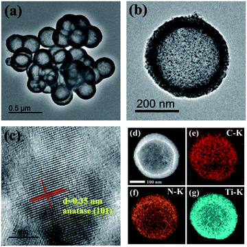
Scheme 1 illustrates the procedures for preparing mesoporous C/N-TiO2 hybrid shells. Specifically, PS nanospheres were used as templates, loaded sequentially with layers of PANI and TiO2 by in situ polymerization and sol–gel methods, respectively. Finally, the PS templates were removed and then PANI/TiO2 hybrid shells are calcined under N2 atmosphere, leading to the formation of C/N-TiO2 hybrid shells.Fig. S1† shows the morphology evolution from PS templates to PS/PANI/TiO2 hybrids. Fig. 1a and b present the typical low and high magnified TEM images of C/N-TiO2(600) hybrid shells, where the shell thickness is ∼40 nm, and the particle size distribution of C/N-TiO2(600) hybrid shells from a statistical study of the TEM images was given in Fig. S2.† The HRTEM image (Fig. 1c) indicates that the lattice fringes of 0.35 nm match the plane of anatase TiO2 (101). The hollow structure of C/N-TiO2(600) hybrid shells can be further confirmed by high-angle annular dark-field scanning transmission electron microscope (HAADF-STEM), as shown in Fig. 1d. The corresponding energy dispersive X-ray spectroscopic (EDS) mapping of C, N and Ti are shown in Fig. 1e–g, indicating the homogeneous distribution of C and N elements in TiO2 shell.
The calcination temperature is found to affect the morphology of C/N-TiO2 hybrid shells. As shown in Fig. 2, it can be clearly found that the final hollow structure can be well maintained at the calcination temperature below 700 °C. When the calcination temperature reaches 800 °C, the hybrid shells are aggregated and the shell grains are grown into big particles.
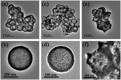 | ||
| Fig. 2 TEM images of (a, b) C/N-TiO2(500), (c, d) C/N-TiO2(700), and (e, f) C/N-TiO2(800) hybrid shells. | ||
In order to clarify the C/N codoping effect, pure TiO2 and C-TiO2 hybrid shells were also synthesized using a similar strategy. As started from PS which only contains C element, TiO2 shell is then coated on surfaces of PS, followed by calcination under N2 atmosphere, leading to the formation of C-TiO2 hybrid shells. If the calcination is placed under air condition, carbon can be completely removed and then pure TiO2 hollow spheres can be obtained. Fig. S3† gives the typical TEM images of pure TiO2(600) hollow spheres and C-TiO2(600) hybrid shells. It can be seen that pure TiO2(600) hollow spheres maintains the hollow structure but with some broken shells, whereas C-TiO2(600) can maintain the complete hollow structures. The tenacity of doped TiO2 hybrid shells (Fig. 1 and S1b†) is obviously superior to that of undoped TiO2 hybrid shells (Fig. S1a†), which may be attributed to the presence of graphite carbon resulted from PANI carbonization (as confirmed later by Raman spectra) that bridges TiO2 crystalline grains and improves the shell integrity.
The chemical composition and element valence of C/N-TiO2(600) hybrid shells as studied by XPS analysis are shown in Fig. 3. The XPS survey spectrum (Fig. 3a) of C/N-TiO2(600) hybrid shells indicates the presence of Ti, C, O and N elements. The C 1s spectrum of C/N-TiO2(600) hybrid shells are shown in Fig. 3b. The peaks at 284.8, 285.9, 287.0, and 288.9 eV are ascribed to the binding energy of sp2 C–C, C–N, C![[double bond, length as m-dash]](https://www.rsc.org/images/entities/char_e001.gif) N and C–O–Ti bonds, respectively. The N 1s spectra of C/N-TiO2(600) hybrid shells (Fig. 3c) can be attributed to pyridine N (398.3 eV), quaternary N (400.6 eV) and oxidized N (403.0 eV). Results indicate the successful C/N cooping in TiO2.11 Fig. 3d is the high resolution Ti 2p spectra of pure TiO2(600) hollow spheres and C/N-TiO2(600) hybrid shells. It can be seen that TiO2 hybrid shells show two peaks at 458.1 and 463.8 eV, which contribute to the binding energies of Ti 2p3/2 and Ti 2p1/2 levels, respectively, indicating a normal state of Ti4+.12 In addition, in contrast to pure TiO2(600) hollow spheres, the Ti 2p binding energy of C/N-TiO2(600) hybrid shells shifts toward high energy, which may be attributed to the C/N codoping in TiO2.
N and C–O–Ti bonds, respectively. The N 1s spectra of C/N-TiO2(600) hybrid shells (Fig. 3c) can be attributed to pyridine N (398.3 eV), quaternary N (400.6 eV) and oxidized N (403.0 eV). Results indicate the successful C/N cooping in TiO2.11 Fig. 3d is the high resolution Ti 2p spectra of pure TiO2(600) hollow spheres and C/N-TiO2(600) hybrid shells. It can be seen that TiO2 hybrid shells show two peaks at 458.1 and 463.8 eV, which contribute to the binding energies of Ti 2p3/2 and Ti 2p1/2 levels, respectively, indicating a normal state of Ti4+.12 In addition, in contrast to pure TiO2(600) hollow spheres, the Ti 2p binding energy of C/N-TiO2(600) hybrid shells shifts toward high energy, which may be attributed to the C/N codoping in TiO2.
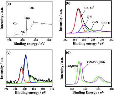 | ||
| Fig. 3 (a) The survey, (b) C 1s and (c) N 1s XPS spectra of C/N-TiO2(600) hybrid shells. (d) Ti 2p XPS spectra of pure TiO2(600) hollow spheres and C/N-TiO2(600) hybrid shells. | ||
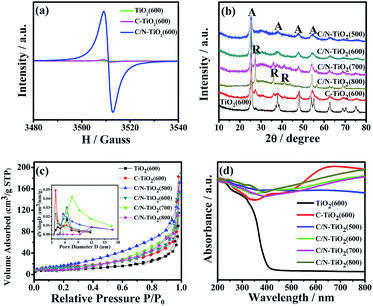
In addition, the electron paramagnetic resonance (EPR) was also used to investigate the oxygen vacancies in the samples. As shown in Fig. 4a, the pure TiO2(600) hollow spheres, C-TiO2(600) and C/N-TiO2(600) hybrid shells show a resonance at about g = 2.000, which is attributed to the signal of oxygen vacancy. It has been reported that the stronger peak intensity of EPR spectra suggesting the higher existing oxygen vacancy.13 Moreover, it can be seen from Fig. 4a that the signal intensity of oxygen vacancy increased with the doping of the C and N into TiO2, indicating an increased concentration of oxygen vacancy in C-TiO2(600) and C/N-TiO2(600) samples. The more oxygen vacancies indicate the higher degree of doping.
The phase structures of pure TiO2(600) hollow spheres, C-TiO2(600) and C/N-TiO2(600) hybrid shells were investigated by XRD analysis and the results were presented in Fig. 4b. Most of the identified peaks for TiO2 are assigned to anatase (JCPDS, no. 73-1764). However, it also can be observed that a small rutile diffraction peak at 27.5° in pure TiO2(600) hollow spheres and C-TiO2(600) hybrid shells, suggesting the presence of rutile phase. Notably, as for C/N-TiO2 hybrid shells, the intensity and sharpness of the XRD peaks are strengthened with increasing calcination temperature, suggesting increased crystallinity of TiO2 grains. When the calcination temperature reaches above 700 °C, such as C/N-TiO2(800), rutile phase TiO2 is the dominating phase.
The specific surface area and pore structure of pure TiO2(600) hollow spheres, C-TiO2(600) and C/N-TiO2 hybrid shells were characterized by N2 adsorption–desorption analysis. It has been reported that the high specific surface areas can favor increased photocatalytic activity.14 Fig. 4c displays N2 adsorption–desorption isotherms and their corresponding pore size distribution curves. It can be seen that all samples showed similar sorption isotherms and pore size distributions. The corresponding specific surface area, pore volume and pore size of different samples are summarized in Table 1. It can be found that the C/N-TiO2(600) hybrid shells have the highest BET surface area and pore volume, which are believed to provide more active sites as photocatalysts.
| Catalysts | Surface area (m2 g−1) | Pore size (nm) | Pore volume (cm3 g−1) |
|---|---|---|---|
| TiO2(600) | 89.8 | 5.1 | 0.20 |
| C-TiO2(600) | 108.3 | 3.7 | 0.32 |
| C/N-TiO2(500) | 119.1 | 5.2 | 0.30 |
| C/N-TiO2(600) | 125.5 | 6.1 | 0.54 |
| C/N-TiO2(700) | 102.9 | 8.4 | 0.27 |
| C/N-TiO2(800) | 95.8 | 10.4 | 0.53 |
UV/Vis diffuse reflectance spectroscopy was further used to investigate the optical properties of as-prepared samples. The UV/Vis diffuse reflectance spectra of pure TiO2(600) hollow spheres, C-TiO2(600) and C/N-TiO2 hybrid shells were shown in Fig. 4d. The absorption band near 400 nm is ascribed to the band-edge absorption of anatase TiO2.15 With the introduction of carbonized PS or PANI, the powder changes from white to black. In comparison with pure TiO2(600) hollow spheres, the absorption edges of C-TiO2(600) and C/N-TiO2(600) hybrid shells are found to shift towards the visible light region, and the C/N-TiO2 hybrid shells exhibit enhanced visible light absorption with increasing calcination temperature. It is believed that the broad absorption in visible light region will enhance the effective utilization of solar energy.
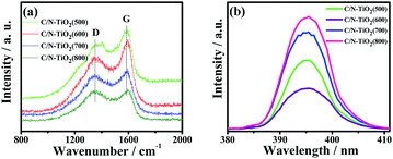
Fig. 5a shows the Raman scattering spectra of C/N-TiO2 hybrid shells. The two characteristic peaks at about 1360 cm−1 (D band) and 1580 cm−1 (G band) for the graphite carbon can be clearly found, indicating the well degree of carbonization from PANI polymer to graphite carbon.16 The D/G intensity ratios for C/N-TiO2 hybrid shells increase with calcination temperature, suggesting increased carbonization degree.
It has been reported that the PL emission can be caused by the recombination of electron–hole pairs of photocatalysts, and the smaller PL intensity suggesting the lower recombination rate of electron–hole pairs.17 Fig. S4† shows the PL spectra of pure TiO2(600) hollow spheres, C-TiO2(600) and C/N-TiO2(600) hybrid shells excited at 360 nm. It can be obviously seen that pure TiO2(600) hollow spheres have a high intensity emission peak at around 395 nm, whereas the intensity decreases for C-TiO2(600) hybrid shells, and weakens a lot for C/N-TiO2(600) hybrid shells. Fig. 5b shows the PL spectra of C/N-TiO2 hybrid shells. It is observed that the PL intensity of C/N-TiO2(600) hybrid shells displays the lowest PL intensity in comparison with others. The results indicate that the recombination of photogenerated electron–hole pairs is effectively suppressed due to the codoping of C and N. The electrically conductive graphite carbon in C-TiO2(600) hybrid shells is beneficial for electron transmission, and the introduction of N in C/N-TiO2 hybrid shells can act as trapping centers for photogenerated electrons which further enhance the separation efficiency of electron–hole pairs.
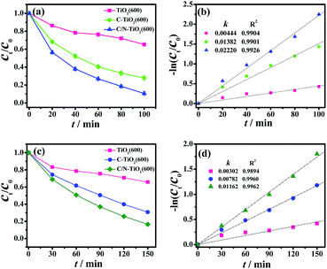
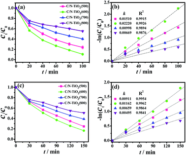
The photocatalytic activities of pure TiO2(600) hollow spheres, C-TiO2(600) and C/N-TiO2 hybrid shells were evaluated by the degradation of organic pollutions RhB and phenol under visible light irradiation. The photocatalytic activity of samples was firstly evaluated by monitoring the degradation of RhB under visible light irradiation. In order to make the as-prepared samples more comparable, the carbon content in C/N-TiO2(600) hybrid shells was maintained similar to that in the C-TiO2(600) hybrid shells by controlling the amount of PANI coating, which was measured by elementary analysis and the results were given in Table S1.† As shown in Fig. 6a and b, the degradation efficiency of RhB reaches 90% and 72% within 100 min for C/N-TiO2(600) and C-TiO2(600) hybrid shells, respectively. However, pure TiO2(600) hollow spheres can convert only about 35%. The apparent reaction rate for C/N-TiO2(600) (k = 0.022 min−1) and C-TiO2(600) hybrid shells (k = 0.014 min−1) are 5.0 and 3.2 times higher than that for pure TiO2(600) hollow spheres (k = 0.0044 min−1), respectively. The photocatalytic results confirm that the incorporation of C and N into TiO2 can significantly enhance their photocatalytic activities. Fig. 7a and b shows the results of RhB degradation using C/N-TiO2 hybrid shells. It is clearly observed that the photocatalytic activity of C/N-TiO2(600) hybrid shells exhibits the best photocatalytic performance. The apparent quantum efficiency for C/N-TiO2(600) hybrid shells photocatalyst is calculated to be 0.89%. The photocatalytic activities of C/N-TiO2(600) hybrid shells are superior to the reported non-metallic element-doped TiO2 hybrids in RhB degradation, as listed in Table S2.†
To further confirm the mineralization of RhB, changes in TOC values of RhB solution using C/N-TiO2(600) hollow hybrids photocatalysts after visible light irradiation were detected (Fig. S5 and Table S3†). It can be seen that TOC removal proceeds much more slowly than the optical color change.18 The decreasing in TOC values of RhB solution indicates that most RhB molecules were degraded into CO2 after visible light irradiation in the presence of C/N-TiO2(600) photocatalysts. As for degradation of phenol under visible light irradiation, C/N-TiO2(600) hybrid shells also exhibited the highest photocatalytic activity as compared with pure TiO2(600) hollow spheres and C-TiO2(600) hybrid shells (Fig. 6c and d), where 84% of phenol was degraded within 150 min (k = 0.012 min−1) with 0.56% apparent quantum efficiency. The photocatalytic activity of C/N-TiO2 hybrid shells for phenol degradation follows the same order as degradation on RhB (Fig. 7c and d). In addition, the recyclability of the C/N-TiO2 hollow hybrids has also been investigated. It can be seen that the photocatalytic activity of C/N-TiO2 hybrid shells towards RhB and phenol degradation under visible light irradiation were slightly decayed after six consecutive runs (Fig. 8), but still had high photocatalytic performance, suggesting their high stability and recyclability.
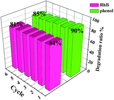 | ||
| Fig. 8 Recyclability of C/N-TiO2(600) hybrid shells as photocatalysts in degradation of RhB and phenol under visible light irradiation. | ||
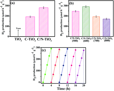
Herein, the C/N-TiO2 hybrid shells were also studied in photocatalytic H2 production under visible light irradiation in methanol aqueous solution. Fig. 9a shows data for a photocatalytic activity comparison of pure TiO2(600) hollow spheres, C-TiO2(600) and C/N-TiO2(600) hybrid shells in H2 production. The highest H2 production activity, as observed for C/N-TiO2(600) hybrid shells, is about 291 μmol h−1 g−1 with 0.9% apparent quantum efficiency. Fig. 9b compares the photocatalytic activity of C/N-TiO2 hybrid shells in H2 production, which follows the same order as degradation on organic pollution. In addition, the activity sequences are the same if the photocatalytic activity is normalized to the specific surface area. The stability of C/N-TiO2(600) hybrid shells in photocatalytic H2 production was also studied, as presented in Fig. 9c. It can be seen that the C/N-TiO2(600) hybrid shells can still exhibit high photocatalytic performance after five cycles. The C/N-TiO2(600) hybrid shells can exhibit the best photocatalytic activity mainly owing to their well-defined hollow structure with high specific surface area, and appropriate anatase-rutile mixed phases.
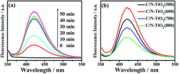
Based on above analysis results, a possible mechanism of photocatalytic reaction under visible light irradiation over C/N-TiO2 hybrid shells was proposed. When the C/N-TiO2 hybrid shells were irradiated under visible light, VB electrons from TiO2 could be excited due to the narrowed band gap of TiO2 coming from C doping. In addition, the incorporation of graphite carbon in TiO2 could facilitate the electron transmission, and the presence of N in C/N-TiO2 hybrid shells could act as trapping centers for electrons. As a result, separation efficiency of electron–hole pairs could be greatly enhanced that leading to improved photocatalytic activity. During the photocatalytic process, the photogenerated electrons on the hybrid shells not only can be trapped by O2, producing oxygen free radicals (˙O2−), but also can reduce H+ ions to produce H2. Meanwhile, the photogenerated holes can react with H2O or hydroxide ions, producing hydroxyl radicals (˙OH). Both oxygen free radicals and hydroxyl radicals are the powerful oxidizing species for organic pollution degradation. The generated ˙OH radicals during the photocatalytic reactions under visible light are detected by using fluorescence method using terephthalic acid as a probe molecule, which can react with ˙OH to produce a fluorescent substance.19 Fig. 10a shows the change of fluorescence spectra with irradiation time under visible light irradiation, indicating ˙OH generation for C/N-TiO2(600) hybrid shells. Fig. 10b shows the comparison of fluorescence intensity for different samples at a fixed time (30 min). As we known, the fluorescence intensity is related to the amount of produced ˙OH. It can be clearly seen that C/N-TiO2(600) hybrid shells show the highest amount of ˙OH radicals. It is further indicating the sample C/N-TiO2(600) has higher photocatalytic activity than other photocatalysts. The above experiments results further confirm that ˙OH radicals are active species in photocatalytic reactions. It has been indicated that the catalytic efficiency of photocatalysts mainly depends on the efficiency utilization of solar energy and the separation efficiency of the electron–hole pairs.20 The codoping of C and N and the incorporated electrically conductive graphite carbon in TiO2 shells are believed to contribute to light absorption and the separation efficiency of the electron–hole pairs, thereby resulting in high photocatalytic performance.
Conclusions
In summary, mesoporous C, N-codoped TiO2 (C/N-TiO2) hybrid shells incorporated with graphite carbon were synthesized, where PANI functioned as both C and N doping sources and supplied the graphite carbon, which can contribute to improve the visible light absorption and photogenerated electron–hole pair separation efficiency of TiO2, and finally lead to enhanced photocatalytic activity. Results showed that C/N-TiO2(600) hybrid shells exhibited the best overall photocatalytic activity in degradation of organic dyes and H2 production under visible light irradiation, which could be attributed to the enhanced visible light absorption and charge separation efficiency associated with the codoped-C and N and the presence of graphite carbon. The strategy provided here will provide a promising route for the construction of other C/N-semiconductor hybrid shells for broader applications.Acknowledgements
The authors gratefully acknowledge financial support from the National Natural Science Foundation of China (21673202 and 21273004), Innovation Program for Graduate Students in Universities of Jiangsu Province (No. KYZZ15_0361), Excellent Doctoral Dissertation of Yangzhou University, Qing Lan Project and the Priority Academic Program Development of Jiangsu Higher Education Institutions. We would also like to acknowledge the technical support received at the Testing Center of Yangzhou University.Notes and references
- (a) J. S. Lee, K. H. You and C. B. Park, Adv. Mater., 2012, 24, 1084–1088 CrossRef CAS PubMed; (b) J. F. Ye, W. Liu, J. G. Cai, S. Chen, X. W. Zhao, H. G. Zhou and L. M. Qi, J. Am. Chem. Soc., 2011, 133, 933–940 CrossRef CAS PubMed; (c) W. G. Tu, Y. Zhou, Q. Liu, Z. P. Tian, J. Gao, X. Y. Chen, H. T. Zhang, J. G. Liu and Z. G. Zou, Adv. Funct. Mater., 2012, 22, 1215–1221 CrossRef CAS; (d) J. B. Joo, Q. Zhang, I. Lee, M. Dahl, F. Zaera and Y. D. Yin, Adv. Funct. Mater., 2012, 22, 166–174 CrossRef CAS; (e) J. Du, X. Y. Lai, N. L. Yang, J. Zhai, D. Kisailus, F. B. Su, D. Wang and L. Jiang, ACS Nano, 2011, 5, 590–596 CrossRef CAS PubMed.
- (a) J. Du, X. Y. Lai, N. L. Yang, J. Zhai, D. Kisailus, F. B. Su, D. Wang and L. Jiang, ACS Nano, 2011, 5, 590–596 CrossRef CAS PubMed; (b) M. A. Henderson and I. Lyubinetsky, Chem. Rev., 2013, 113, 4428–4455 CrossRef CAS PubMed; (c) A. Kudo and Y. Miseki, Chem. Soc. Rev., 2009, 38, 253–278 RSC.
- (a) M. Batzill, Energy Environ. Sci., 2011, 4, 3275–3286 RSC; (b) T. Fröschl, U. Hörmann, P. Kubiak, G. Kučerová, M. Pfanzelt, C. K. Weiss, R. J. Behm, N. Hüsing, U. Kaiser, K. Landfester and M. Wohlfahrt-Mehrens, Chem. Soc. Rev., 2012, 41, 5313–5360 RSC; (c) W. Zhao, W. Ma, C. Chen, J. C. Zhao and Z. Shuai, J. Am. Chem. Soc., 2004, 126, 4782–4873 CrossRef CAS PubMed.
- (a) Q. Zhang, D. Q. Lima, I. Lee, F. Zaera, M. F. Chi and Y. D. Yin, Angew. Chem., Int. Ed., 2011, 50, 7088–7092 CrossRef CAS PubMed; (b) M. M. Khan, S. A. Ansari, M. I. Amal, J. Lee and M. H. Cho, Nanoscale, 2013, 5, 4427–4435 RSC; (c) Z. Wu, Y. Y. Wang, L. Sun, Y. X. Mao, M. Y. Wang and C. J. Lin, J. Mater. Chem. A, 2014, 2, 8223–8229 RSC; (d) M. G. Wang, J. Han, H. X. Xiong, R. Guo and Y. D. Yin, ACS Appl. Mater. Interfaces, 2015, 7, 6909–6918 CrossRef CAS PubMed; (e) M. G. Wang, Y. M. Hu, J. Han, R. Guo, H. X. Xiong and Y. D. Yin, J. Mater. Chem. A, 2015, 3, 20727–20735 RSC; (f) J. S. Lee, K. H. You and C. B. Park, Adv. Mater., 2012, 24, 1084–1088 CrossRef CAS PubMed; (g) B. Rico-Oller, A. Boudjemaa, H. Bahruji, M. Kebir, S. Prashar, K. Bachari, M. Fajardo and S. Gómez-Ruiz, Sci. Total Environ., 2016, 563–564, 921–932 CrossRef CAS PubMed.
- (a) J. H. Park, S. Kim and A. J. Bard, Nano Lett., 2006, 6, 24–28 CrossRef CAS PubMed; (b) X. B. Chen and C. Burda, J. Am. Chem. Soc., 2008, 130, 5018–5019 CrossRef CAS PubMed; (c) J. H. Pan, X. W. Zhang, A. J. H. Du, D. D. Sun and J. O. Leckie, J. Am. Chem. Soc., 2008, 130, 11256–11257 CrossRef CAS PubMed; (d) W. Ho, J. C. Yu and S. Lee, Chem. Commun., 2006, 1115–1117 RSC; (e) R. Asahi, T. Morikawa, T. Ohwaki, K. Aoki and Y. Taga, Science, 2001, 293, 269–271 CrossRef CAS PubMed; (f) S. In, A. Orlov, R. Berg, F. García, S. P. Jimenez, M. S. Tikhov, D. S. Wright and R. M. Lambert, J. Am. Chem. Soc., 2007, 129, 13790–13791 CrossRef CAS PubMed; (g) M. Sathish, B. Viswanathan, R. P. Viswanath and C. S. Gopinath, Chem. Mater., 2005, 17, 6349–6353 CrossRef CAS; (h) H. P. Li, W. Zhang, S. Y. Huang and W. Pan, Nanoscale, 2012, 4, 801–806 RSC; (i) S. Lázaro-Navas, S. Prashar, M. Fajardo and S. GÓmez-Ruiz, J. Nanopart. Res., 2015, 17, 94–105 CrossRef.
- (a) B. C. Qiu, C. C. Zhong, M. Y. Xing and J. L. Zhang, RSC Adv., 2015, 5, 17802–17808 RSC; (b) J. D. Zhuang, Q. F. Tian, H. Zhou, Q. Liu, P. Liu and H. M. Zhong, J. Mater. Chem., 2012, 22, 7036–7042 RSC; (c) G. G. Liu, F. He, J. Zhang, L. J. Li, F. J. Lia, L. X. Chen and Y. Huang, Appl. Catal., B, 2014, 150–151, 515–522 CrossRef CAS.
- (a) S. A. Ansari, M. M. Khan, M. O. Ansari and M. H. Cho, New J. Chem., 2016, 40, 3000–3009 RSC; (b) Z. F. Jiang, X. M. Lv, D. L. Jiang, J. M. Xie and D. J. Mao, J. Mater. Chem. A, 2013, 1, 14963–14972 RSC; (c) D. M. Chen, Z. Y. Jiang, J. Q. Geng, Q. Wang and D. Yang, Ind. Eng. Chem. Res., 2007, 46, 2741–2746 CrossRef CAS.
- (a) R. Silva, D. Voiry, M. Chhowalla and T. Asefa, J. Am. Chem. Soc., 2013, 135, 7823–7826 CrossRef CAS PubMed; (b) W. Ding, L. Li, K. Xiong, Y. Wang, W. Li, Y. Nie, S. Chen, X. Q. Qi and Z. D. Wei, J. Am. Chem. Soc., 2015, 137, 5414–5420 CrossRef CAS PubMed; (c) S. Y. Cao, N. Han, J. Han, Y. M. Hu, L. Fan, C. Q. Zhou and R. Guo, ACS Appl. Mater. Interfaces, 2016, 8, 6040–6050 CrossRef CAS PubMed.
- (a) M. Sathish, B. Viswanathan, R. P. Viswanath and C. S. Gopinath, Chem. Mater., 2005, 17, 6349–6353 CrossRef CAS; (b) Y. Cong, J. J. Zhang, F. Chen and M. Anpo, J. Phys. Chem. C, 2007, 111, 6976–6982 CrossRef CAS; (c) Y. Q. Cao, T. He, Y. M. Chen and Y. A. Cao, J. Phys. Chem. C, 2010, 114, 3627–3633 CrossRef CAS; (d) Y. L. Kuo, T. L. Su, F. C. Kung and T. J. Wu, J. Hazard. Mater., 2011, 190, 938–944 CAS.
- M. G. Wang, J. Han, Y. M. Hu, R. Guo and Y. D. Yin, ACS Appl. Mater. Interfaces, 2016, 8, 29511–29521 CAS.
- (a) J. Q. Shan, Y. X. Liu, P. Liu, Y. S. Huang, Y. Z. Su, D. Q. Wu and X. L. Feng, J. Mater. Chem. A, 2015, 3, 24148–24154 RSC; (b) A. L. M. Reddy, A. Srivastava, S. R. Gowda, H. Gullapalli, M. Dubey and P. M. Ajayan, ACS Nano, 2010, 4, 6337–6342 CrossRef CAS PubMed; (c) L. L. Tian, X. Y. Wei, Q. C. Zhuang, C. H. Jiang, C. Wu, G. Y. Ma, X. Zhao, Z. M. Zong and S. G. Sun, Nanoscale, 2014, 6, 6075–6083 RSC; (d) G. A. Ferrero, K. Preuss, A. Marinovic, A. B. Jorge, N. Mansor, D. J. L. Brett, A. B. Fuertes, M. Sevilla and M. M. Titirici, ACS Nano, 2016, 10, 5922–5932 CrossRef CAS PubMed.
- (a) J. B. Cai, X. Q. Wu, S. X. Li, F. Y. Zheng, L. C. Zhu and Z. H. Lai, ACS Appl. Mater. Interfaces, 2015, 7, 3764–3772 CrossRef CAS PubMed; (b) M. G. Wang, J. Han, H. X. Xiong and R. Guo, Langmuir, 2015, 31, 6220–6228 CrossRef CAS PubMed; (c) M. S. A. S. Shah, A. R. Park, K. Zhang, J. H. Park and P. J. Yoo, ACS Appl. Mater. Interfaces, 2012, 4, 3893–3901 CrossRef PubMed.
- (a) M. Y. Li, Y. Hu, S. L. Xie, Y. C. Huang, Y. X. Tong and X. H. Lu, Chem. Commun., 2014, 50, 4341–4343 RSC; (b) J. Zheng, L. Liu, G. B. Ji, Q. F. Yang, L. R. Zheng and J. Zhang, ACS Appl. Mater. Interfaces, 2016, 8, 20074–20081 CrossRef CAS PubMed.
- (a) S. W. Liu, J. G. Yu and M. Jaroniec, J. Am. Chem. Soc., 2010, 132, 11914–11916 CrossRef CAS PubMed; (b) J. G. Yu and J. R. Ran, Energy Environ. Sci., 2011, 4, 1364–1371 RSC.
- (a) Y. Y. Wen, H. M. Ding and Y. K. Shan, Nanoscale, 2011, 3, 4411–4417 RSC; (b) Y. Wang, J. G. Yu, W. Xiao and Q. Li, J. Mater. Chem. A, 2014, 2, 3847–3855 RSC.
- (a) F. S. Wen, H. Hou, J. Y. Xiang, X. Y. Zhang, Z. B. Su, S. J. Yuan and Z. Y. Liu, Carbon, 2015, 89, 372–377 CrossRef CAS; (b) J. Q. Shan, Y. X. Liu, P. Liu, Y. S. Huang, Y. Z. Su, D. Q. Wu and X. L. Feng, J. Mater. Chem. A, 2015, 3, 24148–24154 RSC.
- (a) M. Q. Yang, B. Weng and Y. J. Xu, Langmuir, 2013, 29, 10549–10558 CrossRef CAS PubMed; (b) N. Zhang, Y. Zhang, X. Pan, M. Q. Yang and Y. J. Xu, J. Phys. Chem. C, 2012, 116, 18023–18031 CrossRef CAS; (c) L. Jing, Z. Y. Ynag, Y. F. Zhao, X. Guo, Y. M. Yan and K. N. Sun, J. Mater. Chem. A, 2014, 2, 1068–1075 RSC; (d) N. Zhang, Y. H. Zhang, X. Y. Pan, X. Z. Fu, S. Q. Liu and Y. J. Xu, J. Phys. Chem. C, 2011, 115, 23501–23511 CrossRef CAS.
- (a) J. Fernandez, J. Bandara, A. Lopez, P. Buffat and J. Kiwi, Langmuir, 1999, 15, 185–192 CrossRef CAS; (b) J. G. Yu, G. P. Dai and B. B. Huang, J. Phys. Chem. C, 2009, 113, 16394–16401 CrossRef CAS.
- (a) K. Ishibashi, A. Fujishima, T. Watanabe and K. Hashimoto, Electrochem. Commun., 2000, 2, 207–210 CrossRef CAS; (b) Q. Xiao, Z. C. Si, J. Zhang, C. Xiao and X. K. Tan, J. Hazard. Mater., 2008, 150, 62–67 CrossRef CAS PubMed; (c) J. G. Yu, W. G. Wang, B. Cheng and B. L. Su, J. Phys. Chem. C, 2009, 113, 6743–6750 CrossRef CAS.
- (a) Y. Y. Wen, H. M. Ding and Y. K. Shan, Nanoscale, 2011, 3, 4411–4417 RSC; (b) Q. Zhang, D. Q. Lima, I. Lee, F. Zaera, M. F. Chi and Y. D. Yin, Angew. Chem., Int. Ed., 2011, 50, 7088–7092 CrossRef CAS PubMed; (c) X. Li, X. Chen, H. Niu, X. Han, T. Zhang, J. Y. Liu, H. M. Lin and F. Y. Qu, J. Colloid Interface Sci., 2015, 452, 89–97 CrossRef CAS PubMed; (d) Z. Wu, Y. Y. Wang, L. Sun, Y. X. Mao, M. Y. Wang and C. J. Lin, J. Mater. Chem. A, 2014, 2, 8223–8229 RSC.
Footnote |
| † Electronic supplementary information (ESI) available: Additional TEM, XPS, fluorescence spectra and photocatalytic results towards RhB degradation of C/N-TiO2 photocatalysts. See DOI: 10.1039/c7ra00985b |
| This journal is © The Royal Society of Chemistry 2017 |


