
 Open Access Article
 This Open Access Article is licensed under a Creative Commons Attribution-Non Commercial 3.0 Unported Licence
Hierarchical porous MnO/graphene composite aerogel as high-performance anode material for lithium ion batteries†
Zhiying Ma‡
ac,
Hailiang Cao‡ab,
Xufeng Zhou a,
Wei Dengac and
Zhaoping Liu*a
a,
Wei Dengac and
Zhaoping Liu*a
aKey Laboratory of Graphene Technologies and Applications of Zhejiang Province, Advanced Li-ion Battery Engineering Lab, Ningbo Institute of Materials Technology and Engineering, Chinese Academy of Sciences, Zhejiang 315201, P. R. China. E-mail: liuzp@nimte.ac.cn; zhouxf@nimte.ac.cn; Fax: +86-574-8668-5096; Tel: +86-574-8668-5096
bKey Laboratory of Interface Science and Engineering in Advanced Materials of Ministry of Education, Taiyuan University of Technology, Shanxi 030024, China
cUniversity of Chinese Academy of Sciences, 19 A Yuquan Rd, Shijingshan District, Beijing, P. R. China 100049
First published on 10th March 2017
Abstract
MnO is a promising anode material for lithium-ion batteries due to its high theoretical capacity and low conversion potential, but it exhibits poor electrical conductivity and volume expansion and hence its practical application is hindered. In this work, we describe a high-conductive and low-expansion MnO/porous-graphene aerogel (MnO/PGA) hybrid with hierarchical pore structure, which was synthesized by a novel site-localized nanoparticle-induced etching strategy. While graphene network intrinsically guarantees fast electron transfer, it is the characteristic presence of nanosized pores on the graphene sheets that lead to high reversible capacity, favorable rate capability and cycling stability by (i) facilitating the electrolyte infiltration and shortening the diffusion distances of Li-ions, (ii) providing more defects on the graphene sheets to increase the lithium-storage active sites. As a result, the MnO/PGA hybrid exhibits a reversible electrochemical lithium storage capacity as high as 979.6 mA h g−1 at 0.5 A g−1 after 300 cycles and excellent rate capability of delivering 493.6 mA h g−1 at a high current density of 2 A g−1.
Introduction
In the past years, Li-ion batteries (LIBs) have been widely used in portable electronics due to their high energy density, low maintenance and relatively low self-discharge. However they are still far from satisfying the demand of large energy storage equipment such as electric vehicles and smart grid applications, owing to the unsatisfying energy density of LIBs. The prevailing commercial anode material, graphite, only possesses a theoretical capacity of 372 mA h g−1, which is a bottleneck for developing new generation LIBs. Recently, manganese oxides (MnOX) have been intensively exploited as alternative anode materials because of their high theoretical specific capacity, high density, low cost, environment benignity and high abundance of Mn.1–5 Among them, MnO is viewed as a better anode material due to a lower conversion potential and little voltage hysteresis.6–11 Nevertheless, the practical application of MnO anode material is hampered because of its poor electrical conductivity and drastic volume variation during the cycling processes, which results in poor rate performance and inferior cycle stability.To overcome these problems, a suitable matrix is highly desirable to increase the electrical conductivity and buffer the volume change of MnO. In this respect, graphene is an excellent candidate because of its exceptional electrical and mechanical properties, large specific surface area and chemical stability. To date, several preliminary researches about MnO/graphene composite anode materials have been reported.12–19 Among these studies, the sandwich structure in which flexible graphene sheets anchored with transition metal oxides form layered structure is favored by many researchers.11,15–21 For example, Song et al. synthesized MnO-nanowire/graphene composite with a sandwich-like structure and reported a reversible lithium storage capacity of 930 mA h g−1 after 500 cycles at 0.5 A g−1.15 Zhang and coworkers reported a reversible lithium storage capacity as high as 772 mA h g−1 at 100 mA g−1 after 90 cycles for a nitrogen-doped MnO/graphene hybrid with a similar sandwich structure.11 Even though the MnO/graphene composites with different sandwich-like structures have shown a good prospect in high-capacity LIBs, their disadvantages in Li-ion storage cannot be neglected. For example, the closely packed architecture would hinder the electrolyte infiltration, intrinsically limiting mass transfer. Furthermore, MnO particles distributed on the graphene layers are likely to increase the contact resistance between graphene nanosheets, which would limit the fast electron transfer as well as aggravate the polarization of electrode at high current densities. Therefore, the design of MnO/graphene composite with novel nanostructure is necessary to solve these defects.
In recent years, assembly of 2D graphene sheets into 3D architecture has obtained researchers' favor due to the excellent mechanical, electrical and thermal properties of 3D porous grapheme.22–27 But the large graphene sheets may increase the transport distance of Li-ions inside the active materials. Therefore some researchers have attempted to create nanoholes on the graphene sheets to address this issue.28–34 For example, Fan et al. synthesized porous graphene nanosheets (PGs) using the etching strategy, which showed excellent rate capability due to its open layered and mesoporous structure that facilitated efficient access of electrolytes to the electrode material and shortened the ion diffusion pathway through the porous sheets.32 Our group has also successfully fabricated 3D monolithic PG/Co hybrid aerogel with high gravimetric/volumetric capacity as a compressible anode for LIBs and site-localized nanoparticle-induced etching strategy was proposed for the formation of nanopores on graphene sheets.34 Therefore, PG sheets as building blocks for construction of large-scale 3D frameworks with hierarchical pore distributions provide a unique platform for design and development of novel composite anode materials. Specifically for MnO, the PG network allows fast mass transport through their hierarchically arranged pores and provides three dimensional electron transport pathways. In addition, the open porous structure of PG network can offer abundant space to buffer volume expansion of MnO during charge and discharge processes. To the best of our knowledge, there have been no reports of the controllable assembly of MnO nanoparticles supported on 3D PG networks as anode materials.
In this work, monolithic MnO/porous-graphene aerogel (MnO/PGA) composite anode material was fabricated via a combined process of hydrothermal self-assembly, freeze-drying and annealing. During annealing, uniform MnO nanoparticles and nanopores on the graphene were simultaneously generated through a site-localized nanoparticle-induced etching strategy.34 In contrast to previous reports on graphene-supported composites with sandwich structure, MnO/PGA composites demonstrate 3D interconnected macroporous architecture with uniform deposition of MnO nanoparticles and distribution of nanopores (50–100 nm), which provides highly conductive networks with enhanced surface area and short diffusion lengths for lithium ions. As a result, MnO/PGA exhibits outstanding reversible capacity and excellent rate performance (979.6 mA h g−1 after 300 cycles at a charge–discharge rate of 0.5 A g−1 and reversible discharge capacity of 493 mA h g−1 at 2 A g−1), when employed as the anode material for LIBs.
Experimental
Materials preparation
Graphite oxide was synthesized from natural graphite flakes (50 μm) following a modified Hummers method.35 To prepare the graphene oxide (GO) solution, the obtained graphite oxide was dispersed in water by sonication for 15 min, reaching a concentration of 2 mg mL−1. 30 mL of homogeneous GO aqueous dispersion was sealed in a cylindrical vessel and maintained at 180 °C for 12 h. Then the autoclave was naturally cooled to room temperature. The resulting graphene hydrogel was immersed in Mn(NO3)2 solution (50 mg mL−1) for 6 h to absorb the Mn2+ adequately via electrostatic interaction. Then the hydrogel was taken out and directly dehydrated via a freeze-drying process to maintain the 3D monolithic architecture. Finally, the MnO/PGA composite was fabricated by annealing the dehydrated aerogel at 850 °C for 2 h in Ar atmosphere.For comparison, bare graphene aerogel (GA) was also prepared by annealing the raw graphene oxide aerogel in the same condition. The pure MnO was obtained by annealing the Mn(CH3COO)2 particles directly at 850 °C for 2 h. And MnO/graphene aerogel (MnO/GA) composite with no nanoholes on graphene sheets was prepared by the similar procedure in which the graphene hydrogel was immersed in the Mn(CH3COO)2 solution.
Materials characterization
Powder X-ray diffraction (XRD) patterns were recorded on a D8 X-ray diffractometer using Cu-Kα irradiation (λ = 1.5406 Å) at 40 kV, 20 mA over the 2θ range from 10 to 80°. The microstructure of the samples was characterized by field-emission scanning electron microscope (SEM, FEI, Sirion 200) and transmission electron microscope (TEM, JEOL 2100F). Thermogravimetric and differential thermal analyses (TG/DTA) were performed with a PerkinElmer Diamond TG/DTA apparatus at a heating rate of 10 °C min−1 in flowing air. Raman spectra were measured on a Renishaw Invia spectrometer using a laser of 514.5 nm at room temperature. Nitrogen adsorption–desorption isotherms were recorded at 77 K using a Micrometritics ASAP 2020 analyzer.Electrochemical measurements
For preparing working electrodes, a mixture of active material (80 wt%), polyvinylidene difluoride (binder, 10 wt%) and super P (10 wt%) dispersed in N-methyl-2-pyrrolidinone (NMP) was coated on the nickel-foam (ca. 1.3 cm2) and dried at 80 °C in vacuum for 6 h before pressing. The mass of the active component for each plate was about 2–3 mg. The electrochemical performance of the active material was evaluated via CR2032 type coin cells with a pure lithium foil as the counter electrode, Celgard 2300 as the separator, and 1 M LiPF6 in a mixture of ethylene carbonate (EC) and dimethyl carbonate (DMC) (v/v = 1![[thin space (1/6-em)]](https://www.rsc.org/images/entities/char_2009.gif) :1) as the electrolyte. The cells were assembled in an argon-filled glove box with concentrations of moisture and oxygen below 1.0 ppm. After assembling, the cells were charged and discharged in Land CT 2001A system at various current densities in the voltage range of 0.01 to 3.0 V. Cyclic voltammograms (CV) were measured on a Solartron 1400 workstation with the testing voltage between 0.01 and 3.0 V at a scan rate of 0.1 mV s−1. The electrochemical impedances spectroscopy (EIS) of active material was recorded on an electrochemical workstation (Solartron 1400) using the frequency response analysis. The impedance spectra were obtained by applying a sine wave with amplitude of 5.0 mV over the frequency range from 100 kHz to 0.01 Hz.
:1) as the electrolyte. The cells were assembled in an argon-filled glove box with concentrations of moisture and oxygen below 1.0 ppm. After assembling, the cells were charged and discharged in Land CT 2001A system at various current densities in the voltage range of 0.01 to 3.0 V. Cyclic voltammograms (CV) were measured on a Solartron 1400 workstation with the testing voltage between 0.01 and 3.0 V at a scan rate of 0.1 mV s−1. The electrochemical impedances spectroscopy (EIS) of active material was recorded on an electrochemical workstation (Solartron 1400) using the frequency response analysis. The impedance spectra were obtained by applying a sine wave with amplitude of 5.0 mV over the frequency range from 100 kHz to 0.01 Hz.
Results and discussion
Materials synthesis and characterization
The synthetic route of MnO/PGA is illustrated in Fig. 1. First, GO sheets were self-assembled into a 3D hydrogel via a hydrothermal method. Second, the hydrogel was immersed in Mn(NO3)2 solution for 6 h, during which Mn2+ ions diffused into the hydrogel due to the concentration difference and were attracted to the surface of graphene sheets via electrostatic interaction. Third, the graphene hydrogel attached with Mn2+ was directly dehydrated via a freeze-drying process to maintain the 3D monolithic architecture. Then the as-obtained aerogel is heat treated at a high temperature of 850 °C for 2 h under Ar atmosphere to synthesize the MnO/PGA hybrid. During the annealing process, Mn(NO3)2 was initially transformed to Mn3O4, which then reacted with carbon atoms in graphene to form MnO nanocrystals and generate nano-sized holes on the graphene sheets simultaneously, following the reaction equation of Mn3O4 + C → MnO + CO.19 For comparison, MnO/GA hybrid without pores on graphene sheets was also prepared by using Mn(CH3COO)2 as the precursor instead of Mn(NO3)2, as Mn(CH3COO)2 decomposed into MnO directly during annealing.16 Bare MnO and bare GA were also synthesized for comparison.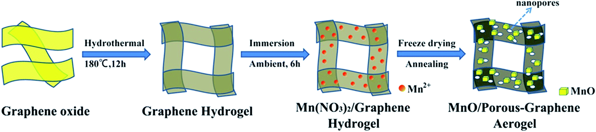 | ||
| Fig. 1 Schematic illustration of the synthesis route of MnO/PGA. | ||
XRD patterns of the MnO/PGA, MnO/GA and pure MnO are shown in Fig. 2a. The characteristic peaks of the bare MnO can be indexed to a cubic phase MnO (JCPDS no.78-0230).15,16 All strong peaks of the MnO/PGA and MnO/GA hybrid materials are consistent with the bare MnO and a weak peak at around 26° is in accordance with the characteristic peak of the (002) plane of graphene. As we can see from the XRD patterns, MnO/GA and MnO/PGA hybrids own the same components even though their precursors are different before annealing. However the peak intensity of MnO phase in MnO/PGA sample is weaker than that in MnO/GA and the full width of peaks at half-maximum in MnO/PGA becomes broader comparing with that in MnO/GA. The difference is caused by the size variation of MnO particles on graphene sheets when using different manganese precursors, which will be further confirmed later by other analysis methods. TGA measurement carried out in the air is used to determine the content of MnO in MnO/PGA and MnO/GA hybrid. As shown in Fig. 2b, the two TGA curves are similar, both of which display a slight weight increase from 200 °C to 400 °C, corresponding to oxidation of MnO to Mn2O3 in air. Then a significant weight loss from 400 °C to 500 °C occurs, which is contributed by the combustion of graphene. The weight of both samples becomes steady above 500 °C, suggesting that only thermally stable Mn2O3 remains.15,16,18 Hence the weight proportions of MnO in two hybrids are calculated to be 56.4% (MnO/GA) and 59.1% (MnO/PGA), respectively.
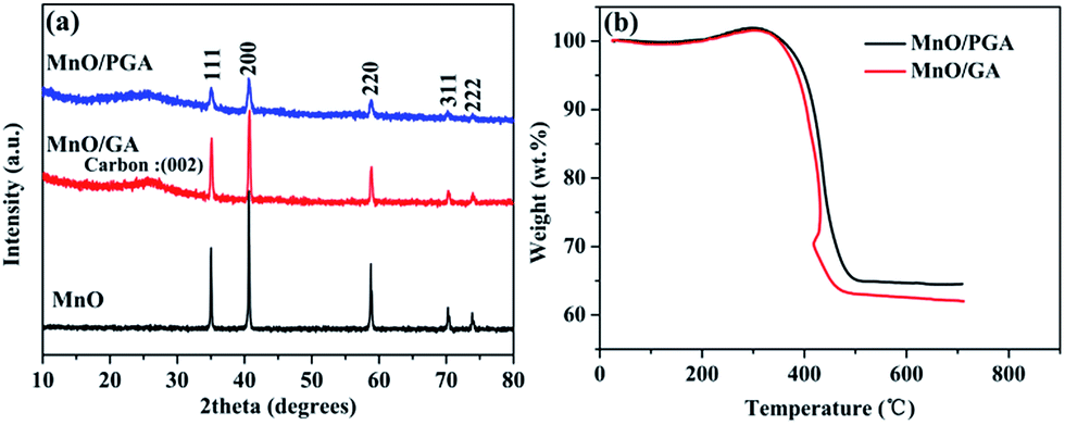 | ||
| Fig. 2 (a) XRD patterns of MnO/PGA, MnO/GA and MnO samples. (b) TGA curves of MnO/PGA and MnO/GA samples. | ||
The morphology and microstructure of MnO/PGA hybrid were investigated by field-emission scanning electron microscopy (FE-SEM) and transmission electron microscopy (TEM). As shown in Fig. 3a, the MnO/PGA hybrid maintains an integrated 3D network with continuous pores of several micrometers, which is similar to typical bare GA. Furthermore in the SEM image of MnO/PGA with higher magnification (Fig. 3b), it can be seen that the MnO particles, which are around 50–100 nm in size, are anchored on the graphene sheets uniformly, and some holes are also obvious around these nanoparticles. Fig. 3c exhibits a TEM image for the MnO/PGA sample. Cubic MnO nanoparticles are well attached to the wrinkled porous graphene sheets and the nanopores keep a similar morphology as MnO particles, which further verifies the etching mechanism. After removing MnO nanoparticles by HCl, a large amount of nanoholes homogenously distributing on the thin graphene layers are clearly seen (Fig. 3d). These results indicate that MnO/PGA hybrid can be effectively produced by site-localized nanoparticle-induced etching strategy at proper annealing condition.
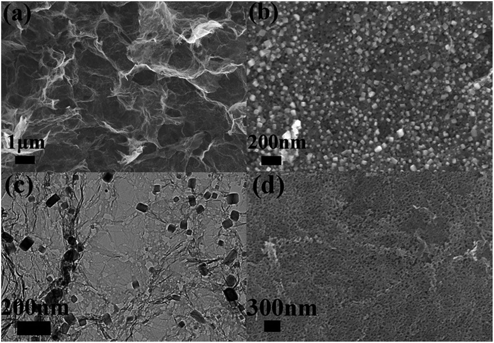 | ||
| Fig. 3 (a and b) Typical SEM images with different magnifications of MnO/PGA hybrid. (c) TEM image of MnO/PGA composite. (d) SEM image of the residue of MnO/PGA after washing with HCl. | ||
For comparison, bare MnO and MnO/GA composite were also prepared by the similar procedure. Fig. 4a shows that bare MnO particles prepared by direct thermal decomposition of Mn(CH3COO)2 have sizes around several hundreds of nanometers. Moreover, the agglomeration is severe among MnO particles. Fig. 4b displays the SEM image of MnO/GA hybrid in which MnO particles ranging from 150 to 200 nm distribute on the graphene sheets, and graphene sheets form a 3D network. As we can see that the sizes of MnO particles have a remarkable decrease with the introduction of graphene sheets comparing to bare MnO. The same phenomenon can also be observed in other reports.5–11 However MnO particles in MnO/PGA hybrid have the smallest size among three samples, which should be ascribed to the site-localized nanoparticle-induced etching strategy. Moreover, no nanopores around MnO particles can be found in the SEM (Fig. 4c) and TEM images (Fig. 4d) of MnO/GA composite. This is because during annealing, Mn(CH3COO)2 decomposes to MnO directly at low temperature, and MnO is inert in Ar atmosphere, which can't react with carbon at high temperature.8,16
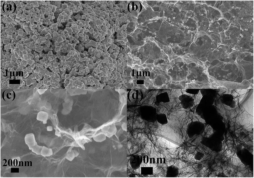 | ||
| Fig. 4 (a) Typical SEM image of bare MnO. (b and c) SEM images with different magnifications of MnO/GA composite. (d) TEM image of MnO/GA composite. | ||
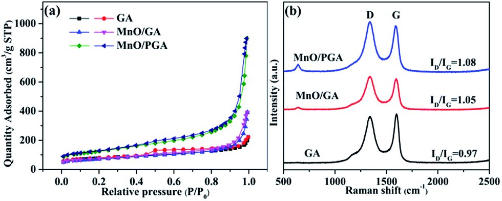
The nitrogen adsorption/desorption study was used to test the GA, MnO/GA and MnO/PGA. The specific surface area of MnO/PGA is 439.3 m2 g−1, which is much higher than that of pristine GA (271.53 m2 g−1). The specific surface area of MnO/GA (249.8 m2 g−1) is similar to that of pristine GA (271.53 m2 g−1), which suggests that the enlarged surface area of MnO/PGA is mainly induced by the nanopores on the graphene sheets. The pore size distribution of three sampels (Fig. S1†) were also estimated by BJH method. Comparing with bare GA, the existence of macropores (ca. 50–70 nm) for MnO/PGA also confirms the formation of nanopores on graphene by etching. The Raman spectra (Fig. 5b) were also recorded to investigate the structure changes from GA to MnO/PGA. The high intensity of the D band indicates the presence of defects in the MnO/PGA hybrid. The intensity ratio of the D band to the G band (ID/IG) of the MnO/PGA is 1.08, whereas 0.97 and 1.05 for GA and MnO/GA, respectively. For MnO/PGA, the high ID/IG value may be ascribed to more defects due to the nanopores in the graphene sheets, which is in good agreement with SEM and TEM results.
 | ||
| Fig. 5 (a) Nitrogen adsorption/desorption isotherms (b) Raman spectra of GA, MnO/GA and MnO/PGA samples. | ||
Electrochemical performance
To understand the electrochemical performance of the MnO/PGA composite as anode material for LIBs, the cyclic voltammetry (CV) curves for the initial three cycles were tested at a scan rate of 0.1 mV s−1 in the voltage range of 0.01–3 V. In the first cycle, an irreversible reduction peak at around 0.6 V corresponds to the formation of a solid electrolyte interface (SEI) layer, and the weak peak located at ca. 1.5–1.2 V may be attributed to the reduction of the electrolyte. The large reduction peak at about 0.2 V in the first cycle can be ascribed to the complete reduction of Mn2+ to Mn0. And the reduction peak of Mn2+ to Mn0 is shifted to ca. 0.50 V in the subsequent cycles due to the improved kinetics of the MnO/PGA electrode after first lithiation. The main anodic peak is located at ca. 1.20 V, corresponding to the oxidation of Mn0 to Mn2+, and the weak and broad peak at around 2.10 V is associated with the oxidation of Mn2+ to a higher oxidation state.16 Importantly, after the first cycle, the subsequent CV curves are almost overlapped, proving that a stable SEI layer is generated on the surface of the hybrid and the structural integrity of the small MnO particles is maintained, thereby leading to excellent reversibility of the MnO/PGA electrode.Fig. 6b presents the first discharge and charge curves of bare MnO, MnO/GA, and MnO/PGA at 50 mA g−1 within a cut-off voltage window between 0.01 and 3 V. In the first cycle, bare MnO anode shows an initial reversible specific capacity of 623 mA h g−1 with a coulombic efficiency (CE) of 66.8%, which coincides with the related reports.5,18 The capacity loss is mainly attributed two points. Much of irreversible Li+ is consumed to form the SEI layer and the poor electrical conductivity of bare MnO also hampers the conversion from Li2O to Li+ in the first charge process, resulting in low initial reversible capacity releasing. At the same current density, MnO/GA reveals a reversible capacity of 684.7 mA h g−1 with a low CE of 49.8%, whereas MnO/PGA delivers a specific discharge capacity of 1421.4 mA h g−1 and charge capacity of 804.6 mA h g−1 with a relatively higher CE of 56.6%. The increased capacity of two hybrids compared with bare MnO may be attributed to the graphene sheets which can accelerate the electron transfer in electrode. However the lower CE of two hybrids is also because of the graphene sheets, which is an inherent phenomenon for carbon materials with large surface area. By contrast, MnO/PGA displays a better electrochemical performance than MnO/GA. This should be ascribed to the advantages of MnO/PGA hybrid as following: (i) the hierarchical porous structure which makes the electrolyte infiltrate into monolithic electrode adequately and provides more active sites and edges for faster electron transport, guarantees that the electrochemical activity of MnO could be exploited availably during the first cycle; (ii) the lithium-storage active sites of graphene sheets increase due to more defects generated by nanopores, leading to higher reversible capacity obtained than pristine graphene. And it was found that the charge curves of MnO/GA and MnO/PGA hybrids begin to diverge above 0.5 V, which implies that the increased capacity are partly from the defects, such as pores or the edge sites of grapheme;36 (iii) the sizes of MnO particles (50–100 nm) are smaller than those in the MnO/GA hybrid (150–200 nm), which enhances the electrochemical activity of MnO particles owing to their higher specific surface area.
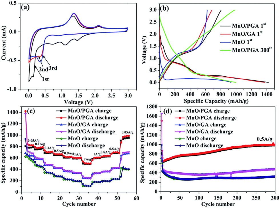 | ||
| Fig. 6 (a) CV profiles of the MnO/PGA sample. (b) The initial charge–discharge profiles of different samples (MnO/PGA, MnO/GA and bare MnO) at 0.05 A g−1, the 300th cycle of MnO/PGA at 0.5 A g−1. (c) Rate capability of different samples. (d) Cycle performance of different samples at 0.5 A g−1. | ||
The rate performance of electrode materials is a very important parameter for their applications. As shown in Fig. 6c, the MnO/PGA presents evidently higher capacity than bare MnO or MnO/GA electrode under all investigated current densities (0.05–2 A g−1). Based on the initial charge capacity at 0.05 A g−1, the capacity retention of MnO/PGA, MnO/GA and MnO electrodes at 2 A g−1 is calculated to be 61.3%, 35.3% and 17%, respectively. The charge–discharge curves (Fig. S2†) demonstrate slow decay of the reversible capacity and slow decline of the voltage plateau of MnO/PGA with the increase of the current, also suggesting good rate capability. As far as we know, such excellent rate performance has barely been achieved in previous studies of MnO/graphene composites, which should be largely ascribed to the PG network with hierarchical pore structure. Not only could the 3D interconnected GA substrate facilitate the electrolyte infiltration and the transfer of ions and charges, but also the nanopores on the graphene sheets provide abundant pathways for the fast Li-ion transport under high current densities. Furthermore, the sizes of MnO are controlled in a small dimension in the MnO/PGA sample via a site-localized nanoparticle-induced etching strategy, which generates more exposed active sites to achieve rapid charge and discharge of MnO/PGA. It is worth noting that when the current density is changed back to 0.05 A g−1, the reversible capacity of MnO/PGA rises to 876 mA h g−1, which is even higher than the initial capacity (804.6 mA h g−1), demonstrating that the 3D PG network can maintain structure integrity of the electrode.
In addition to the rate performance, the cycle performance is also measured to determine the structure stability of samples during cycling (Fig. 6d). MnO/PGA displays an initial reversible capacity of 635.5 mA h g−1 at 0.5 A g−1, then the specific capacity has a slight decline from 635.5 mA h g−1 to 630 mA h g−1 in the next 10 cycles. Surprisingly, the gravimetric capacity rises to 979.6 mA h g−1 after subsequent 290 cycles, which is even higher than the theoretical capacity of MnO (755 mA h g−1). Similar results have been reported for many other MnO/graphene composite anodes.15,16,37–39 It has been confirmed that Mn2+ ions could be further oxidized to a higher oxidation state in well-designed MnO/graphene composites.16 By investigating the charge–discharge curves of MnO/PGA electrode at different cycle numbers (Fig. S3†), it is found that the charge curves before ca. 1.5 V at different cycles almost overlap, while the curves after 1.5 V gradually flatten and elongate to higher specific capacities along with cycling, indicating an ever-increasing capacity and Li+ reactivity. An obvious charge plateau at around 2.10 V can be clearly observed after the 200th cycle, implying a higher oxidation state (>2) of manganese in the end product.38 For the MnO/PGA composite, the 3D graphene network intrinsically guarantees fast electron transfer, and the nanopores on the graphene sheets facilitate the electrolyte infiltration and shorten the diffusion distances of Li-ions, both of which are beneficial for the improvement of the reaction kinetics between MnO and Li+, resulting that much higher state of Mn is obtained gradually during cycling. Thus, it is reasonable that Mn2+ ions in the MnO/PGA electrode can be oxidized to a higher oxidation state during long-term cycling, resulting in gradual increase of the specific capacity. Nevertheless, this phenomenon was not found in the charge curve of bare MnO and it displays poor cyclability with low capacity. Actually, the cycling curve of MnO/GA shows a similar tendency as MnO/PGA but it goes through a longer declining process than MnO/PGA. It is probably because the MnO particles on the graphene sheets are pulverized and dissolved into the electrolyte during the first 150 cycles, leading to the decline of the specific capacity. After following 150 cycles, the reversible capacity of MnO/GA increases to 475.8 mA h g−1 gradually, indicating that the MnO particles are controlled within a reasonable size. To further confirm the structural integrity of MnO/PGA hybrid, its morphology (Fig. S4†) after continuous cycles was studied. The 3D porous graphene network is well preserved after 50 cycles at 0.05 A g−1, and the nanopores on the graphene sheets can also be detected obviously. Meanwhile, MnO nanoparticles are still uniformly attached to the graphene sheets, and their particle sizes remains almost the same as the ones before cycling. These results indicate that the structural integrity of MnO/PGA electrode can be well maintained during cycling, thereby leading to excellent cycling stability.
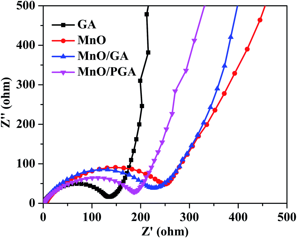
To verify the superior electrochemical performance of 3D MnO/PGA electrode, AC impedance measurements are carried out in the initial cycle, and the results are displayed in Fig. 7. As we can see, the diameter of the semicircle for MnO/PGA in the high-medium frequency region is much smaller than that of MnO/GA, suggesting that MnO/PGA possesses lower contact and charge transfer resistance. Furthermore, it can be concluded that the diffusion impedance of lithium ions in the MnO/PGA electrode is lower than other electrodes from the low-frequency linear part, indicating that the nanopores on the graphene sheets provide abundant pathways for the lithium ions transfer, which validates our results further.
 | ||
| Fig. 7 EIS spectra of the pristine GA, bare MnO, MnO/GA and MnO/PGA hybrid. | ||
Conclusions
A promising MnO/PGA hybrid anode material having hierarchical pore structure was synthesized by a novel site-localized nanoparticle-induced etching strategy. The high capacity, good cycling stability and excellent rate capability of MnO/PGA can be attributed to synergistic interactions between MnO particles and PGA. First, small MnO particles on the graphene sheets ranging from 50 to 100 nm are obtained through a site-localized nanoparticle-induced etching strategy. Second, the 3D conductive network composed of porous-graphene sheets can not only serve as multidimensional pathways to facilitate the transport of electrons and ions in the bulk electrode, but also provide abundant lithium-storage active sites due to more defects generated. Third, the space held up by 3D graphene framework and the nanopores on the graphene sheets relieve the inner stress caused by dramatic volume change of MnO during Li+ insertion/extraction, leading to a long cycle lifetime. In conclusion, the combination of PG sheets and the 3D network framework play an unparalleled role to inspire the potential of MnO as a better anode material, which provide an effective approach to achieve superior lithium-storage properties.Acknowledgements
This work was financially supported by the National Natural Science Foundation of China (Grant no. 21371176) and Key Research Program of the Chinese Academy of Sciences (Grant no. KGZD-EW-T08).Notes and references
- G. Yang, Y. Li, H. Ji, H. Wang, P. Gao, L. Wang, H. Liu, J. Pinto and X. Jiang, J. Power Sources, 2012, 216, 353–362 CrossRef CAS.
- Y. Qiu, G.-L. Xu, K. Yan, H. Sun, J. Xiao, S. Yang, S.-G. Sun, L. Jin and H. Deng, J. Mater. Chem., 2011, 21, 6346–6353 RSC.
- S.-Y. Liu, J. Xie, Y.-X. Zheng, G.-S. Cao, T.-J. Zhu and X.-B. Zhao, Electrochim. Acta, 2012, 66, 271–278 CrossRef CAS.
- Y. Li, Q. Zhang, J. Zhu, X.-L. Wei and P. K. Shen, J. Mater. Chem. A, 2014, 2, 3163–3168 CAS.
- K. Zhong, B. Zhang, S. Luo, W. Wen, H. Li, X. Huang and L. Chen, J. Power Sources, 2011, 196, 6802–6808 CrossRef CAS.
- C.-T. Hsieh, C.-Y. Lin and J.-Y. Lin, Electrochim. Acta, 2011, 56, 8861–8867 CrossRef CAS.
- S. M. Lee, S. H. Choi, J.-K. Lee and Y. C. Kang, Electrochim. Acta, 2014, 132, 441–447 CrossRef CAS.
- J. Zang, H. Qian, Z. Wei, Y. Cao, M. Zheng and Q. Dong, Electrochim. Acta, 2014, 118, 112–117 CrossRef CAS.
- T. Wu, F. Tu, S. Liu, S. Zhuang, G. Jin and C. Pan, J. Mater. Sci., 2013, 49, 1861–1867 CrossRef.
- G. Zhao, X. Huang, X. Wang, P. Connor, J. Li, S. Zhang and J. T. S. Irvine, J. Mater. Chem. A, 2015, 3, 297–303 CAS.
- K. Zhang, P. Han, L. Gu, L. Zhang, Z. Liu, Q. Kong, C. Zhang, S. Dong, Z. Zhang, J. Yao, H. Xu, G. Cui and L. Chen, ACS Appl. Mater. Interfaces, 2012, 4, 658–664 CAS.
- Y. Sun, Q. Wu and G. Shi, Energy Environ. Sci., 2011, 4, 1113–1132 CAS.
- S. Guo and S. Dong, Chem. Soc. Rev., 2011, 40, 2644–2672 RSC.
- C. Xu, B. Xu, Y. Gu, Z. Xiong, J. Sun and X. S. Zhao, Energy Environ. Sci., 2013, 6, 1388–1414 CAS.
- S. Zhang, L. Zhu, H. Song, X. Chen and J. Zhou, Nano Energy, 2014, 10, 172–180 CrossRef CAS.
- Y. Sun, X. Hu, W. Luo, F. Xia and Y. Huang, Adv. Funct. Mater., 2013, 23, 2436–2444 CrossRef CAS.
- A. Yu, H. W. Park, A. Davies, D. C. Higgins, Z. Chen and X. Xiao, J. Phys. Chem. Lett., 2011, 2, 1855–1860 CrossRef CAS.
- Y. J. Mai, D. Zhang, Y. Q. Qiao, C. D. Gu, X. L. Wang and J. P. Tu, J. Power Sources, 2012, 216, 201–207 CrossRef CAS.
- D. Qiu, L. Ma, M. Zheng, Z. Lin, B. Zhao, Z. Wen, Z. Hu, L. Pu and Y. Shi, Mater. Lett., 2012, 84, 9–12 CrossRef CAS.
- M. Zheng, D. Qiu, B. Zhao, L. Ma, X. Wang, Z. Lin, L. Pan, Y. Zheng and Y. Shi, RSC Adv., 2013, 3, 699–703 RSC.
- Z. Jian, B. Zhao, P. Liu, F. Li, M. Zheng, M. Chen, Y. Shi and H. Zhou, Chem. Commun., 2014, 50, 1215–1217 RSC.
- Y. Xu, K. Sheng, C. Li and G. Shi, ACS Nano, 2010, 4324–4330 CrossRef CAS PubMed.
- B. Qiu, M. Xing and J. Zhang, J. Am. Chem. Soc., 2014, 136, 5852–5855 CrossRef CAS PubMed.
- W. Lv, C. Zhang, Z. Li and Q. H. Yang, J. Phys. Chem. Lett., 2015, 6, 658–668 CrossRef CAS PubMed.
- H.-K. Kim, S.-H. Park, S.-B. Yoon, C.-W. Lee, J. H. Jeong, K. C. Roh and K.-B. Kim, Chem. Mater., 2014, 26, 4838–4843 CrossRef CAS.
- L. Xiao, D. Wu, S. Han, Y. Huang, S. Li, M. He, F. Zhang and X. Feng, ACS Appl. Mater. Interfaces, 2013, 5, 3764–3769 CAS.
- Z. S. Wu, S. Yang, Y. Sun, K. Parvez, X. Feng and K. Mullen, J. Am. Chem. Soc., 2012, 134, 9082–9085 CrossRef CAS PubMed.
- Y. Zhao, C. Hu, L. Song, L. Wang, G. Shi, L. Dai and L. Qu, Energy Environ. Sci., 2014, 1913–1918 CAS.
- L. Jiang and Z. Fan, Nanoscale, 2014, 6, 1922–1945 RSC.
- Y. Lin, K. A. Watson, J. W. Kim, D. W. Baggett, D. C. Working and J. W. Connell, Nanoscale, 2013, 5, 7814–7824 RSC.
- X. Zhu, X. Song, X. Ma and G. Ning, ACS Appl. Mater. Interfaces, 2014, 6, 7189–7197 CAS.
- Z. Fan, Q. Zhao, T. Li, J. Yan, Y. Ren, J. Feng and T. Wei, Carbon, 2012, 50, 1699–1703 CrossRef CAS.
- Y. Lin, X. Han, C. J. Campbell, J.-W. Kim, B. Zhao, W. Luo, J. Dai, L. Hu and J. W. Connell, Adv. Funct. Mater., 2015, 25, 2920–2927 CrossRef CAS.
- H. Cao, X. Zhou, W. Deng and Z. Liu, J. Mater. Chem. A, 2016, 4, 6021–6028 CAS.
- X. Zhou and Z. Liu, Chem. Commun., 2010, 46, 2611–2613 RSC.
- Y. Mao, H. Duan, B. Xu, L. Zhang, Y. Hu, C. Zhao, Z. Wang, L. Chen and Y. Yang, Energy Environ. Sci., 2012, 5, 7950–7955 CAS.
- B. Sun, Z. Chen, H.-S. Kim, H. Ahn and G. Wang, J. Power Sources, 2011, 196, 3346–3349 CrossRef CAS.
- J. Guo, Q. Liu, C. Wang and M. R. Zachariah, Adv. Funct. Mater., 2012, 22, 803–811 CrossRef CAS.
- J. Gao, M. A. Lowe and H. C. D. Abruña, Chem. Mater., 2011, 23, 3223–3227 CrossRef CAS.
Footnotes |
| † Electronic supplementary information (ESI) available. See DOI: 10.1039/c7ra00818j |
| ‡ These authors contributed equally to this work. |
| This journal is © The Royal Society of Chemistry 2017 |