
 Open Access Article
 This Open Access Article is licensed under a Creative Commons Attribution-Non Commercial 3.0 Unported Licence
Facile preparation of highly oriented poly(vinylidene fluoride) uniform films and their ferro- and piezoelectric properties
Fan Xua,
Kaili Zhanga,
Ying Zhoua,
Zhichao Qua,
Haijun Wangb,
Yamei Zhanga,
Haijun Zhoua and
Chao Yan *a
*a
aSchool of Materials Science and Engineering, Jiangsu University of Science and Technology, Zhenjiang, 212003, P. R. China. E-mail: chaoyan@just.edu.cn; Fax: +86 511 84407381; Tel: +86 511 84415618
bShaanxi University of Science and Technology, Xi'an 710021, Shaanxi, China
First published on 17th March 2017
Abstract
Uniform active films are highly desirable for electronic applications, but still challenging. This work proposed a convenient and effective approach for the production of uniform oriented PVDF thin films with high content of polar β-phase by blade shear. The obtained films not only had a smooth surface, but also achieved uniform component distribution. The results revealed that PVDF crystals preferentially oriented perpendicular to the shear direction and the largest relatively β-phase content was up to 93% calculated from FTIR. It was also found that an appropriate elevated temperature is helpful to the formation of all-trans β-phase with the aid of shear. The oriented uniform PVDF films showed outstanding switching and piezoelectric properties with a polarization switching voltage as low as 3 V and a relatively small coercive field of ∼6 MV m−1. The observed properties may result from the enhancement of crystallinity of the β-phase and the orientation of crystals. The results suggest that oriented PVDF films can be suitably implemented in the fabrication of electronic devices.
1. Introduction
Poly(vinylidene fluoride) (PVDF), a semicrystalline polymer, has been widely investigated because of its superior pyro-, piezo-, and ferroelectric properties.1,2 It is well known that PVDF exhibits at least four different crystalline structures, known as α (form II), β (form I), γ (form III) and δ (form IV) phases. Lovinger presented an excellent summary of the morphology, crystallization, structure and properties of the four PVDF phases.3,4 However, not all crystalline phases are electrically active. The commonly nonpolar α-phase with TGTG′ conformation is more easily obtained, normally resulting from melt crystallized at the temperatures below 160 °C. Similarly, the δ-phase, a polar version of the α-phase, can be obtained by polarized under a strong electric field of α-phase film. The desirable piezoelectric crystallization phase is β-phase, which has all-trans (TTTT) conformation is commonly achieved by biaxial stretching α-phase films,5–7 electrical poling,8 ultra-fast cooling,9,10 or presence of fillers.11–13 The γ-phase has a T3GT3G′ conformation between that of α and β phases.14–16Since the β-phase has the best electrically active properties, allowing possible commercially applications in the areas of sensors,17 actuators,18 energy harvesting materials,19,20 and biomedical field.21 A variety of additional processes have been established to fabricate the β-phase in PVDF. The most common way of triggering the transformation from α to β is mechanical stretching, which transits original spherulitic structure into crystal array. However, this method results the PDVF film in roughness surface and weak leakage properties.22,23 The solution control method was also used to obtain β-phase of PVDF, but the micropores formed during the solution evaporation and roughness hampered its applications.24,25 The application of electric field on both sides of PVDF film can also promote a higher spontaneous polarization for the β-phase, but a strong electric field is required.26,27 The PVDF/CNTs nanocomposites have the potential to be the smart materials, not only because of the piezoelectric properties of β-phase, but also the conducting properties of CNTs.12,28 The extreme nanoconfinement into the pores of anodic alumina membrane (AAM) can induce preferential orientation of the crystalline domains of β-phase. Whereas the piezoelectric properties cannot usually be detected accurately because of the existence of the AAM template, removing the template to obtain nanowires is necessary.29,30 Recently, the Langmuir–Blodgett (LB) technique was used to obtain PVDF nanofilms containing the β-phase content up to 95%.31,32 It was claimed that hydrogen bonding between PVDF and water contributes to the formation of β-phase and the dipole orientation. However, production of oriented PVDF films with high content of β-phase without using external agent and sophisticated process is a challenging.33 Moreover, the morphological and component uniformity is important in a practical scenario, which was seldom investigated in the previous works. The obtained films in present work not only had a smooth surface, but also achieved uniform component distribution. From this point of view, an investigation of facile method to obtain β-phase with more content and superior ferroelectric and piezoelectric performance of PVDF was worthwhile.
In this paper, we demonstrate an efficient method to produce oriented uniform PVDF thin film with high content of polar β-phase by blade shear. We systematically investigated the structure, morphology, and ferro- and piezoelectrical properties of the sheared PVDF films. Different crystallization behaviours of sheared and unsheared PVDF were compared by polarizing optical microscope (POM) and atomic force microscopy (AFM). Significantly, to prove the formation of different polymorphisms, we performed wide-angle X-ray diffraction (XRD), Fourier-transform infrared spectroscopy (FTIR) and micro-Raman spectroscopy. Piezoelectric and ferroelectronic properties related to the molecular packing were investigated by piezoresponse force microscopy (PFM) and standard ferroelectric testing system, respectively.
2. Experimental section
2.1 Materials
The poly(vinylidene fluoride) (PVDF, average Mw ≈ 6 × 10⁵ g mol−1, and melting temperature of 168 °C) used in this experiment was purchased from Sigma Aldrich (USA). N,N-Dimethyl formamide (DMF, pure grade) was purchased from Fisher Scientific. Razor blades were purchased from the local store.2.2 Preparation of PVDF films
The initial concentration of the solution was 5 wt% with 0.2 g of PVDF for 4 mL of dimethyl formamide (DMF). The film was fabricated by spreading the solution onto clean glass substrates. The films were carried out at 90 °C for 60 min for sufficient solvent evaporation. After that, the film was heated at 220 °C for 5 min to erase possible effects of thermal history and subsequently moved to a preheated hot stage at the desired temperature, such as 152, 156, 158 and 160 °C, where the shear was applied to the supercooled molten PVDF film. A lower temperature, e.g. lower than 150 °C, results a fast crystallization of PVDF films and hampers the shear process. A higher temperature, e.g. 165 °C, near the melting point, could make molecular chains have high mobility and relax the applied shear force shortly. The blade gave rise to slow linear displacement with the velocity of 2.0 mm s−1, not only to have uniform mechanical field but also to avoid possible frictional damage of the film. All shearing experiments were done within 5 s and the maximum displacement was about 10 mm. After cessation of shear, PVDF samples were isothermal crystallization at Tc = Tshear for 18 hours.2.3 Characterizations
A Nikon Polarization Microscope (Nikon ECLIPSE 50i POL, Japan) was used for optical microscope observation. The optical structure micrographs presented in this study were all taken under cross-polarized light. To experimentally demonstrate the crystalline structures, PVDF films were measured at room temperature by X-ray diffraction (XRD) (Bruker D8 Discover with Ni-filtered Cu Kα radiation), Fourier-transform infrared spectroscopy (FTIR) (Bruker Equinox 55 in absorption mode) and micro-Raman spectroscopy (Renishaw inVia). The microstructural orientation of samples was characterized by a semi-contact mode atomic force microscope (AFM) (NT-MDT, Russia). The piezoelectric response was obtained using a cantilever with Au conductive coated tip in piezoresponse force microscope (PFM) (NT-MDT, Russia). The polarization–electric field (P–E) hysteresis loops of samples were measured using a standard ferroelectric testing system (Radiant Technologies, RT66A) connected to a high-voltage interface.3. Results and discussion
Morphologies of sheared and unsheared regions in the PVDF film were investigated by polarized optical microscopy (POM). For direct comparison, an optical micrograph of the PVDF film sheared at 158 °C was chosen as a representative. As shown in Fig. 1a, three typical crystal forms were observed. The sheared region was positioned in the upper left corner of the picture. The shear direction is perpendicular to the boundary line as indicated by the arrow. It is clear that the sheared region presents very strong refringence and no PVDF spherulites can be observed in this region. This implied that the shear gives rise to very strong nucleation ability of PVDF, resulting in the formation of abundant micro-crystallites, which cannot be resolved by the optical microscope. But away from the sheared region, the typical birefringent spherulites ascribed to the α-crystal can be observed. At higher magnifications, the banding pattern of concentric rings from twisting lamellae can be recognized (not shown here). Except for the above two crystal forms, the third crystal form named column crystal can be observed at the interface of shear, which is resulted from the intense heterogeneous nucleation of polymer at the interface.34,35 Interestingly, distinctive extinction phenomena were observed in the sheared region when the sample was rotated about the light beam. As an example, Fig. 1b shows an optical micrograph taken from the same region with Fig. 1a with a 45° clockwise rotation about the beam axis. The original strong refringent region becomes light extinction, while the characteristic of the unsheared region remained all the time. The observation clearly demonstrated the crystal orientation of the sheared region.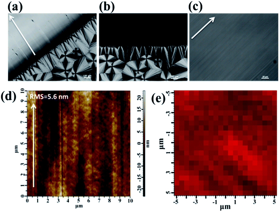 | ||
| Fig. 1 Optical micrographs of the PVDF partial sheared film observed from different angles: (a) the sample was placed in the direction at 45° with respect to horizontal. (b) The same area as in (a) but with a 45° clockwise rotation about the light beam. (c) The magnification POM picture of the sheared region in (a). The scale bars in (a), (b) and (c) are 100 μm, 100 μm, and 20 μm, respectively. (d) Tapping-mode AFM height image of the sheared region. (e) Raman mapping of the Iβ ratio of the sheared film. | ||
Moreover, the blade shear induces not only orientation of crystals but also smooth surface. As shown in the magnification of the sheared region (Fig. 1c), the morphology presents a relatively smooth surface. To better verify the smoothness of the surface, the root-mean-square roughness (RMS) of around 5.6 nm was achieved by tapping-mode atomic force microscopy (AFM) (Fig. 1d). The uniformity, including morphology and component, is important in a practical scenario. The morphological uniformity of sheared film was proved by POM and AFM (Fig. 1c and d). In order to verify the uniformity of component, Raman mapping of the Iβ, the intensity of characteristic Raman shift of β-phase, over the sheared region was performed. As shown in Fig. 1e, it was clear that the color of the mapping is relatively uniform, indicating the uniform β-phase contribution in the films (detailed Raman characterization will be discussed in the later part). These results verified that the blade shear produced high quality films with smooth surface and uniform component distribution.
To further demonstration of the orientation of sheared film, the microstructure of a PVDF film sheared at 158 °C and an unsheared film isothermal crystallization at the same temperature were investigated by AFM. It was found that the edge-on lamellae were well perpendicular to the shear direction (indicated by the arrow) in the sheared film, as shown in Fig. 2a. On the contrary, the film isothermal crystallization without shear process predominantly exhibits the typical banding spherulitic morphology with the mixture of flat-on and edge-on structures, as illustrated in Fig. 2b, which is the part of a spherulite. In addition, crystal size in sheared region was much smaller than spherulite, which indicates that the shear gives rise to very strong nucleation, resulting in the formation of abundant micro-crystallites. The shear caused the formation of well oriented microstructure. In other words, the lamellae were randomly distributed along the direction of crystal growth in the unsheared sample, while the shear induced the molecular chains preferable orientation along the shear direction and formed oriented crystallines.
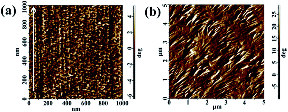 | ||
| Fig. 2 AFM images of (a) A PVDF film sheared at 158 °C, the shear direction indicated by an arrow. (b) A PVDF film without shearing and subsequently isothermal crystallization at 158 °C. | ||
In order to demonstrate the predominant crystalline phase of sheared samples at different temperatures, X-ray diffraction, FTIR and Raman spectroscopy were performed. Fig. 3a showed the XRD patterns of the PVDF films were sheared and subsequently crystallized at four different temperatures, 152 °C, 156 °C, 158 °C and 160 °C. The unsheared film isothermal crystallization at 158 °C was chosen as a representative. It was clearly shown that only the 17.6, 18.3, 19.9, and 26.5° diffraction peaks attributed to α-phase can be distinguished for unsheared sample, which suggests that only the α-phase can be produced by melt-crystallization without shearing at the temperature below 160 °C. However, when the shear was imposed on the PVDF films, except for the aforementioned diffractions, the sheared films showed a new peak at 20.56°, which is assigned to the β-phase and is attributed to the overlapping of (110) and (200) diffractions. Moreover, the relative intensity of peak at 20.56° gradually increased with the shear temperature.36 To quantitatively evaluate the crystalline and β-phase content at different conducting conditions, the degree of crystallinity (Xc) and the phase content of β (Xβ) were calculated using the following equations:37,38
where Aα, Aβ, and Aamorphous indicate the area of the peaks corresponding to the crystalline α, β-phase, and the amorphous fraction, respectively. Xβ is the content of β-phase. As shown in Fig. 3b, the degree of crystallinity and the content of β-phase gradually increase with the sheared temperature. The crystallinity calculated from the samples sheared at 152, 156, 158 and 160 °C is 44.7%, 44.6%, 46.3% and 50.7%, respectively. And the β-phase content of the samples sheared at 152, 156, 158 and 160 °C is 61%, 61.8%, 67.1% and 68.3%, respectively. The results demonstrated that the content of β-phase depends on the shear temperature. In other words, the shear at proper higher temperature is helpful to the generation of β-phase, while effectively suppressing the α-phase.
 | ||
| Fig. 3 (a) The XRD patterns, (b) variation of the degree of crystallinity (Xc) and the phase content of β (Xβ) as a function of sheared temperature (c) infrared spectra and (d) Raman spectra of the sheared and unsheared PVDF films. (e) Variation of the β-phase content F(β) (red) and the intensity ratio Iβ/Iα (blue) as a function of sheared temperature. | ||
The use of FTIR and Raman spectroscopy for material characterization is important because it provides fast, simple, qualitative and quantitative analysis. The FTIR spectra of sheared and unsheared films were presented in Fig. 3c. For the unsheared sample, the characteristic peaks at 610, 765, 796, 855, and 976 cm−1 ascribed to α-phase were clearly detected,39 which is in agreement with previous results. However, it is not surprising that relatively strong absorption peaks at 510, 840, and 1279 cm−1 assigned to β-phase were observed in the sheared films. The result also indicates that the blade shear is helpful to induce the formation of β-phase. Fig. 3d shows Raman spectra of the sheared and unsheared samples. It is evident that only α-phase exists in the unsheared film, because only the characteristic peaks at 284, 535, 610, and 795 cm−1 attributed to the α-phase can be found.40 However, the characteristic peaks of the β-phase appear at 263, 510, and 839 cm−1 were clearly seen in the sheared films at 152 °C, 156 °C, 158 °C and 160 °C, which indicates that the blade shear induces the formation of β-phase even at a temperature lower than 160 °C. The Raman observations agree well with the results of XRD and FTIR.
As shown in XRD, FTIR and Raman measurements, the relative intensity of the β-phase characteristic peaks gradually increased with the temperature, while the intensity of the α-phase gradually decreased. In order to quantify the β-phase content presented in each sample, quantitative FTIR analysis was utilized. Assuming that FTIR absorption follows the Lambert–Beer law, the fraction of the β-phase was calculated using following equation:6,39
The results obtained from the different samples were presented in Fig. 3e. It can be found that the β-phase content, representing by F(β) and the intensity ratio Iβ/Iα, increases remarkably with the shearing temperature at blow 156 °C, and gradually reaches a plateau after that. The relatively high content of β-phase up to 93% was obtained. It was well documented that the shear force induces orientation of polymer chains. In the present case, higher temperature prefers to induce all-trans conformation (β-phase) with the existing of a shear field.
The piezoelectric properties of the sheared samples were also examined by piezoelectric force microscopy (PFM) with an additional voltage amplifier, as shown in Fig. 4. For this measurement, the PVDF films sheared on cleaned ITO coated glass substrate were loaded on a conducting sample holder that is directly connected to the ground of the high voltage amplifier. A conducting AFM cantilever with a Pt coated tip was brought in contact with the films. The response of PVDF films was measured by the reflection of a laser beam from the cantilever as like the regular atomic force microscope (AFM). Fig. 4a shows the evident piezoresponse phase–voltage hysteresis loops for the samples of sheared and unsheared isothermal crystallization at 158 °C. No obvious hysteresis loop was observed for unsheared sample indicating its nonpolar property. The evident hysteresis loop represents the existence of a switchable polarization of the sheared film. When the DC voltage was reversed from −10 V to +10 V, the change in the phase signal was 180°. The DC voltage of abrupt phase change for the sheared film was about 3 V. It can be estimated the apparent coercive field of 500 nm-thick sheared film was about 6 MV m−1. The value is comparable to that of the optimized ordered P(VDF-TrFE) film (∼10 MV m−1)43 and much smaller than that of the corresponding bulk PVDF and P(VDF-TrFE) (50–100 MV m−1).44,45 It is reasonable to speculate that the small apparent coercive field of the sheared sample is attributed to the high polar β-phase crystallinity and the orientation of β-phase crystalline.46,47 The amplitude signal is directly related to the strain of the microscopic region under the tip. Fig. 4b shows the amplitude–voltage butterfly loop. The sudden change of the strain happens at DC voltages of −1.7 V and +0.47 V, respectively. In other words, this electric field is sufficient to polarization switching. The shift of the center of the hysteresis loops from 0 V indicates the possible existence of a built-in field inside the sheared films.48 With decrease of voltage, the amplitude decreases due to contraction of the sheared film. Thus, the amplitude–voltage curve is linear at low and moderate voltage, which also indicates converse piezoelectric effect in the sheared films. The piezoelectric results suggest that the energy cost for electrically polarization switching decreased, and the lower polarization switching voltage was well suited for integrated driving electronics.
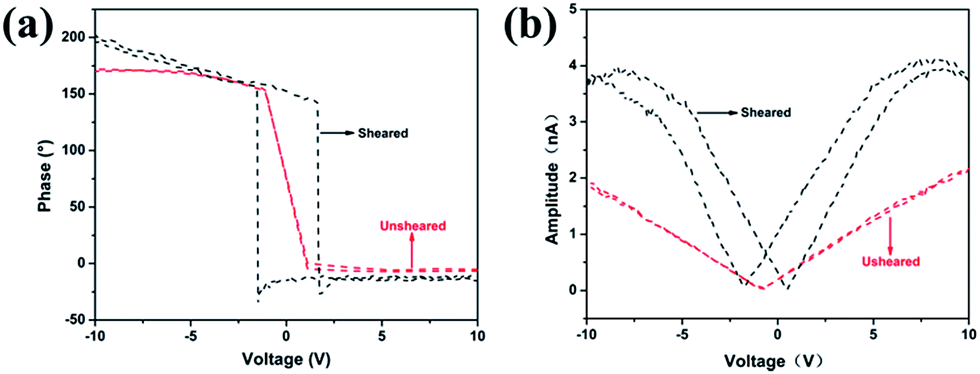 | ||
| Fig. 4 PFM phase–voltage hysteresis loops (a) and amplitude–voltage butterfly loop (b) of sheared and unsheared PVDF films. | ||
A short pulse train was required to obtain ferroelectricity. Here, a forming time of one second at a frequency of 100 Hz was sufficient to obtain a well saturated hysteresis loop for the sheared film. Gold was used as the upper and lower electrodes. The upper electrode was approximately 300 μm2. Fig. 5a shows the ferroelectric hysteresis loops of the sheared films. The unsheared PVDF film did not show P–E hysteresis loop when the electric field was applied due to the α-phase exhibit no polarization and the chains were packed with the dipoles in the opposite direction in the unit cell. On the contrary, well saturated hysteresis loops were observed for the sheared films crystallized at different temperatures. The remnant polarization (Pr) was 4.05, 4.34, 5.02, 6.44 μC cm−2, respectively, with the increase of sheared temperature from 152 °C to 160 °C (Fig. 5b). The gradual increase of Pr is caused by the crystallinity enhancement of polar β-phase with increasing of sheared temperature.49,50 For all sheared samples, the coercive field (Ec) was around 5 to 6.5 MV m−1, which is consistent with the PFM result and is much lower than the value of the bulk samples.44 This effect was associated with the formation of the high content of polar β-phase as well as the preferential orientation of the crystalline due to the shearing of the blade. The shape of the hysteresis loops was not significantly altered, demonstrating similar switching behaviours for all the samples sheared at different temperatures.
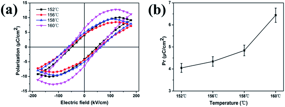 | ||
| Fig. 5 (a) P–E hysteresis loops of the PVDF films sheared at different temperatures, measured at an applied field 180 kV cm−1 at 100 Hz. (b) Dependence of the remnant polarization (Pr) on the different temperature for the sheared PVDF films. | ||
4. Conclusions
We reported a convenient and effective approach for the production of dominantly β-PVDF film. This ferroelectric film was made from the blade shear under different processing temperatures. The morphological results showed that the chain orientation is along the shear direction and crystalline lamellae are oriented perpendicular to the shear direction. Through varying the shear temperature, a different content of the desired polar β-phase was obtained. XRD, FTIR and Raman results revealed that the β-phase was the dominant phase in the sheared film and the content increased with the shear temperature, which suggested that an appropriate high temperature was helpful to the movement of the molecular chain and thus to the formation of all-trans β-phase with the aid of shearing. Maximum relative β phase content was achieved when the shearing temperature was 160 °C. The resulted films exhibited outstanding piezo- and ferroelectronic properties with the coercive field (Ec) was ∼6 MV m−1 and the polarization witching voltage was as low as 3 V. The obtained results suggested that the proposed method show promise application for ferroelectric polymers in future organic electronic industry.Acknowledgements
We greatly acknowledge A Project Funded by the Priority Academic Program Development of Jiangsu Higher Education Institution; the Key Laboratory Funded by Jiangsu advanced welding technology; National Natural Science Foundation of China (No. 51402132), and Six Talent Peaks Project in Jiangsu Province (No. 2015-XCL-028).Notes and references
- H. Kawai, Jpn. J. Appl. Phys., 1969, 8, 975 CrossRef CAS.
- A. J. Lovinger, Science, 1983, 220, 1115–1121 CAS.
- A. J. Lovinger, Polymer, 1981, 22, 412–413 CrossRef CAS.
- A. J. Lovinger, Macromolecules, 1982, 15, 40–44 CrossRef CAS.
- A. Salimi and A. A. Yousefi, Polym. Test., 2003, 22, 699–704 CrossRef CAS.
- V. Sencadas, V. M. Moreira, S. Lanceros-Méndez, A. S. Pouzada and R. Gregorio Jr, Mater. Sci. Forum, 2006, 514–516, 872–876 CrossRef CAS.
- R. Gregorio and E. M. Ueno, J. Mater. Sci., 1999, 34, 4489–4500 CrossRef CAS.
- C. Ribeiro, V. Sencadas, J. L. G. Ribelles and S. Lanceros-Méndez, Soft Mater., 2010, 8, 274–287 CrossRef CAS.
- D. Yang and C. Ye, J. Mater. Sci. Lett., 1987, 6, 599–603 CrossRef CAS.
- A. Gradys, P. Sajkiewicz, S. Adamovsky, A. Minakov and C. Schick, Thermochim. Acta, 2007, 461, 153–157 CrossRef CAS.
- H. J. Ye, W. Z. Shao and L. Zhen, J. Appl. Polym. Sci., 2013, 129, 2940–2949 CrossRef CAS.
- S. Yu, W. Zheng, W. Yu, Y. Zhang, Q. Jiang and Z. Zhao, Macromolecules, 2009, 42, 8870–8874 CrossRef CAS.
- T. Kuilla, S. Bhadra, D. Yao, N. H. Kim, S. Bose and J. H. Lee, Prog. Polym. Sci., 2010, 35, 1350–1375 CrossRef CAS.
- S. J. Kang, I. Bae, J. H. Choi, Y. J. Park, P. S. Jo, Y. Kim, K. J. Kim, J. M. Myoung, E. Kim and C. Park, J. Mater. Chem., 2011, 21, 3619–3624 RSC.
- R. Gregorio and R. C. Capitão, J. Mater. Sci., 2000, 35, 299–306 CrossRef CAS.
- R. Gregorio, J. Appl. Polym. Sci., 2006, 100, 3272–3279 CrossRef CAS.
- L. Persano, C. Dagdeviren, Y. Su, Y. Zhang, S. Girardo, D. Pisignano, Y. Huang and J. A. Rogers, Nat. Commun., 2013, 4, 67–88 Search PubMed.
- Y. Berdichevsky and Y. H. Lo, Adv. Mater., 2006, 18, 122–125 CrossRef CAS.
- Y. Qi, N. T. Jafferis, L. Kenneth Jr, C. M. Lee, H. Ahmad and M. C. Mcalpine, Nano Lett., 2010, 10, 524–528 CrossRef CAS PubMed.
- J. X. Zhang, B. Xiang, Q. He, J. Seidel, R. J. Zeches, P. Yu, S. Y. Yang, C. H. Wang, Y. H. Chu and L. W. Martin, Nat. Nanotechnol., 2011, 6, 98–102 CrossRef CAS PubMed.
- T. Someya, T. Sekitani, S. Iba, Y. Kato, H. Kawaguchi and T. Sakurai, Proc. Natl. Acad. Sci. U. S. A., 2004, 101, 9966–9970 CrossRef CAS PubMed.
- M. C. Branciforti, V. Sencadas, S. Lanceros-Mendez and R. Gregorio Jr, J. Polym. Sci., Part B: Polym. Phys., 2007, 45, 2793–2801 CrossRef CAS.
- J. Gomes, J. Serrado Nunes, V. Sencadas and S. Lancerosmendez, Smart Mater. Struct., 2010, 19, 065010 CrossRef.
- V. F. Cardoso, G. Minas, C. M. Costa, C. J. Tavares and S. Lancerosmendez, Smart Mater. Struct., 2011, 20, 087002 CrossRef.
- S. Ramasundaram, Y. Sun, K. J. Kim and J. S. Lee, Macromol. Chem. Phys., 2008, 209, 2516–2526 CrossRef CAS.
- W. Eisenmenger, H. Schmidt and B. Dehlen, Braz. J. Phys., 1999, 29, 295–305 CrossRef CAS.
- C. Chang, V. H. Tran, J. Wang, Y. K. Fuh and L. Lin, Nano Lett., 2010, 10, 726–731 CrossRef CAS PubMed.
- S. Manna and A. K. Nandi, J. Phys. Chem. C, 2007, 111, 14670–14680 CAS.
- V. Cauda, S. Stassi, K. Bejtka and G. Canavese, ACS Appl. Mater. Interfaces, 2013, 5, 6430–6437 CAS.
- X. Li, Y. F. Lim, K. Yao, F. E. H. Tay and K. H. Seah, Chem. Mater., 2013, 25, 524–529 CrossRef CAS.
- H. Zhu, M. Mitsuishi and T. Miyashita, Macromolecules, 2012, 45, 9076–9084 CrossRef CAS.
- J. L. Wang, B. L. Liu, X. L. Zhao, B. B. Tian, Y. H. Zou, S. Sun, H. Shen, J. L. Sun, X. J. Meng and J. H. Chu, Appl. Phys. Lett., 2014, 104, 1232 Search PubMed.
- S. Maji, P. K. Sarkar, L. Aggarwal, S. K. Ghosh, D. Mandal, G. Sheet and S. Acharya, Phys. Chem. Chem. Phys., 2015, 17, 8159–8165 RSC.
- J. Varga and J. Karger-Kocsis, J. Mater. Sci. Lett., 1993, 13, 1069–1071 Search PubMed.
- J. Loos, T. Schimanski, J. Hofman, T. Peijs and P. J. Lemstra, Polymer, 2001, 42, 3827–3834 CrossRef CAS.
- B. Mohammadi, A. A. Yousefi and S. M. Bellah, Polym. Test., 2007, 26, 42–50 CrossRef CAS.
- V. Tiwari and G. Srivastava, J. Polym. Res., 2014, 21, 1–8 CAS.
- R. Gregorio Jr and M. Cestari, J. Polym. Sci., Part B: Polym. Phys., 1994, 32, 859–870 Search PubMed.
- P. Martins, A. C. Lopes and S. Lanceros-Mendez, Prog. Polym. Sci., 2014, 39, 683–706 CrossRef CAS.
- C. J. L. Constantino, A. E. Job, R. D. Simoes and J. A. Giacometti, International Symposium on Electrets, 2005, vol. 6, pp. 178–181 Search PubMed.
- M. T. Riosbaas, K. J. Loh, G. O'Bryan and B. R. Loyola, Sensors & Smart Structures Technologies for Civil Mechanical & Aerospace Systems, 2014, vol. 9061, pp. 90610Z–90611Z Search PubMed.
- C. J. Constantino, A. E. Job, R. D. Simões, J. A. Giacometti, V. Zucolotto, O. N. Oliveira, G. Gozzi and D. L. Chinaglia, Appl. Spectrosc., 2005, 59, 275–279 CrossRef CAS PubMed.
- Z. Hu, M. Tian, B. Nysten and A. M. Jonas, Nat. Mater., 2008, 8, 62–67 CrossRef PubMed.
- S. H. Lee, Y. Xu and Y. Y. Noh, Chem. Mater., 2010, 23, 341–358 Search PubMed.
- R. C. G. Naber, P. W. M. Blom, A. W. Marsman and D. M. De Leeuw, Appl. Phys. Lett., 2004, 85, 2032–2034 CrossRef CAS.
- E. Bellet-Amalric and J. F. Legrand, Eur. Phys. J. B, 1998, 3, 225–236 CrossRef CAS.
- B. H. S. Nalwa, Ferroelectric polymers: chemistry, physics, and applications, M. Dekker, Inc, 1995 Search PubMed.
- Q. Li, Y. Liu, J. Schiemer, P. Smith, Z. Li, R. L. Withers and Z. Xu, Appl. Phys. Lett., 2011, 98, 092908 CrossRef.
- I. Y. Dmitriev, V. K. Lavrentyev and G. K. Elyashevich, Polym. Sci., 2006, 48, 272–277 Search PubMed.
- H. J. Jung, J. Chang, Y. J. Park, S. J. Kang, B. Lotz, J. Huh and C. Park, Macromolecules, 2009, 42, 4148–4154 CrossRef CAS.
| This journal is © The Royal Society of Chemistry 2017 |