 Open Access Article
Creative Commons Attribution 3.0 Unported Licence
Effect of fluorination on n-type conjugated polymers for all-polymer solar cells
Xiangzhi Liab,
Xiaoyuan Liuab,
Po Sunab,
Yaomiao Fenga,
Haiquan Shana,
Xia Wub,
Jiaju Xua,
Chun Huang*b,
Zhi-Kuan Chen*b and
Zong-Xiang Xu *a
*a
aDepartment of Chemistry, South University of Science and Technology of China, Shenzhen, P. R. China. E-mail: xu.zx@sustc.edu.cn
bKey Laboratory of Flexible Electronics (KLOFE), Institute of Advanced Materials (IAM), National Jiangsu Synergistic Innovation Center for Advanced Materials, Nanjing Tech University, 30 South Puzhu Road, Nanjing 211816, China. E-mail: iamzkchen@njtech.edu.cn; iamchunhuang@njtech.edu.cn
First published on 17th March 2017
Abstract
Four naphthalene diimide (NDI) based donor–acceptor conjugated polymers for using in all-polymer organic solar cells were synthesized and characterized. The effect of inclusion of a different number of fluorine atoms on the donor portion of the polymer was thoroughly investigated via a range of techniques. Fluorination of the polymer backbone lowered both the highest occupied molecular orbital (HOMO) and the lowest unoccupied molecular orbital (LUMO) and simultaneously broadened the energy bandgap of the polymer. Incorporation of a different number of fluorine atoms on the donor portion of the polymer significantly affected the solar cells' power conversion efficiency from 0.67% to 2.50%. The “fluorine” effect suggests fluorine substitution should be considered for achieving high performance PSCs in the future design of new materials.
Introduction
During the past decade, polymer solar cells (PSCs) have attracted considerable academic and industrial attention owing to their potential applications in low-cost solar energy production.1–3 The best performing PSCs to date consist of a p-type semiconducting polymer as the electron donor and a fullerene derivative as the electron acceptor.4 Despite the essential role of fullerenes in a PSC, there are still several drawbacks to using fullerene-based acceptors (e.g., PC61BM/PC71BM), such as poor light absorption, relatively low-lying lowest unoccupied molecular orbital (LUMO) level, and high production cost, which may impede their widespread deployment in practical applications. To surmount these problems, vigorous efforts have been dedicated to the development of non fullerene electron acceptors. All-polymer solar cells (all-PSCs) have attracted significant interest recently because they have potential advantages over polymer/fullerene systems, including enhanced absorption coefficients, increased photovoltage, superior photochemical, thermal, and mechanical robustness, and facile control of solution viscosity and the industrial coating process.5–9 Although all-polymer solar cells have shown power conversion efficiencies (PCEs) up to 3–8%,10–13 they are still at the infant stage relative to polymer/fullerene systems, which exhibit PCEs of 8–10%.14–17 Naphthalene diimides (NDIs) are an important electron-accepting building block previously used to design acceptor (n-type) polymers for all-polymer solar cells. These polymers have shown promising properties that warrant their consideration as an efficient electron acceptor for all-polymer solar cells owing to their low-lying LUMO levels and high electron mobilities.18,19 Nevertheless, the performance of all-PSCs using such NDI-based n-type polymers is still far below that of the typical fullerene-based solar cells, with the best device PCEs approaching to 7%.10 The low PCEs of all-PSCs are attributed to the many undesirable features of bulk heterojunction (BHJ) films, e.g., mismatched energy levels between the donors and acceptors, large phase-separated domain size, inhomogeneous compositions in each phase, and a low degree of ordering of the polymer chains, which hamper the generation and transportation of free charge carriers in the films and thus the device performance.20,21 It is indeed a great challenge to achieve an optimal BHJ morphology with a few tens of nanosized domains in all-PSCs, because of the significantly reduced entropic contribution from two polymer species that decreases their mixing.17,22Recently, it has been shown that the incorporation of electron-withdrawing halogen groups such as F onto the polymer backbone can afford the derived polymers with reasonable n-type properties.23,24 Fluorine atoms have unique properties, such as the highest Pauling electronegativity of 4.0 and a small atomic size (van der Waals radius, r = 1.35 Å, only slightly larger than hydrogen, r = 1.2 Å); thus, fluorine substitution may not cause steric hindrance to the molecular packing of fluorine-substituted polymers.25–27 In addition, interactions between C–F, S–F, and H–C in fluorinated organic compounds may promote molecular organization and crystallization,28 enabling the tuning of bulk-heterojunction (BHJ) morphology, polymer domain size, and the ordering of the polymer chains, which may enhance the efficiency of exciton dissociation and charge transport.17,45 Hence, the degree of fluorination of the conjugated polymer (i.e., the number of substituted fluorine atoms in one repeating unit of the polymer) should be optimized to enhance the properties of an n-type conjugated polymer by rational fluorination.29,30 Although it has been reported that the fluorination of conjugated polymers can complicate the morphology of the bulk heterojunction active layer,31–34,46 there are few examples of fluorinated polymer acceptors reported to date,11,35 and knowledge of how to further improve solar cell efficiency through polymer development is still limited. Therefore, it is necessary to carry out detailed research to elucidate the structure/property relationship of such polymers.
Here, we report the synthesis of alternating copolymers composed of NDI and a fluorinated phenyl unit, where the total number of fluorine atoms in the polymer was controlled by the number of fluorine substitutions on the phenylene unit. The effect of the number of fluorine substitutions on the photophysical properties of the polymers and their performance as acceptors for all-PSC devices was investigated. It was observed that increasing fluorine substitution on the phenylene unit lowered the frontier energy levels and enhanced the molecular ordering of the conjugated polymers. Compared with the non-fluorinated polymer (denoted as PNDI-0F-Ph), the monofluorinated polymer (PNDI-1F-Ph) and the difluorinated polymer (PNDI-2F-Ph) showed higher PSC performance. However, the tetra-fluorinated polymer (PNDI-4F-Ph) showed lower PSC performance. Fig. 1 depicted the chemical structures of electron donor polymer poly[4,8-bis(5-(2-ethylhexyl)thiophen-2-yl)benzo[1,2-b:4,5b′]dithiophene-co-3-fluorothieno[3,4-b]thiophene-2-carboxylate] (PTB7-Th) and cathode interlayer (PDIN). The energy level diagram of all solar cell materials used in this work is also listed in Fig. 1. Preliminary tests of BHJ solar cells using PNDI-2F-Ph as the electron acceptor and PTB7-Th as the electron donor in a ratio of 1![[thin space (1/6-em)]](https://www.rsc.org/images/entities/char_2009.gif) :
:![[thin space (1/6-em)]](https://www.rsc.org/images/entities/char_2009.gif) 1.5 yielded an open circuit voltage (VOC) of 0.720 V, a short circuit current density (JSC) of 9.60 mA cm−2, a fill factor (FF) of 0.366, and a PCE of 2.50%. It should be noted that these devices were fabricated using a simple spin-coating process without the use of a formulation additive such as 1,8-diiodooctane (DIO) or post treatments such as solvent or thermal annealing. These results indicated that fluorination of the polymer backbone exerted an important effect not only on electronic properties but also on the morphological compatibility of the polymer with the donor.
1.5 yielded an open circuit voltage (VOC) of 0.720 V, a short circuit current density (JSC) of 9.60 mA cm−2, a fill factor (FF) of 0.366, and a PCE of 2.50%. It should be noted that these devices were fabricated using a simple spin-coating process without the use of a formulation additive such as 1,8-diiodooctane (DIO) or post treatments such as solvent or thermal annealing. These results indicated that fluorination of the polymer backbone exerted an important effect not only on electronic properties but also on the morphological compatibility of the polymer with the donor.
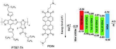 | ||
| Fig. 1 Chemical structures of PTB7-Th and PDIN used in the solar cell stacks, and the schematic energy level diagram of the all-polymer solar cells. | ||
Experimental section
Materials
The polymers PTB7-Th were purchased from Lumitech Inc. and used as received. Solvent of toluene was dried over Na/benzophenone ketyl and freshly distilled before use. The other reagents and solvents used in this work were commercially purchased and used without further purification. All air- and water-sensitive reactions were performed under Ar atmosphere. The detailed synthetic processes of the other compounds are as follows.Synthetic procedures
The synthesis of the four monomers 1a–1b has been reported elsewhere.36Measurements and characterization
1H NMR data were acquired on a Bruker DPX 400 MHz spectrometer. Differential scanning calorimetry (DSC) was carried out under nitrogen on a TA Instrument DSC Q100 instrument (scanning rate of 10 °C min−1). Thermogravimetric analysis (TGA) was carried out using a TGA Q500 instrument (heating rate of 10 °C min−1). Molecular weight determinations were carried out in hot 1,2-dichlorobenzene (120 °C) on a Shimadzu Prominence CBM-20A series HPLC using Agilent PLGel 5 micrometer Mixed-C column (79911 GP-MXC) with polystyrene calibration standards. Electrochemical measurements were carried out in a three-electrode glass cell at room temperature. A solution of 0.1 M tetrabutyl ammonium tetrafluoroborate in acetonitrile (MeCN) was used as the supporting electrolyte with ferrocenium/ferrocene couple (Fc/Fc+) as the internal standard in all measurements. Commercially available glassy carbon disk (CH Instruments, Inc.) served as the working electrode, Ag/AgCl electrode as the reference electrode, and Pt wire as the counter electrode. The glassy carbon disk was polished with a 1 μm α-alumina slurry (Linde) and then with a 0.3 μm α-alumina slurry (Linde) on a microcloth (Buehler Co.). All the solutions were degassed with nitrogen for 10 min prior to measurement. UV-vis-NIR spectra were recorded on a Shimadzu model 2501-PC. The nanoscale morphology of the blended films was carried out using atomic force microscope (AFM) in the tapping mode (Veeco Multipode V, tapping mode). Deionized water droplets (about 2 μL) were dropped carefully onto the surface.Fabrication and characterization of the photovoltaic cells
The PSCs with the following structures were fabricated: ITO/PEDOT:PSS/PTB7-Th:acceptor/PDIN/Al. The patterned ITO glass was precleaned in an ultrasonic bath of acetone and isopropyl alcohol, and treated in an ultraviolet-ozone chamber (Jelight Company, Irvine, CA) for 20 min. A thin layer (30 nm) of PEDOT:PSS (Baytron P, now Clevios VP AI 4083, from H. C. Starck, Leverkusen, Germany) was spin-coated (5000 rpm for 60 s) onto the ITO glass and baked at 150 °C for 15 min. A solution (total of 20 mg mL−1) of PTB7-Th:polymer acceptor blend was subsequently spin-coated (2000 rpm for 60 s) on the PEDOT:PSS layer to form a photosensitive layer (ca.100 nm thick). The thickness of the photosensitive layer was measured using an Ambios Technology (Santa Cruz, CA) XP-2 profilometer. The methanol solution (0.2% acetic acid) of PDIN at a concentration of 1.5 mg mL−1 was deposited on the active layer at 3000 rpm for 30 s, giving a PDIN layer ca. 13 nm thick. An aluminum (ca. 100 nm) layer was subsequently evaporated onto the surface of the PDIN layer under vacuum (ca. 10−6 Pa) to form the negative electrode. The active area of the device was 0.1 cm2. The J–V curve was measured with a computer controlled Keithley (Zolix ss150 Solar Simulator) 236 Source Measure Unit. A xenon lamp coupled with AM1.5 solar spectrum filters was used as the light source, and the optical power at the sample was 100 mW cm−2. The light intensity of the solar simulator was calibrated using a standard silicon solar cell. The IPCE spectrum was measured using a Solar Cell QE/IPCE Measurement System (Zolix Solar cell scan 100) model SR830 DSP lock-in amplifier coupled with a WDG3 monochromator and 500 W xenon lamp.Result and discussion
The synthetic routes of the monomers and corresponding polymers used in this work are outlined in Scheme 1. The syntheses of all monomers are described in the Experimental section. Four polymers (PNDI-0F-Ph, PNDI-1F-Ph, PNDI-2F-Ph, PNDI-4F-Ph) with different numbers of fluorine substitution were synthesized by a Stille coupling reaction between the dibromide monomer 4,9-dibromo-2,7-bis(2-decyltetradecyl)-benzo[lmn]-[3,8]-phenanth-roline-1,3,6,8(2H,7H)-tetraone and the desired monomers (2a, 2b, 2c, and 2d) using Pd(PPh3)4 as the catalyst. The obtained polymers were precipitated in methanol and then purified by Soxhlet extraction to remove oligomers and other impurities. Branched long alkyl chains (2-decyltetradecyl) were introduced to the conjugated backbone to ensure the solubility of the fluorinated polymers in organic solvents. The obtained polymers were found to exhibit good solubility in many chlorinated solvents (i.e., chloroform and chlorobenzene) except for polymer PNDI-4F-Ph. The structures of the polymers were determined with 1H NMR spectroscopy, and were confirmed to be consistent with the proposed structures. The molecular weight and polydispersity index (Mw/Mn) of the polymers were measured by gel permeation chromatography (GPC) against polystyrene standards in o-dichlorobenzene at 120 °C. The results are shown in Table 1. PNDI-0F-Ph, PNDI-1F-Ph, PNDI-2F-Ph, and PNDI-4F-Ph were found to have moderate number-averaged molecular weights of 39.5 kD, 54.8 kD, 51.3 kD, and 39.2 kD and a polydispersity (Mw/Mn) of 2.1, 1.8, 1.8, and 1.9, respectively.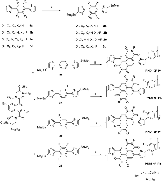 | ||
| Scheme 1 Synthetic procedures for PNDI-0F-Ph, PNDI-1F-Ph, PNDI-2F-Ph, PNDI-4F-Ph polymers. (i) n-Butyl lithium, trimethyltin chloride, THF, −75 °C, overnight, (ii) Pd(PPh3)4, toluene, 110 °C, 24 h. | ||
| Polymer | αa (×106 m−1) | Mn (kDa) | Mw (kDa) | Mw/Mn | Eredonset (eV) | HOMO (eV) | LUMO (eV) | Eoptg (eV) |
|---|---|---|---|---|---|---|---|---|
a Max UV-vis absorption-coefficient (α) of PTB7-Th:polymer acceptor (1![[thin space (1/6-em)]](https://www.rsc.org/images/entities/char_2009.gif) : :![[thin space (1/6-em)]](https://www.rsc.org/images/entities/char_2009.gif) 1.5 w/w) blend films. 1.5 w/w) blend films. |
||||||||
| PNDI-0F-Ph | 0.168 | 39.5 | 82.4 | 2.1 | −0.52 | −5.48 | −3.88 | 1.60 |
| PNDI-1F-Ph | 0.247 | 54.8 | 98.6 | 1.8 | −0.51 | −5.49 | −3.89 | 1.60 |
| PNDI-2F-Ph | 0.177 | 51.3 | 91.2 | 1.8 | −0.49 | −5.59 | −3.91 | 1.68 |
| PNDI-4F-Ph | 0.145 | 39.2 | 73.1 | 1.9 | −0.45 | −5.69 | −3.95 | 1.74 |
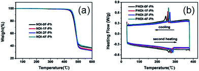
As shown in Fig. 2a, thermogravimetric analysis (TGA) under nitrogen indicated that all four polymers exhibited similarly good thermal stability, with decomposition temperatures (Td, defined as the temperature at which 5% of the mass had been lost) that exceeded ca. 440 °C. The glass transition temperatures (Tg) of the polymers obtained using differential scanning calorimetry (DSC) analysis under nitrogen are also shown in Fig. 2b. The nonfluorinated PNDI-0F-Ph showed the lowest melting temperature (265 °C), while the fluorination led to increased melting temperatures of 276 °C, 285 °C, and 283 °C for the mono-, di-, and tetrafluorinated copolymers, respectively. This was caused by increased aggregation in the fluorinated polymers. The DSC traces of PNDI-0F-Ph, PNDI-1F-Ph, PNDI-2F-Ph, PNDI-4F-Ph showed exothermic peaks at 245 °C, 258 °C, 270 °C, and 264 °C, respectively, during cooling, attributed to the crystallization of the polymer backbone.
The optical absorption of the four polymers was measured in solution (Fig. 3a) and as a thin film (Fig. 3b) using UV-vis absorption spectroscopy. In o-dichlorobenzene solution, all polymers exhibited a broad absorption in the region of 300–800 nm. The polymers showed two distinct absorption bands at 300–450 nm and 500–800 nm, which could be assigned to π–π* or n–π* transition of the NDI chromophore and intramolecular charge transfer (ICT), respectively.37 These absorption features are typically observed in the visible region for NDI-based conjugated copolymers. Thin films of the four polymers exhibited slightly red-shifted absorption relative to their corresponding solutions owing to the aggregation of the copolymers in the solid state. Introducing more fluorine substitution on the phenylene unit of the polymer blue-shifted both the absorption onset (λonset) and maximum (λmax) of the polymers. For example, the λonset and λmax values of PNDI-4F-Ph were ∼170 nm and 60–70 nm blue-shifted from those of PNDI-0F-Ph, respectively. This led to a widening of the energy bandgap, as shown in Table 1. A similar effect was reported for a fluorine-substituted thiophene oligomer.38 The absorption spectra of PNDI-1F-Ph and PNDI-0F-Ph were very similar, indicating that monofluorinated substitution of the phenylene unit of PNDI-1F-Ph did not change its optical properties significantly. The spectroscopic data of the polymers are summarized in Table 1. The optical bandgap (Eoptg) of the four polymers was determined from the onset of absorption (λonset). The bandgaps of PNDI-0F-Ph and PNDI-1F-Ph were found to be nearly identical (1.60 eV), while PNDI-2F-Ph and PNDI-4F-Ph had slightly wider bandgaps of 1.68 eV and 1.74 eV.
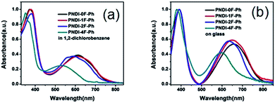 | ||
| Fig. 3 UV-vis absorption spectra of the polymers in a 1,2-dichlorobenzene solution (a) and as a thin film (b). | ||
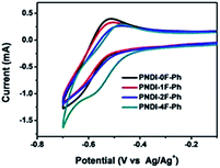
The electrochemical properties of the copolymers were investigated by cyclic voltammetry (CV) using films deposited on a glassy carbon working electrode in an acetonitrile solution containing 0.1 mol L−1 tetrabutyl ammonium tetrafluoroborate and a potential scan rate of 100 mV s−1. Fluorine substitution on the phenylene unit was expected to influence the electrochemical properties of the polymers. Because the strong electron withdrawing ability of atomic fluorine lowers the frontier energy levels of the polymers, the HOMO energy level and LUMO energy level became deeper as the number of fluorine substitutions was increased, in good agreement with previous reports.30,39 The LUMOs of PNDI-0F-Ph, PNDI-1F-Ph, PNDI-2F-Ph, and PNDI-4F-Ph were estimated to be −3.88 eV, −3.89 eV, −3.92 eV and −3.95 eV, respectively, from the onset of their reduction peaks referenced to the Ag/AgCl redox couple. (Table 1 and Fig. 4). These low lying LUMO levels suggest that all four polymers were good electron acceptors. According to the band gaps and LUMOs of the polymers, the HOMOs of PNDI-0F-Ph, PNDI-1F-Ph, PNDI-2F-Ph, and PNDI-4F-Ph were extracted from the UV-vis band gap in solid state, which were calculated to be −5.48 eV, −5.49 eV, −5.59 eV, and −5.69 eV, respectively. These results reveal that introduction of fluorine to the phenylene units of the polymer backbone reduced both the HOMO and LUMO energy levels, although the energy levels of PNDI-0F-Ph and PNDI-1F-Ph were very similar. Fig. 1 depicts the energy diagrams of the acceptors and the selected polymer donor PTB7-Th. The HOMO and LUMO energies of the polymer acceptors well match those of the donor polymer PTB7-Th and the interface materials PDIN and PEDOT:PSS.
The photovoltaic properties of the polymers were studied in solar cells with structures of ITO/PEDOT:PSS/PTB7-Th:polymer acceptor/PDIN/Al. PEDOT:PSS was used as a hole injection layer and PDIN was used as a cathode interlayer. The active layers were spin-coated from 1,2-dichlorobenzene (DCB) solutions of the polymer acceptor and PTB7-Th. The optimized weight ratio between the polymer acceptor and PTB7-Th was 1![[thin space (1/6-em)]](https://www.rsc.org/images/entities/char_2009.gif) :
:![[thin space (1/6-em)]](https://www.rsc.org/images/entities/char_2009.gif) 1.5. Fig. 5a shows the curves of current density versus voltage (I–V), measured under AM1.5 conditions at 100 mW cm−2. The resulting JSC, VOC, FF, and PCE values were determined from the I–V curves, and all of the relevant solar cell parameters are summarized in Table 2. Moreover, the corresponding dependency of the photovoltaic parameters, the VOC, JSC, FF, and PCE data, on the number of fluorine atoms are shown in Fig. 6. The optimized device using a blend of PTB7-Th:PNDI-0F-Ph exhibited a PCE of 1.38% with a VOC of 0.82 V, a JSC of 4.66 mA cm−2, and a FF of 0.36. Under the same conditions, the optimized device using PNDI-1F-Ph as an acceptor exhibited an improved PCE of 2.42% with a JSC of 8.09 mA cm−2, a VOC exhibited an improvement in device PCE compared with that using PNDI-0F-Ph. The devices exhibited a PCE of 2.50% at a JSC of 9.60 mA cm−2, a VOC of 0.72 V and a FF of 0.38, yielding an 81% higher PCE than that of the device with PNDI-0F-Ph. However, the polymer PNDI-4F-Ph, which had tetrafluorinated phenylene units, exhibited a lower device performance, with a PCE below 1%. This demonstrates that the degree of fluorination of the conjugated polymer backbone should be controlled to achieve high efficiency.
1.5. Fig. 5a shows the curves of current density versus voltage (I–V), measured under AM1.5 conditions at 100 mW cm−2. The resulting JSC, VOC, FF, and PCE values were determined from the I–V curves, and all of the relevant solar cell parameters are summarized in Table 2. Moreover, the corresponding dependency of the photovoltaic parameters, the VOC, JSC, FF, and PCE data, on the number of fluorine atoms are shown in Fig. 6. The optimized device using a blend of PTB7-Th:PNDI-0F-Ph exhibited a PCE of 1.38% with a VOC of 0.82 V, a JSC of 4.66 mA cm−2, and a FF of 0.36. Under the same conditions, the optimized device using PNDI-1F-Ph as an acceptor exhibited an improved PCE of 2.42% with a JSC of 8.09 mA cm−2, a VOC exhibited an improvement in device PCE compared with that using PNDI-0F-Ph. The devices exhibited a PCE of 2.50% at a JSC of 9.60 mA cm−2, a VOC of 0.72 V and a FF of 0.38, yielding an 81% higher PCE than that of the device with PNDI-0F-Ph. However, the polymer PNDI-4F-Ph, which had tetrafluorinated phenylene units, exhibited a lower device performance, with a PCE below 1%. This demonstrates that the degree of fluorination of the conjugated polymer backbone should be controlled to achieve high efficiency.
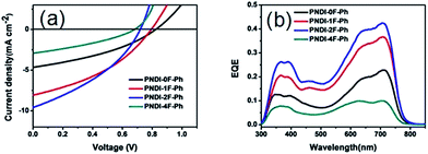 | ||
| Fig. 5 (a) J–V curves and (b) EQE spectra of PTB7-Th:polymer solar cells processed from DCB in a device with the structure ITO/PEDOT:PSS/PTB7-Th:acceptor/PDIN/Al. | ||
![[thin space (1/6-em)]](https://www.rsc.org/images/entities/char_2009.gif) :
:![[thin space (1/6-em)]](https://www.rsc.org/images/entities/char_2009.gif) 1.5 w/w) blend processed from DCB under standard AM 1.5G illumination
1.5 w/w) blend processed from DCB under standard AM 1.5G illumination
| Polymer | VOC [V] | JSC [mA cm−2] | FF (%) | PCEa (%) | μh [cm2 V−1 s−1] | μe [cm2 V−1 s−1] |
|---|---|---|---|---|---|---|
| a The PCE values in parentheses are the average PCE values. | ||||||
| PNDI-0F-Ph | 0.824 | 4.66 | 36.0 | 1.38 (1.31) | 6.20 × 10⁻⁵ | 8.07 × 10⁻⁶ |
| PNDI-1F-Ph | 0.790 | 8.09 | 37.9 | 2.42 (2.35) | 1.41 × 10⁻⁴ | 2.58 × 10⁻⁵ |
| PNDI-2F-Ph | 0.720 | 9.60 | 36.1 | 2.50 (2.44) | 1.19 × 10⁻⁴ | 6.14 × 10⁻⁵ |
| PNDI-4F-Ph | 0.681 | 2.93 | 33.7 | 0.67 (0.62) | 3.98 × 10⁻⁵ | 6.38 × 10⁻⁶ |
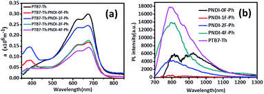 | ||
Fig. 6 UV-vis absorption-coefficient (α) of PTB7-Th:polymer acceptor (1![[thin space (1/6-em)]](https://www.rsc.org/images/entities/char_2009.gif) : :![[thin space (1/6-em)]](https://www.rsc.org/images/entities/char_2009.gif) 1.5 w/w) blend films (a) and photoluminescence of the corresponding blend films (b). 1.5 w/w) blend films (a) and photoluminescence of the corresponding blend films (b). | ||
The origin of the VOC has previously been related to the energy difference between the LUMO of the polymer acceptor and the HOMO of the donor polymer,40,41 as long as there is good ohmic contact between the active layer and device electrodes.42 This value, (ELUMO(acceptor) − EHOMO(donor))/e, represents the maximum achievable voltage from a BHJ device, but is rarely observed owing to losses originating from band offsets, internal space charge, and molecular reorganizational energy characterized by the Stokes shift.43 Both Table 2 and Fig. 6a show that increasing the number of fluorine substituents decreased the observed VOC of the photovoltaic devices. Importantly, the VOC was increased by nearly the same amount as the LUMO level was reduced with the fluorine substitution, indicating this was the sole cause of the decreased VOC. As a result, the VOC of PNDI-0F-Ph was larger than that of PNDI-1F-Ph, PNDI-2F-Ph, and PNDI-4F-Ph, and the VOC of the device was decreased from 0.82 V to 0.68 V. Note here that the LUMO energy levels of PNDI-1F-Ph, PNDI-2F-Ph, and PNDI-4F-Ph were deeper than that of PNDI-0F-Ph.
JSC displayed an interesting trend that depended upon the thickness and the number of fluorine substitutions, as shown in Table 2. Although PNDI-1F-Ph had similar energy levels to those of PNDI-0F-Ph and the same backbone structure except for the fluorine on phenylene unit, the JSC of PNDI-1F-Ph was 73% higher than that of PNDI-0F-Ph. A further improvement in JSC was achieved when the number of fluorine substitutions was increased. PNDI-2F-Ph exhibited the highest JSC (9.60 mA cm−2) among all of the polymers. However, PNDI-4F-Ph showed the lowest JSC among all of the polymers, with a value 7% smaller than that of PNDI-0F-Ph, which may have been caused by poor film-formation owing to its poor solubility. Fig. 6a illustrates the absorption spectra of the studied BHJ systems. The blend films of PTB7-Th:PNDI-1F-Ph and PNDI-2F-Ph exhibit broader absorption bands than those of the blend films of PTB7-Th:PNDI-0F-Ph and PTB7-Th:PNDI-4F-Ph, leading to the increased light harvest of the corresponding devices and resulting in higher JSC. The devices fabricated from the copolymer PNDI-2F-Ph exhibited higher EQEs over the wavelength range from 300 nm to 800 nm than those using PNDI-0F-Ph, PNDI-1F-Ph, and PNDI-4F-Ph, which is consistent with the higher JSC values observed for the PNDI-2F-Ph based devices. The high energy region (300 nm to 500 nm) of the EQE spectra (Fig. 5b) clearly indicate that photoexcitation also occurred within the acceptor and contributed to the observed power conversion.
Space-charge-limited current (SCLC) measurements were used to investigate bulk charge transport in the blend devices to gain a better understanding of their photovoltaic properties. Hole-only devices with the structure ITO/PEDOT:PSS/donor:acceptor blend/Au and electron-only devices with the structure Al/donor:acceptor blend/Al were fabricated and characterized. SCLC fittings to the current–voltage characteristics of the hole-only devices (Fig. 7a) and electron-only devices (Fig. 7b) yielded the carrier mobilities summarized in Table 2. The blend of PTB7-Th:PNDI-0F-Ph exhibited a hole mobility of 6.20 × 10⁻⁵ cm2 V−1 s−1 and an electron mobility of 8.07 × 10⁻⁶ cm2 V−1 s−1 (μh/μe = 7.46), respectively. Compared with the PTB7-Th:PNDI-0F-Ph blend system, the PTB7-Th:PNDI-1F-Ph blend exhibited a higher charge transport (μh = 1.41 × 10⁻⁴ cm2 V−1 s−1, μe = 2.58 × 10⁻⁵ cm2 V−1 s−1 (μh/μe = 5.47)). The PTB7-Th:PNDI-2F-Ph blend showed the best balanced charge transport (μh = 1.19 × 10⁻⁴ cm2 V−1 s−1, μe = 6.14 × 10⁻⁵ cm2 V−1 s−1, μh/μe = 1.94). Thus, this significant improvement in charge transport was key to the improved transport of electrons to the electrode, which resulted in the higher JSC values of the all-PSC devices. Photoluminescence (PL) measurement was used to probe the effect of the n-type polymer for exciton dissociation and charge generation. For the PTB7-Th:PNDI-1F-Ph and PTB7-Th:PNDI-2F-Ph blends, the PL of PNDI-1F-Ph and PNDI-2F-Ph were quenched in a quantum yield of 94% and 76%, respectively, while the PTB7-Th:PNDI-0F-Ph and PTB7-Th:PNDI-4F-Ph blends show a lower quench in PL quantum yield, suggesting more efficient exciton dissociation and charge generation in the blend films with PNDI-1F-Ph and PNDI-2F-Ph (Fig. 6b).
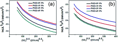 | ||
| Fig. 7 Space-charge-limited current (SCLC) fittings for (a) hole-only SCLC devices: ITO/PEDOT:PSS/blend/Au; and (b) electron-only devices with the structure Al/blend/Al. | ||
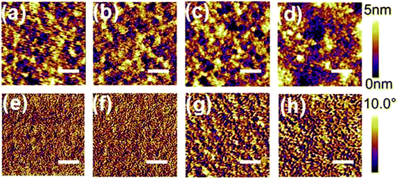
To gain more insights into the improved JSC derived from the PNDI-1F-Ph and PNDI-2F-Ph polymers, atomic force microscopy (AFM) was used to investigate the surface morphology of a surface mimicking the active layers. The obtained AFM height and phase images (2 μm × 2 μm) are shown in Fig. 8. The root mean square (RMS) roughness of the binary blends increased from 0.97 nm (PNDI-0F-Ph) to 1.17 nm (PNDI-1F-Ph), 1.30 nm (PNDI-2F-Ph), and 2.19 nm (PNDI-4F-Ph) as the number of fluorine substituents was increased. The PTB7-Th:PNDI-0F-Ph binary blend showed the minimum RMS value and smallest aggregation domains (Fig. 8a and e). In contrast, the PTB7-Th:PNDI-4F-Ph binary blend exhibited the maximum RMS value and largest aggregation domains (Fig. 8d and h) owing to the fact that this polymer had the highest coplanarity and a low solubility, which led to the formation of a poor morphology, and thus the lowest JSC. The PTB7-Th:PNDI-1F-Ph and PTB7-Th:PNDI-2F-Ph binary blends exhibited a moderate RMS value and moderate aggregation domains, which would benefit the system by producing more favorable phase-separated domains as well as more efficient exciton dissociation and charge separation, therefore leading to significantly higher JSC and PCE.44 Although the morphologies of blend films were optimized by the fluorinated polymers (PNDI-1F-Ph and PNDI-2F-Ph) according to AFM study, the FF values have not been found to be significantly affected (Table 2). There are several factors that can effectively affect FF, namely series resistance, shunt resistance and diode, and these factors interact with each other very intricately.47 Thus, a deep understanding to FF is quite difficult. FF is typically indicative of film morphology and quality, and thus besides microscopy technology, further study on phase-separated morphology of active layers via the measurement of 2D-grazing incident X-ray scattering (GIXS) or other technologies (for instant, electrochemical impedance spectroscopy) is necessary in future to give a deeper insight of the effect of fluorination on the film properties.
It should be noted that unlike the other three polymers, PNDI-1F-Ph possesses a non-symmetrical structure (Scheme 1), and also there should be isomers for this polymer depending on the F position on the phenyl ring. The detailed investigation of the correction between these structural characteristics and the properties of the materials (e.g., regioregularity) is necessary in future.
Conclusions
We have investigated the synthesis and photovoltaic properties of four fluorinated D–A polymers consisting of NDI and a fluorinated phenyl unit, in which the fluorine content of the polymer was controlled by the fluorination of the phenylene unit. The introduction of fluorine atoms was observed to cause multiple effects on the properties of the conjugated polymers, including improving their light absorption, lowering their frontier energy levels and changing their crystal properties. The polymer (PNDI-2F-Ph) with a difluorinated phenyl unit exhibited the highest PCE of 2.50% when blended with PTB7-Th. Several important points can be deduced from the present study. First, modification by fluorination of the polymer backbone can have a significant effect on the physical properties of polymers, including on light absorption, HOMO and LUMO energy levels. Second, mutual compatibility of the acceptor polymer and the donor PTB7-Th can dramatically affect the solar cell power output. In this work, fluorination provided the driving force for the phase separation of the donor/acceptor blend film, resulting in a great difference in solar cell efficiency among the devices fabricated from the different polymers. Last, to enhance solar cell performance, synergistic optimization of the polymer structure is crucial. The optimum amount of fluorine substitution should be considered for achieving high performance PSCs.Acknowledgements
The authors thank the National Basic Research Program of China (Fundamental Studies of Perovskite Solar Cells 2015CB932200), the National Natural Science Foundation of China (No. 51373076, 51303080, 91433118, and 21303081), the Science and Technology Department of Jiangsu province (No. BK20130942), and Special Funds for the Development of Strategic Emerging Industries in Shenzhen (No. JCYJ20160530184453345) for their financial support.References
- G. Yu, J. Gao, J. C. Hummelen, F. Wudl and A. J. Heeger, Science, 1995, 270, 1789 CAS.
- J. J. M. Halls, C. A. Walsh, N. C. Greenham, E. A. Marseglia, R. H. Friend, S. C. Moratti and A. B. Holmes, Nature, 1995, 376, 498 CrossRef CAS.
- J. You, L. Dou, K. Yoshimura, T. Kato, K. Ohya, T. Moriarty, K. Emery, C. C. Chen, J. Gao and G. Li, Nat. Commun., 2013, 4, 66 Search PubMed.
- Y. Liu, J. Zhao, Z. Li, M. Cheng, W. Ma, H. Hu, K. Jiang, H. Lin, H. Ade and Y. He, Nat. Commun., 2014, 5, 5293 CrossRef CAS PubMed.
- E. Taeshik, H. Ye-Jin, N. M. Murari, S. Selvam and S. A. Jenekhe, J. Am. Chem. Soc., 2013, 135, 14960 CrossRef PubMed.
- P. Cheng, L. Ye, X. Zhao, J. Hou, Y. Li and X. Zhan, Energy Environ. Sci., 2014, 7, 1351 CAS.
- W. Li, W. S. C. Roelofs, M. Turbiez, M. M. Wienk and R. A. J. Janssen, Adv. Mater., 2014, 26, 3304 CrossRef CAS PubMed.
- T. Earmme, Y. J. Hwang, S. Subramaniyan and S. A. Jenekhe, Adv. Mater., 2014, 26, 6080 CrossRef CAS PubMed.
- H. Huang, N. Zhou, R. P. Ortiz, Z. Chen, S. Loser, S. Zhang, X. Guo, J. Casado and X. Yu, Adv. Funct. Mater., 2014, 24, 2782 CrossRef CAS.
- D. Mori, H. Benten, I. Okada, H. Ohkita and S. Ito, Energy Environ. Sci., 2014, 7, 2939 CAS.
- Y. J. Hwang, B. A. E. Courtright, A. S. Ferreira, S. H. Tolbert and S. A. Jenekhe, Adv. Mater., 2015, 27, 4578 CrossRef CAS PubMed.
- J. W. Jung, J. W. Jo, C. C. Chueh, F. Liu, W. H. Jo, T. P. Russell and A. K. Y. Jen, Adv. Mater., 2015, 27, 3310 CrossRef CAS PubMed.
- Y. Hwang, T. Earmme, B. A. Courtright, F. N. Eberle and S. A. Jenekhe, J. Am. Chem. Soc., 2015, 137, 4424 CrossRef CAS PubMed.
- J. You, L. Dou, K. Yoshimura, T. Kato, K. Ohya, T. Moriarty, K. Emery, C. Chen, J. Gao and G. Li, Nat. Commun., 2013, 4, 1446 CrossRef PubMed.
- W. Li, A. Furlan, K. H. Hendriks, M. M. Wienk and R. A. Janssen, J. Am. Chem. Soc., 2013, 135, 5529 Search PubMed.
- S. Li, M. Lei, M. Lv, S. E. Watkins, Z. Tan, J. Zhu, J. Hou, X. Chen and Y. Li, Adv. Energy Mater., 2013, 3, 1569 CrossRef CAS.
- C. Cui, W. Wong and Y. Li, Energy Environ. Sci., 2014, 7, 2276 CAS.
- S. V. Bhosale, C. H. Jani and S. J. Langford, Chem. Soc. Rev., 2008, 37, 331 RSC.
- S. Sabin-Lucian and W. Frank, Angew. Chem., Int. Ed., 2014, 53, 7428 CrossRef PubMed.
- H. Yan, B. A. Collins, E. Gann, C. Wang, H. Ade and C. R. Mcneill, ACS Nano, 2011, 6, 677 CrossRef PubMed.
- M. Schubert, D. Dolfen, J. Frisch, S. Roland, R. Steyrleuthner, B. Stiller, Z. Chen, U. Scherf, N. Koch and A. Facchetti, Adv. Energy Mater., 2012, 2, 369 CrossRef CAS.
- N. Zhou, H. Lin, S. J. Lou, X. Yu, P. Guo, E. F. Manley, S. Loser, P. Hartnett, H. Huang and M. R. Wasielewski, Adv. Energy Mater., 2014, 4, 290 Search PubMed.
- M. L. Tang and Z. Bao, Chem. Mater., 2010, 23, 446 CrossRef.
- J. H. Park, E. H. Jung, J. W. Jung and W. H. Jo, Adv. Mater., 2013, 25, 2583 CrossRef CAS PubMed.
- S. Wong, M. Hong, K. Y. Jen, R. Barto and C. W. Frank, Macromolecules, 2003, 36, 8001 CrossRef CAS.
- K. Reichenbächer, H. I. Süss and J. Hulliger, Chem. Soc. Rev., 2005, 34, 22 RSC.
- F. Babudri, G. M. Farinola, F. Naso and R. Ragni, Chem. Commun., 2007, 38, 1003 RSC.
- L. Ting, X. Xin, W. Jie-Yu, L. Chen-Jiang and P. Jian, J. Am. Chem. Soc., 2014, 136, 2135 CrossRef PubMed.
- J. W. Jo, J. W. Jung, E. H. Jung, H. J. Ahn, T. Shin and W. H. Jo, Energy Environ. Sci., 2015, 8, 2427 CAS.
- H. Chen, J. Hou, S. Zhang, Y. Liang, G. Yang, Y. Yang, L. Yu, Y. Wu and G. Li, Nat. Photonics, 2009, 3, 649 CrossRef CAS.
- P. Homyak, Y. Liu, S. Ferdous, F. Liu, T. P. Russell and E. B. Coughlin, Chem. Mater., 2015, 27, 443 CrossRef CAS.
- H. Bronstein, J. M. Frost, A. Hadipour, Y. Kim, C. B. Nielsen, R. S. Ashraf, B. P. Rand, S. Watkins and I. Mcculloch, Chem. Mater., 2013, 25, 277 CrossRef CAS.
- L. Yang, J. R. Tumbleston, H. Zhou, H. Ade and W. You, Energy Environ. Sci., 2012, 6, 316 Search PubMed.
- S. Hae Jung, W. Wei, X. Tao, L. Yongye, W. Yue, L. Gang and Y. Luping, J. Am. Chem. Soc., 2011, 133, 1885 CrossRef PubMed.
- J. W. Jung and W. H. Jo, Chem. Mater., 2015, 27, 6038 CrossRef CAS.
- H. Sarker, Y. Gofer, J. G. Killian, T. O. Poehler and P. C. Searson, Synth. Met., 1998, 97, 1 CrossRef CAS.
- S. A. Jenekhe, L. Lu and M. M. Alam, Macromolecules, 2001, 34, 7315 CrossRef CAS.
- Y. Sakamoto, S. Komatsu and T. Suzuki, J. Am. Chem. Soc., 2001, 123, 4643 CrossRef CAS PubMed.
- S. C. Price, A. C. Stuart, Y. Liqiang, Z. Huaxing and Y. Wei, J. Am. Chem. Soc., 2011, 133, 4625 CrossRef CAS PubMed.
- C. J. Brabec, A. Cravino, D. Meissner, N. S. Sariciftci, T. Fromherz, M. T. Rispens, L. Sanchez and J. C. Hummelen, Adv. Funct. Mater., 2001, 11, 374 CrossRef CAS.
- A. Gadisa, M. Svensson, M. R. Andersson and O. Inganas, Appl. Phys. Lett., 2004, 84, 1609 CrossRef CAS.
- V. D. Mihailetchi, P. W. M. Blom, J. C. Hummelen and M. T. Rispens, J. Appl. Phys., 2003, 94, 6849 CrossRef CAS.
- R. A. Street, Appl. Phys. Lett., 2008, 93, 133308 CrossRef.
- M. Cheng, L. Peng, M. Wei, J. Kui, Z. Jingbo, Z. Kai, C. Zhihua, W. Zhanhua, Y. Ya and W. Jiannong, Adv. Mater., 2014, 26, 7224 CrossRef PubMed.
- N. Leclerc, P. Chávez, O. A. Ibraikulov, T. Heiser and P. Lévêque, Polymers, 2016, 8, 11 CrossRef.
- J. W. Jung, J. W. Jo, C. C. Chueh, F. Liu, W. H. Jo, T. P. Russell and A. K. Y. Jen, Adv. Mater., 2015, 27, 3310 CrossRef CAS PubMed.
- B. Qi and J. Wang, Phys. Chem. Chem. Phys., 2013, 15, 8972 RSC.
| This journal is © The Royal Society of Chemistry 2017 |

