 Open Access Article
Creative Commons Attribution 3.0 Unported Licence
Mechanistic study of NO oxidation on Cr–phthalocyanine: theoretical insight
Anchalee Junkaewa,
Jittima Meepraserta,
Bavornpon Jansang*b,
Nawee Kungwanc and
Supawadee Namuangruk *a
*a
aNational Nanotechnology Center (NANOTEC), National Science and Technology Development Agency, Pathumthani, 12120, Thailand. E-mail: supawadee@nanotec.or.th
bPTT Research and Technology Institute, PTT Public Company Limited, Phahonyothin Rd., Sanubtub, Wangnoi, Ayutthaya 13170, Thailand. E-mail: bavornpon.j@pttplc.com
cDepartment of Chemistry, Faculty of Science, Chiang Mai University, Chiang Mai 50200, Thailand
First published on 30th January 2017
Abstract
The reaction mechanisms of NO oxidation on chromium–phthalocyanine (CrPc) were elucidated using density functional theory calculations and compared with NO reduction. The results reveal that the reaction of NO oxidation on CrPc is a two-consecutive step pathway which produces NO2 as a product. The first step can proceed through competitive Langmuir–Hinshelwood (LH) and Eley–Rideal (ER) mechanisms presenting the low activation barriers (Ea) in a range of 0.1 to 0.5 eV with exothermic aspects. Moreover, the ER mechanism is found to be more feasible. In the second step, the reaction requires an Ea of 0.32 eV, which is considered as the rate determining step of the overall reaction. By comparing both NO oxidation and reduction, the results reveal that in the low O2 system, CrPc converts NO to N2 via a dimer (NO)2 mechanism whereas in the excess O2 system, it oxidizes NO to NO2 easily. Both reaction systems required very low Ea values, thus this low cost CrPc catalyst could be a candidate for NO treatment at room temperature.
1. Introduction
Nitrogen monoxide (NO) is one of the NOx compounds released from combustion engines. It can react with other reactants and form various toxic chemicals, photochemical smog and acid rain that have impact on human health and the environment.1 From these reasons, NO removal technologies are necessary. Recent NOx removal techniques have been developed based on two major technologies called NOx storage/reduction (NSR) and selective catalytic reduction (SCR).2–4 Catalytic based methods have been developed in order to improve the efficiency of NOx elimination with lower fuel consumption. Until now, NO reduction and oxidation using various catalysts have been explored by using experimental and computational tools.According to their high reactivity and catalytic efficiency, metal and bimetal catalysts have been applied for various chemical reactions.5,6 However, one of their limitations is the expensive price of metals. Therefore, other materials are used for supporting metal catalysts to reduce cost of them but yet to maintain their catalytic reactivity. For the NOx abatement technology, Pt–Ba/Al2O3 has been broadly used in the NSR technique.3 Vanadium-based catalysts have been widely used in commercials for the ammonia selective catalytic reduction (NH3-SCR) of NO, however their drawback is the toxicity of vanadium.7 To date, each of current materials and methods under investigation has its own advantages and disadvantages. Undoubtedly, improvement of high catalytic efficiency associated with a reasonable price is still a main challenge in the commercial NOx removal technology.
Regarding the discovery of the graphene sheet, other two dimensional (2D) materials have been received more attention and explored extensively these days. Metal-free and metal-supported 2D materials such as SiC,8 silicene,9 metal–graphene,10 metal–graphene oxide (metal–GO)11 and metal–boron nitride (metal–BN)12,13 have been searched for using as adsorbates and catalysts in air treatment applications. Among those materials, 2D organometallic materials such as metal–phthalocyanines (MPcs) and metal–porphyrins (MPors), have been successfully synthesized by embedding metal species to the 2D-conjugated polymers.14–18 These materials are controllable dispersed of central metal, which can prevent metal clustering. Additionally, their properties are tunable when replacing metals by other elements.19,20 The embedded metal is highly stable preventing the aggregation into metal cluster which is one of the problems of using metal catalysts. Moreover, this structural diversity expands a wide range of usages. They have been proposed as catalysts in various reactions including the catalytic CO and NOx treatment technologies.21,22 For instance, the decomposition of N2O over metal–porphyrins (metal: Ti, Cr, Fe, Co, Ni, Cu and Zn) were elucidated by using DFT calculations.22 The result indicated that the TiPor is a promising catalyst for decomposing N2O into N2 and O2 products. Additionally, many Pc-based materials have been explored for NOx sensing by experimental and computational studies. For example, NiPc was investigated for NO23,24 and FePc,25 TiOPc, PbPc26,27 and CuPc28–30 were studied for detecting NO2.
In 2014, Li and Sun31 simulated the CO and O2 adsorption on transition metal embedded Pc sheets (MPc, M = Cr, Mn, Fe, Co, Ni). According their adsorption results, MnPc, CrPc and FePc revealed the good adsorption ability toward the O2 and CO molecules. They found that CrPc has the superior catalytic property for the CO oxidation. For the NO decomposition, the direct NO dissociation, which is breaking N–O bond and producing N and O atoms on surfaces, requires very high Ea of 2.52 eV over CrPc32 and more than 3.0 eV over Si-doped graphene.33 Recently, we have proposed that CrPc is the potential catalyst for the NO reduction by forming (NO)2 dimer.32 Along with the exothermic aspect, the Ea of the rate-determining step for the most favorable path of the NO reduction over CrPC is only 0.35 eV. This aspect implied that CrPc is feasible for reducing NO at low temperature.32 However, this prediction was based on the absence of O2 which is one of the main components in the gas mixture. In flue gas or exhaust gas mixture, O2 is believed to be involved in the reaction of NO decomposition. Thus, we expanded our study by considering the involvement of O2 in the reaction.
In this study, we proposed that NO is oxidized by O2 on the CrPc catalyst. Two major mechanisms called Eley–Rideal (ER) and Langmuir–Hinshelwood (LH) mechanisms were theoretically investigated. The rate-determining steps were intensively determined from the activation energy (Ea) calculations. The obtained results from this NO oxidation is compared and discussed with the NO reduction reported in our previous work.32 The catalytic reactivity of other materials for similar reactions were also discussed.
2. Method
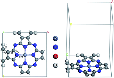
All calculations were carried out in a framework of the spin polarization DFT method using a generalized gradient approximation (GGA) of Perdew–Burke–Ernzerholf (PBE) functional.34 A double numerical plus polarization (DNP) basis set35 was used with the real space global orbital cutoff radius as 4.8 Å. A smearing of electronic occupations was set as 5.0 × 10⁻³ Ha. An energy threshold was 1.0 × 10⁻⁵ Ha, while a force threshold was 2.0 × 10⁻³ Ha Å−1. Self-consistent field (SCF) calculations were carried out with a convergence criterion of 1.0 × 10⁻⁵ Ha. All electron calculations were performed for the C, N, O, and H atoms, and a relativistic effect included effective potential was used to represent core electrons of the Cr atom. All atoms in the system were allowed to relax during the geometry optimizations. The z-direction was set as the perpendicular to the plane of the CrPc monolayer while the x- and y-directions were in parallel, see Fig. 1. The supercell length in the z-direction was set to 15 Å to avoid the artificial interaction of periodic images. The Brillouin zone sampling was 5 × 5 × 1 k-points. A method for transition state (TS) search was employed by a linear synchronous transit (LST) method, followed by repeated conjugated gradient (CG) refinements, and then quadratic synchronous transit (QST) maximizations36 and repeated CG refinements until the TS is located. Finally, a nudged elastic band (NEB) method37 was performed to obtain a minimum energy pathway (MEP). The vibrational frequency calculation was performed on the obtained TS structure to ensure that it has only one imaginary frequency corresponding to the reaction coordinate. The Hirshfeld charge was used to explain charge on atoms and charge density difference between the adsorbate and CrPc in the adsorption complexes. All calculations were performed on the Dmol3 module35,38 implemented in Material Studio 8.0.Based on our previous report,32 the stable sites of NO, O2 as well as the related reactive species were stable on the Cr metal site of the CrPc surface. In this work, we reconsidered all possible configurations of each gas molecules on CrPc and the most preferable site and configuration of each gas adsorption are presented. The adsorption energies (Ead) of NO, O2, and N2O on the CrPc catalyst can be calculated by the following equation:
| Ead = Egas/CrPc − ECrPc − Egas |
3. Results
The optimized CrPc monolayer with the bond lengths is illustrated in Fig. 1. The bond lengths between the central Cr atom and each neighboring N atom are equivalent at 1.98 Å, which is similar to the value of 2.001 Å calculated by using GGA + U method (the U parameter is entered to GGA calculation to treat the strong on-site Coulomb interaction of localized d-electrons of Cr).39 The reaction of NO oxidation to produce NO2 can be explained by 2NO + O2 → 2NO2. In the first part, the adsorption of O2, NO and NO2 on CrPc are discussed in order to understand the interactions between the reactant or product compounds and the catalyst. In the second part, PES diagrams of the possible mechanisms are compared to find the most favorable pathway.3.1 Gas adsorption on CrPc
Based on types of gases involved in the NO oxidation, adsorbed gases over the CrPc sheets, which are O2/CrPc, NO/CrPc and NO2/CrPc were calculated. In the previous study,32 we had carefully studied the possible adsorption configurations of NO on CrPc. It was found that a NO prefers the N-bound adsorption mode in which the terminal N atom of NO has a strong bond with the Cr site. To compare with other gas species, the calculated Ead values, charges and corresponding structural parameters are summarized in Table 1. The bond lengths of isolated gases are given in the parentheses. From the calculated Ead, the order of adsorption strength is NO/CrPc (−2.07 eV) > NO2/CrPc (−1.28 eV) > O2/CrPc (−1.13 eV). All studied gases have the strong chemical bonds with the CrPc substrate. Additionally, the NO reveals the stronger binding strength with CrPc compared with NO/MnPc (Ead = −1.73 eV), NO/CoPc (Ead = −1.55 eV) and NO/FePc (Ead = −1.90 eV) systems reported in literature.21| Adsorption complex | Ead (eV) | Structural parameter | |
|---|---|---|---|
| Bond | Length (Å) | ||
| O2/CrPc | −1.13 | Cr–O | 1.85 |
| O–O | 1.40 (1.23) | ||
| NO/CrPc32 | −2.07 | Cr–N | 1.67 |
| NO | 1.18 (1.16) | ||
| NO2/CrPc | −1.28 | Cr–N | 2.00 |
| NO | 1.23 (1.21) | ||
The O2/CrPc presents the parallel adsorption configuration with the Ead of −1.13 eV. The oxygen molecule is activated and the O–O bond is elongated to be 1.40 Å compared with that of the isolated O2 molecule (1.23 Å), which is in good agreement with other studies.31 For the NO2/CrPc, NO2 attaches to the central Cr atom with the distance of 2.00 Å and the Ead of −1.28 eV. This interaction is much stronger than NO2/CuPc which has the Ead of −0.40 eV.40 Comparing with isolated gases, the adsorbed O–O bond is increased about 0.17 Å, while bonds of adsorbed NO and NO2 are less lengthened in range of 0.02–0.03 Å.
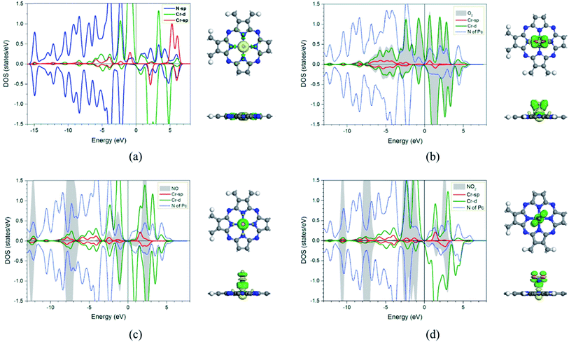
In addition, the electronic charge properties of the pre-adsorbed and gas-adsorbed CrPc are clarified to give a deeper understanding. The density of state (DOS) and electron density difference of the bare CrPc, O2/CrPc, NO/CrPc and NO2/CrPc systems are illustrated in Fig. 2a–d, respectively. For the DOS analysis (in the left panel), the blue, green and red peaks present the partial DOS of N-sp, Cr-d and Cr-sp orbitals of CrPc, correspondingly. In gas-adsorbed systems, the grey peaks depict the partial DOS of the adsorbed gases. The Fermi level (Ef) is set to zero eV. For the charge difference analysis (in the right panel), the green and yellow isosurfaces signify the electron density accumulation and depletion, respectively. In each system, the charge difference analysis is illustrated in both top- and side-views.
In Fig. 2a, the partial DOS of the bare CrPc are projected. The interaction between the central Cr atom and its neighboring N atoms is indicated by the overlapped peaks of the DOS plot in the right panel. For the partial DOS of Cr, the asymmetric peaks of the spin-up and spin-down components indicate the magnetic characteristic of the metal site. The charge difference explains that the electrons are reduced at the Cr site while they are accumulated between Cr and N atoms. This feature also relates to the partial charge values, which are +0.96 e of Cr atom and −0.62 e of the neighboring N atom, reported in the previous study.22
For the activated O2 on CrPc, the side-on interaction of O2 on CrPc is dominated by the overlapping of the LUMO (2π*) of O2 and the highest occupied molecular orbital (HOMO-3) of CrPc.31 This hybridization feature can be observed from the overlapping of those grey peaks of O orbitals and green peaks of Cr-d orbitals as shown in the left panel of Fig. 2b. The charge difference of O2/CrPc is displayed in the right panel. At the Cr site, the electron density on one side of the CrPc sheet is reduced while the accumulation can be observed on another side. This characteristic indicates the bonding between Cr and O atoms. The accumulated electron regions are presented by the green basin around oxygens.
The interaction between NO and CrPc can be described by the symmetrically interaction between the lowest unoccupied molecular orbitals (LUMO) of CrPc on the dπ and the 2π* orbitals of NO.32 The HOMO–LUMO gap is wider as compared to that of the bare CrPc sheet. A strong hybridization in both spin-up and spin-down states of the Cr-d and NO orbitals is clearly demonstrated in Fig. 2c. Especially, in the spin-down states the 2π* orbital of NO molecule is dominantly occupied. Considering the interaction between CrPc and NO, the electron accumulation, which is the green region of the charge difference analysis, exists between the Cr and N atoms. On the other hand, the electron density at the N–O bond is decreased. Likewise, the interaction between NO2 and CrPc can be observed from the DOS and charge difference analyses as illustrated in Fig. 2d. The hybridization between the valence states of NO2 and Cr is dominated for their bonding. Similar to other cases, the accumulation of electron density between the Cr and the adsorbate molecule can be observed from the charge differences.
3.2 Mechanisms of NO oxidation on CrPc
Due to the much stronger adsorption energy of NO than O2, NO will be fully occupied on the Cr site if concentrations of O2, NO and Cr active site in the system are equivalent. It is simply predicted that the NO reduction would proceed in this case.32 On the other hand, if O2 is abundant in the system, O2 and NO could be competitively occupied on the Cr active site; the NO oxidation by O2 will further proceed. The detailed mechanisms of NO oxidation on CrPc are given in this section.The overall reaction of NO oxidation is 2NO + O2 → 2NO2. The proposed mechanisms of NO oxidation on CrPc are composed of following individual steps:
Step 1: the first NO oxidation to produce the first NO2 by
 | (1.1) |
 | (1.2) |
 | (1.3) |
 | (1.4) |
| OONO*–CrPc → O*–CrPc + NO2 | (1.5) |
Step 2: the second NO oxidation to produce the second NO2 by
 | (2.1) |
 | (2.2) |
 . In this work, two possible mechanisms called ER and LH mechanisms are elucidated for the first NO oxidation step. The ER pathway can be described by eqn (1.1) to (1.3). The LH mechanism is explained by eqn (1.4) to (1.5).
3.2.1.1 ER mechanism. In the O2 abundant system, O2 molecule is adsorbed and activated on the catalyst first. This elementary step can be described by eqn (1.1). As presented in the previous section, the O2 molecule is simultaneously adsorbed on the CrPc catalyst with the Ead of −1.13 eV. Next, NO interacts with the pre-adsorbed
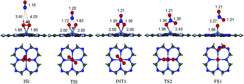
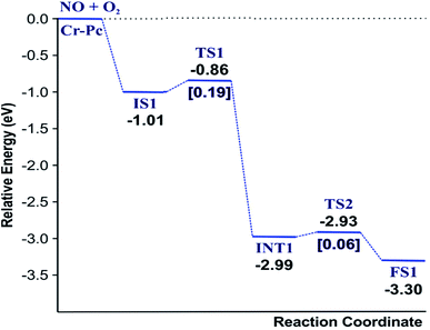
 to form the first NO2 molecule. The structures and corresponding energy profile of the ER mechanism are depicted in Fig. 3 and 4, respectively. The NO molecule interacts with the activated
  (IS1) by inserting between two O atoms and forms the
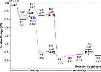
  intermediate (INT1) on the Cr atom. When IS1 transforms to INT1, the N initiates bonds with O atoms while the O–O and O–Cr bonds are lengthened from 1.40 to 2.12 Å and 1.85 to 2.00 Å, respectively. This path is the exothermic process which is required the small Ea of 0.19 eV. The transition state (TS1) is confirmed by a single negative vibrational frequency of 167.27i cm−1. Next, the successive step proceeds through the INT1, transition state (TS2), and final state (FS1). The TS2 and the FS1 are illustrated in Fig. 3. The Ea value is only 0.06 eV, which is less than the previous step. At the TS2 state, elongation of one Cr–O bond (2.43 Å) and O–N bond (1.34 Å) are observed. This transition state is confirmed by the frequency of 158.15i cm−1. At the final state, those bonds are completely dissociated to release the first NO2 molecule. One oxygen atom remains on CrPC and it will interact with the second NO molecule in the further step. According to the relative energy, FS1 is very thermodynamically stable than IS1. It is noted that the product state of each elementary step has lower relative energy than its preceding state. The reaction proceeds through the very small Ea values and large exothermic reaction. This feature indicates that this ER mechanism is kinetically and thermodynamically favorable reaction.
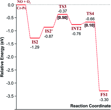
3.2.1.2 LH mechanism. The structures and energy profile of the LH mechanism are expressed in Fig. 5 and 6, respectively. In LH mechanism, O2 and NO are initially co-adsorbed on CrPc as shown in Fig. 5. At the initial step, there are two co-adsorbed configurations which are IS2 and IS2′ (see Fig. 5). Both O atoms bind with the Cr atom in the IS2 form, while only one O atom is attached with the Cr atom in IS2′ form. The energy difference of 0.43 eV is for transforming IS2 to IS2′. Then, IS2′ forms the peroxide-like O–N–O–O intermediate (INT2) via the transition state (TS3). This path is the endothermic process requiring the Ea value of 0.50 eV. In the following step, NO2 is released and one O atom remains on the catalyst. This step occurs through INT2, TS4 and FS1, sequentially. The O–O bond starts rupturing by lengthening bond from 1.44 Å in INT2 to be 1.60 Å in TS4. The small Ea of 0.10 eV is required to overcome this barrier. This is the exothermic process. The vibrational frequencies of TS3 and TS4 are −302.23i and −621.07i cm−1, respectively. Finally, the first NO2 product is released and one O atom remains on the catalyst.
As a result, low energy barriers can be observed in both mechanisms. The Ea energies are required in range of 0.1 to 0.2 eV and 0.1 to 0.5 for the ER and LH mechanisms, respectively. However, the ER pathway is the preference path due to its lower Ea of the rate limiting step and its lower relative energies of intermediate states compared to those of the LH pathway.
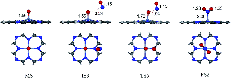
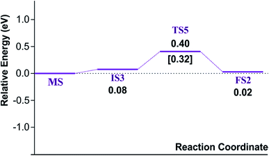
Finally, the energy profiles of all steps are compared in Fig. 9. In summary, the first NO oxidation step requires low energy to proceed. This step prefers the ER mechanism with the Ea of 0.19 eV for the rate-determining step and the exothermic aspect. Although, the LH mechanism has higher Ea values than the ER mechanism, it still has the moderate Ea with the exothermicity. For forming the second NO2, the Ea is slightly higher than the first NO2 formation with slightly exothermic feature. The oxidation can occur easily due to low activation energy pathway. Our result suggested that the overall reaction pathways of NO oxidation on CrPc are thermodynamically and kinetically favorable. Thus, this CrPc monolayer is one of potential catalysts for the NO oxidation at low temperature.
Considering the calculated Ea values of NO removal processes catalyzed by CrPc catalyst in Table 2, the NO oxidation by O2 studied in this work tends to occur slightly easier than the NO reduction by NO from our previous work.32 The calculated Ea values of the rate determining steps are 0.32 eV for the oxidation and 0.35 eV for the reduction, respectively. These small Ea values indicate the high activity of CrPc for both reactions at room temperature or even lower. Moreover, the rate-limiting steps and the corresponding reaction barriers for the NO and CO decomposition reactions on the selected 2D-based catalysts from literatures are summarized in Table 2. Comparing with CO oxidation on CrPc reported in literature,31 the NO oxidation occurs easier than the CO oxidation. Considering other 2D-materials, their catalytic reactivities presented by the calculated Ea values tend to lower than that of CrPc for the NO oxidation and reduction. Among the 2D-materials reported in literature the CrPc material is, therefore, a candidate catalysts for low-temperature NOx removal.
| Catalyst | Reaction steps | Ea (eV) |
|---|---|---|
| CrPc (this work) | NO + O2 → NO2 + O* | 0.19 |
 |
0.32 | |
| CrPc32 | NO + NO → N2O + O* | 0.35 |
| CrPc31 | CO + O2 → CO2 + O* | 0.55 |
| CO + O* → CO2 | 0.46 | |
| Pt/TiPc41 | CO + O2 → CO2 + O* | 0.55 |
| Si/graphene42 | CO + O2 → CO2 + O* | 0.43 |
| CO + O* → CO2 | 0.07 | |
| SiC43 | NO + NO → N2O | 0.72 |
| Silicene44 | N2O → N2 + O* | 0.45 |
| Si/graphene33 | NO + NO → N2O + O* | 0.46 |
| Pt/graphene10 | CO + O2 → CO2 + O* | 0.15, 0.35 |
| CO + O* → CO2 | 0.46 | |
| N/Graphene (NG)45 | (NO)2 → N2O + O* | 0.70 |
| N2O + O + NO → N2O + NO2 | 0.27 | |
| N2O + N2 → N2 + O* | 0.05 | |
| NO + O* → NO2 | 0.16 | |
| Pt/oxidized graphene46 | CO + O2 → CO2 + O* | 0.76 |
| CO + O* → CO2 | 0.04 |
4. Conclusion
The detailed mechanisms of NO oxidation on the CrPc sheet were studied by performing the DFT calculations with PBE functional. There are two oxidation steps proposed in this study. The first NO oxidation begins with the reaction between NO and O2 over CrPc to produce NO2 molecule and one O atom attached on Cr. In this step, the simulated ER and LH mechanisms present the competitive nature with comparable Ea and the exothermic aspect. As a result, the ER pathway, which is more favorable pathway, has lower Ea than LH pathway about 0.3 eV. Based on these energetic aspects, the ER mechanism is the kinetically and thermodynamically preference pathway for the first NO2 production. The second NO oxidation step (i.e. NO + O* → NO2) reveals the Ea of 0.32 eV which is considered as the rate determining step of the overall reaction. Comparison of the NO oxidation in this work with the NO reduction in our previous report,30 the NO adsorption is two-fold stronger than the O2 indicating the NO molecule would be easily occupied on the Cr active site to follow the NO reduction. Under the O2 abundant condition, the NO oxidation by O2 would be competitive. However, both reactions proceed with low Ea (<0.35 eV) and high exothermicity, indicating that CrPc is the active catalyst for NO removal at room temperature or even lower.Acknowledgements
The authors thank the National Nanotechnology Center (NANOTEC) through the Flagship “Clean Air” program for the financial support. The computational resources at PTT Research and Technology Institute, Wangnoi, Thailand is also acknowledged.References
- A. Fritz and V. Pitchon, Appl. Catal., B, 1997, 13(1), 1 CrossRef CAS.
- W. S. Epling, L. E. Campbell, A. Yezerets, N. W. Currier and J. E. Parks, Catal. Rev.: Sci. Eng., 2004, 46(2), 163 Search PubMed.
- S. Roy and A. Baiker, Chem. Rev., 2009, 109(9), 4054 CrossRef CAS PubMed.
- J. Li, H. Chang, L. Ma, J. Hao and R. T. Yang, Catal. Today, 2011, 175(1), 147 CrossRef CAS.
- W. Yu, M. D. Porosoff and J. G. Chen, Chem. Rev., 2012, 112(11), 5780 CrossRef CAS PubMed.
- N. Lopez and J. K. Nørskov, J. Am. Chem. Soc., 2002, 124(38), 11262 CrossRef CAS PubMed.
- C. Ciardelli, I. Nova, E. Tronconi, D. Chatterjee, T. Burkhardt and M. Weibel, Chem. Eng. Sci., 2007, 62(18–20), 5001 CrossRef CAS.
- J. W. Feng, Y. J. Liu and J. X. Zhao, J. Mol. Graph. Model., 2015, 60, 132 CrossRef CAS PubMed.
- X. Xu, J. Li, X. Zhang, H. Xu, Z.-F. Ke and C. Zhao, RSC Adv., 2015, 5(28), 22135 RSC.
- X. Liu, Y. Sui, T. Duan, C. Meng and Y. Hanb, Phys. Chem. Chem. Phys., 2014, 16, 23584 RSC.
- C. Chen, K. Xu, X. Ji, L. Miao and J. Jiang, Phys. Chem. Chem. Phys., 2014, 16(22), 11031 RSC.
- X. Liu, T. Duan, C. Meng and Y. Han, RSC Adv., 2015, 5(14), 10452 RSC.
- K. Mao, L. Li, W. Zhang, Y. Pei, X. C. Zeng, X. Wu and J. Yang, Sci. Rep., 2014, 4, 5441 CrossRef CAS PubMed.
- Y. Bai, F. Buchner, M. T. Wendahl, I. Kellner, A. Bayer, H.-P. Steinrück, H. Marbach and J. M. Gottfried, J. Phys. Chem. C, 2008, 112(15), 6087 CAS.
- C.-L. Song, Y.-L. Wang, Y.-X. Ning, J.-F. Jia, X. Chen, B. Sun, P. Zhang, Q.-K. Xue and X. Ma, J. Am. Chem. Soc., 2010, 132(5), 1456 CrossRef CAS PubMed.
- A. B. Sorokin, Chem. Rev., 2013, 113(10), 8152 CrossRef CAS PubMed.
- G. Zhu and Q. Sun, Comput. Mater. Sci., 2016, 112, 492 CrossRef CAS.
- G. Zhu, Y. Li, H. Zhu, H. Su, S. H. Chan and Q. Sun, ACS Catal., 2016, 6(9), 6294 CrossRef CAS.
- M. Abel, S. Clair, O. Ourdjini, M. Mossoyan and L. Porte, J. Am. Chem. Soc., 2011, 133(5), 1203 CrossRef CAS PubMed.
- A. Sperl, J. Kröger and R. Berndt, J. Am. Chem. Soc., 2011, 133(29), 11007 CrossRef CAS PubMed.
- T. Q. Nguyen, M. C. S. Escaño and H. Kasai, J. Phys. Chem. B, 2010, 114(31), 10017 CrossRef CAS PubMed.
- P. Maitarad, S. Namuangruk, D. Zhang, L. Shi, H. Li, L. Huang, B. Boekfa and M. Ehara, Environ. Sci. Technol., 2014, 48(12), 7101 CrossRef CAS PubMed.
- C. J. Liu, J. J. Shih and Y. H. Ju, Sens. Actuators, B, 2004, 99(2–3), 344 CrossRef CAS.
- K.-C. Ho and Y.-H. Tsou, Sens. Actuators, B, 2001, 77(1–2), 253 CrossRef CAS.
- J. K. O'Rourke, J. S. Brooks, N. A. Bell, J. Cawley and S. C. Thorpe, Sens. Actuators, B, 1993, 14(1), 690 CrossRef.
- C. J. Liu, J. C. Hsieh and Y. H. Ju, J. Vac. Sci. Technol., A, 1996, 14(3), 7536 Search PubMed.
- J. C. Hsieh, C. J. Liu and Y. H. Ju, Thin Solid Films, 1998, 322(1–2), 98 CrossRef CAS.
- Y.-L. Lee, C.-Y. Sheu and R.-H. Hsiao, Sens. Actuators, B, 2004, 99(2–3), 281 CrossRef CAS.
- M. I. Newton, T. K. H. Starke, M. R. Willis and G. McHale, Sens. Actuators, B, 2000, 67(3), 307 CrossRef CAS.
- C. Park, D. Hyun Yun, S.-T. Kim and Y. Woo Park, Sens. Actuators, B, 1996, 30(1), 23 CrossRef CAS.
- Y. Li and Q. Sun, Sci. Rep., 2014, 4, 4098 Search PubMed.
- J. Meeprasert, A. Junkaew, N. Kungwan, B. Jansang and S. Namuangruk, RSC Adv., 2016, 6(25), 20500 RSC.
- Y. Chen, Y.-J. Liu, H.-X. Wang, J.-X. Zhao, Q.-H. Cai, X.-Z. Wang and Y.-h. Ding, ACS Appl. Mater. Interfaces, 2013, 5(13), 5994 CAS.
- J. P. Perdew, K. Burke and M. Ernzerhof, Phys. Rev. Lett., 1996, 77(18), 3865 CrossRef CAS PubMed.
- B. Delley, J. Chem. Phys., 2000, 113(18), 7756 CrossRef CAS.
- T. A. Halgren and W. N. Lipscomb, Chem. Phys. Lett., 1977, 49(2), 225 CrossRef CAS.
- G. Henkelman and H. Jónsson, J. Chem. Phys., 2000, 113(22), 9978 CrossRef CAS.
- B. Delley, J. Chem. Phys., 1990, 92(1), 508 CrossRef CAS.
- J. Zhou and Q. Sun, J. Am. Chem. Soc., 2011, 133(38), 15113 CrossRef CAS PubMed.
- L. Lozzi, S. Picozzi, S. Santucci, C. Cantalini and B. Delley, J. Electron Spectrosc. Relat. Phenom., 2004, 137–140, 101 CrossRef CAS.
- X. F. Chen, J. M. Yan and Q. Jiang, J. Phys. Chem. C, 2014, 118(4), 2122 CAS.
- Y. Tang, Z. Liu, X. Dai, Z. Yang, W. Chen, D. Ma and Z. Lu, Appl. Surf. Sci., 2014, 308, 402 CrossRef CAS.
- J. W. Feng, Y. J. Liu and J. X. Zhao, J. Mol. Graphics Modell., 2015, 60, 132 CrossRef CAS PubMed.
- X. Xu, J. Li, X. Zhang, H. Xu, Z.-F. Ke and C. Zhao, RSC Adv., 2015, 5(28), 22135 RSC.
- X. Zhang, Z. Lu, Y. Tang, Z. Fu, D. Ma and Z. Yang, Phys. Chem. Chem. Phys., 2014, 16(38), 20561 RSC.
- Y. Tang, X. Dai, Z. Yang, L. Pan, W. Chen, D. Ma and Z. Lu, Phys. Chem. Chem. Phys., 2014, 16(17), 7887 RSC.
| This journal is © The Royal Society of Chemistry 2017 |

