 Open Access Article
Creative Commons Attribution 3.0 Unported Licence
Fabrication and multifunctional properties of polyimide based hierarchical composites with in situ grown carbon nanotubes
Chao Su a,
Feng Xuea,
Tongsheng Li*a,
Yuanshi Xin
 a,
Mingming Wanga,
Jia Tangb and
Yuning Mab
aState Key Laboratory of Molecular Engineering of Polymers, Department of Macromolecular Science, Fudan University, Shanghai 200433, China. E-mail: lits_fudan@sina.com; Fax: +86-21-51630401; Tel: +86-21-51630401
bAdvanced Materials Institute, Shandong Academy of Sciences, Jinan, Shandong 250014, China
First published on 7th June 2017
Abstract
Polyimide (PI) based hierarchical composites reinforced with carbon nanotubes (CNTs) directly grown on the surface of carbon fabric were prepared. The growth morphology and other characteristics of the CNTs were analyzed by detailed techniques, which proved the growth of CNTs on the surface of carbon fiber (CF). The CNT–CF/PI composites with a growth time of 40 min showed an increase of 33% in flexural strength, 42% in flexural modulus, 17 °C in the temperature at 5 wt% of weight loss, 27 °C in glass transition temperature and five orders of magnitude in through-thickness electrical conductivity as compared to those of conventional carbon fabric reinforced polyimide composites. The significant improvement of the comprehensive properties of the hierarchical composites can be attributed to the stiffer CNTs-reinforced matrix, the enhanced fiber–matrix interfacial adhesion and/or the strong synergetic effect between the nano and micro-scale fillers. The enhancement mechanism of the hierarchical composites on various different scales was also discussed in detail. It is believed that the present study can provide broad application potential in polyimide-based polymer composites and other types of high performance thermoplastic systems.
1. Introduction
In recent years, continuous fiber reinforced polymer composites have been widely used as advanced structural composite materials in various industries,1–5 such as aerospace, sporting equipment, automotive, civil and marine engineering, due to their light weight and superior mechanical properties, while being environmentally or chemically resistant. Among these materials, carbon fiber reinforced polyimide composites have excellent comprehensive performances, owing to their high strength-to-weight ratio, excellent tribological properties, good chemical resistance and outstanding heat resistance.6–8 Usually, high-performance carbon fiber composites are fabricated with carbon fabric (CF) as reinforcement material, which have the better properties than those of the short carbon fiber reinforced composites. Because the unique fiber architectures in the laminated composites, the fiber-dependent properties, such as tensile strength and Young's modulus, are usually very high. However, the matrix-dominated properties, such as flexural and interlaminar shear strength, are much worse than the in-plane properties, which significantly restricted their use in critical structural applications.9–11 The reason is that delamination between laminas caused severe reduction in the in-plane stiffness and strength. The weak fiber–matrix interface and the brittleness of many polymer matrices led to a catastrophic failure of the whole structure. Hence, both academia and industry have focused their attention on improving the through-thickness properties of laminated composites. Many researchers found that the most effective way is improving the surface activity of the fibers and thus improving the interfacial bonding strength between fiber and matrix by fiber surface treatments.12–18 In these methods, carbon nanotubes (CNTs) directly grafting19 or growing on the surface of fiber have been attracting the researcher's interests because it can not only improve the surface activity of the fibers and also fundamentally solve the problem of agglomeration of carbon nanotubes. This method shows a lot of advantages compared to other methods. A large number of studies have already testified that the CNTs could grow well on the surface of fibers, such as carbon,20–22 alumina23 or SiC24 fiber. Wang25 prepared the hierarchical CNTs/CF reinforcement by the chemical vapor deposition (CVD) method and suggested that the CNTs/CF grafting force was more than 5 μN, and CNTs/CF attachment can sustain the fracture of the CNTs, which was expected to be contributed to the improvement of the interfacial properties. The wettability between CNTs grafted fibers and multiple polar matrices can be enhanced by introducing oxygen containing functional groups onto the surface of CNTs in atmosphere.26 Thus, it is beneficial to the molten epoxy resin and other polymer components can penetrating into the CNT layers easily by capillary forces.27,28 Different micromechanical approaches have been used to test the interfacial properties of single CNT-grafted carbon fiber model composites, such as the single fiber pull-out and push-out,26 microdroplet debond29 or fragmentation tests.30–32 Zhang29 et al. used single fiber-microdroplet tensile test to measure the interfacial shearing strength (IFSS) of a composite with an epoxy matrix and a novel CNT/CF multi-scale reinforcement, results showed that its IFSS was as high as 160.55 MPa, which was 150% higher than that of the as-received T300 fiber composite. Single-fiber fragmentation tests revealed that CVD processing significantly reduces the ultimate tensile strength of the fiber by an average of 37% in the case of the radially aligned MWCNTs and by 30% in the case of randomly oriented MWCNTs compared with commercially sized and unsized fibers. All these results suggested that the feasibility of reinforcing conventional carbon fiber composites by growing carbon nanotubes (CNTs) onto the fiber surface.Many investigations have indicated that grown CNTs onto conventional fiber surfaces could help to improve fiber surface area, create mechanical interlocking and/or local stiffening at the fiber/matrix interface, and improve stress transfer and interfacial properties. Furthermore, this method also could improve the CNT loads and alleviate the issues that are related to agglomeration.33 The polymer matrix can be reinforced by CNTs, thus improving delamination resistance and through-thickness of the composites.20 Veedu24 proposed an approach for interlaminar reinforcement of multiscale hybrid composites by CNTs forests directly grown on SiC woven fabrics, via CVD method. The results showed an improvement of 348% and 54%, in Mode I and Mode II fracture toughness tests, respectively, over unreinforced composites. The increase in the interlaminar fracture toughness was attributed to the bridging of plies by CNT forests. The study also showed an increase of 140% in tensile strength, 5% in Young's modulus and 424% in toughness. These results suggested that the in-plane properties were not compromised; they were improved, instead. Moreover, the consistent improvement of electrical23,34,35 and thermal24 properties was also observed, indicating that the CNTs provided 3D conducting paths throughout the composite structures. However, until to date, although many studies have been published concerning thermoset resins based hierarchical composites, few investigations have investigated thermoplastic resin matrix.36,37 Moreover, a limited number of studies has focused on the high-performance engineering plastics, such as polyphenylene sulfide, polyimide, poly(benzamide), polyethersulfone and polyetherimide.
Considering all the above, an effective approach to fabricate hierarchical CNT–CF/PI composite via a two-stage process was proposed in this article: (1) the CNTs are directly grown on the surface of the carbon fabric by the CVD method, and (2) these so called hybrid preforms will be used as reinforcement material within a polyimide resin to develop the CNT–CF hybrid composites. The experimental results showed that the growth strategy is efficient and PI can infiltrate the CNTs well. As a result, mechanical interlocking and local stiffening at the fibre/matrix interface was created and which can improve stress transfer and interfacial properties. The laminated composites composed of microscale (carbon fiber) with nanoscale constituents (CNTs) allowed the uniform dispersion of high volume fraction of CNTs throughout the composite, without undesired agglomeration, as occurred in the case of the neat CNT/polymer composites. The CNTs can also penetrate into the matrix-rich regions through the individual fibers and layers of laminated composites thus significantly improved the electrical conductivity, mechanical and thermal properties of the CNT–CF/PI composites. In order to in-depth understand the related enhancement mechanism, the multiscale composites were divided into various different scales, which were discussed in detail.
2. Experimental section
2.1. Materials
Carbon fabric fabricated by T300 carbon fiber was purchased from Shanghai Institute of Chemical Fiber, China. Bisphenol-A dianhydride (BPADA) was purchased from Shanghai research institute of synthetic resins (Shanghai, China). 4,4′-Oxidianiline (4,4′-ODA), N,N-dimethylformamide (DMF), FeCl2·4H2O were all reagent grade and provided by Sinopharm Group Chemical Reagent Co., Ltd. (Shanghai, China).2.2. Coating of catalyst on the carbon fabric surface
The coating of catalyst on the carbon fabric surface is the most critical step of the overall process of direct growth of CNTs on carbon fibers. A very homogeneous coating is essential in order to get a uniform growth of CNTs on the carbon fabric surface. A method of incipient wetness technique was used to deposit catalyst particles on the carbon fabric. Initially, the carbon fabric was heat treated in an oven, at 380 °C for 120 min, in order to remove the sizing agent on the surface of the carbon fabric, followed by boiling in distilled water for 10 min and washing with acetone. After that, a nitric–sulphuric acid solution (VH2SO4![[thin space (1/6-em)]](https://www.rsc.org/images/entities/char_2009.gif) :
:![[thin space (1/6-em)]](https://www.rsc.org/images/entities/char_2009.gif) VHNO3 = 3
VHNO3 = 3![[thin space (1/6-em)]](https://www.rsc.org/images/entities/char_2009.gif) :
:![[thin space (1/6-em)]](https://www.rsc.org/images/entities/char_2009.gif) 1) was applied to the CF in order to produce the polar surface groups, particularly the carboxylic group. Then the carbon fabric was washed with plenty of water. The acid solution was used to improve the wettability of the fibers by treated with coating solution so that help to bind or stabilize the catalyst particles. Then, the acid-treated carbon fabric was immersed in FeCl2·4H2O solution (dissolved in deionized water, 0.05 mol L−1) for approximately 12 h. Subsequently, the carbon fabric was taken out of the solution and dried in an oven at 80 °C for 2 h.
1) was applied to the CF in order to produce the polar surface groups, particularly the carboxylic group. Then the carbon fabric was washed with plenty of water. The acid solution was used to improve the wettability of the fibers by treated with coating solution so that help to bind or stabilize the catalyst particles. Then, the acid-treated carbon fabric was immersed in FeCl2·4H2O solution (dissolved in deionized water, 0.05 mol L−1) for approximately 12 h. Subsequently, the carbon fabric was taken out of the solution and dried in an oven at 80 °C for 2 h.
2.3. CNT growth process
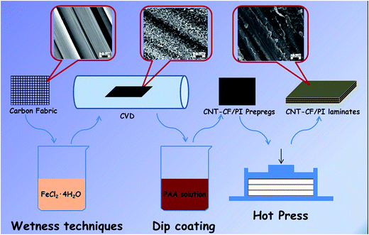
The growth of CNTs on carbon fabric was performed via CVD method. The catalyst-coated carbon fabric was placed inside a corundum reactor tube furnace in the isothermal heating zone. The furnace was initially purged with argon (Ar, 400 sccm) and heated to 740 °C at a rate of 50 °C min−1. In order to convert the FeCl2 into metallic Fe particles, the FeCl2 film-coated carbon fabric was firstly reduced at 740 °C in hydrogen (H2, 30 sccm) – argon (Ar, 400 sccm) atmosphere, for 20 min. Then, CNTs were grown by introducing ethylene (C2H4, 90 sccm) into the reactor for 10, 20 and 40 min respectively in order to study the CNTs concentration variation law on the fabric surface with growth time. The furnace then cooled down to room temperature, in Ar atmosphere. Finally, the CNTs/CF hierarchical reinforcements (CNT–CF-10, CNT–CF-20, CNT–CF-40) containing CNTs with growth time of 10 min, 20 min and 40 min were obtained.2.4. Preparation of CNT–CF/PI laminates
Polyamide acid (PAA, precursor of PI) was synthesized through solution condensation of ODA with BPADA in DMF at room temperature by ring-opening reaction from anhydride which was produced from the nucleophilic attack of the amino group and the carbonyl carbon of the anhydride, as reported in our previous study.38 The reaction occurred by the nucleophilic attack of the amino group and the carbonyl carbon of the anhydride, while the anhydride was later ring opened to form PAA.Previous study26 has demonstrated that oxidation, by introducing oxygen containing functional groups on the surface of CNT–CF, can assist polymer resins to infiltrate the CNT layer, driven by capillary forces. So before the preparation of the CNT–CF/PI prepregs, the CNT–CF was subjected to the acid treatment as described in the previous section. A dip-coating process was then used to prepare the CNT–CF/PI prepregs. The treated CNT–CF was immersed in the PAA solution for 12 h and put into a vacuum oven, at 100 °C in order to evaporate the solvent. After this procedure was repeated for three times, the CNT–CF/PI prepregs were fabricated. The CNT–CF/PI prepregs were then cut into pieces of 35 mm × 35 mm. Three plies of the prepregs were stacked together and put into a mould to cure. Curing was performed by hot pressing at 260 °C for 90 min, under 10 MPa, in order to obtain laminates with a fiber volume fraction of 65 vol%. The CF/PI composites were fabricated with the same procedure without CNTs for comparison.
The experimental procedure for preparing CNT/CF and CNT–CF/PI composites was shown in Fig. 1.
2.5. Characterization
Thermogravimetric analyses (TGA) were carried out with Perkin-Elmer thermal analyzer under air and nitrogen flow at a heating rate of 20 °C min−1. Raman spectra were collected on a Renishaw Invia Reflex micro-Raman spectrometer with 631 nm laser excitation. Dynamic mechanical analyses (DMA) were performed on a Mettler-Toledo DMA/SDTA861e analyzer in dual cantilevers mode from 150 to 300 °C at a heating rate of 5 °C min−1. Mechanical properties were measured at 23 °C and 40% relative humidity using a universal testing machine (CMT-4102, Sans Co., China). The three-point flexural test was carried out on specimens with span-to-thickness ratio of 32 at a crosshead speed of 20 mm min−1. The electrical conductivity of all the specimens was measured on a Keithley 2400 picoammeter using a standard four-probe method at room temperature. At least five tests were performed for each specimen, from which mean values and standard deviations were derived. Scanning electron microscopy (SEM, TESCAN 5136 MM, Czech Republic) was applied to observe the morphologies of grown CNTs as well as the fracture surfaces of composites at an operating voltage of 20 kV. All samples were aurum sputter coated for improving electrical conductivity before SEM observation.3. Results and discussion
3.1. Surface modification of CF
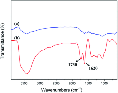
Fig. 2 shows an FTIR spectral comparison of CF and CF after acidification treatment. The two characteristic absorptions at 1730 and 1620 cm−1 for Fig. 2b correspond to C![[double bond, length as m-dash]](https://www.rsc.org/images/entities/char_e001.gif) O and C
O and C![[double bond, length as m-dash]](https://www.rsc.org/images/entities/char_e001.gif) C stretching vibrations in the carboxyl and skeleton, respectively. The appearance of the characteristic absorptions at 1730 cm−1 can prove that carboxy group appears on the surface of CF via acidification treatment. It was beneficial to improve the wettability between CF and catalyst.
C stretching vibrations in the carboxyl and skeleton, respectively. The appearance of the characteristic absorptions at 1730 cm−1 can prove that carboxy group appears on the surface of CF via acidification treatment. It was beneficial to improve the wettability between CF and catalyst.
3.2. Characterization of CNT–CF
Fig. 3 shows the SEM micrographs of CF and its treated samples by CVD with different treatment time. As shows in Fig. 3a, the surface of CF was very smooth and no obvious defect was observed. It can be known that the diameter of the carbon fiber is in the range of 6–8 μm by using the scale showed in the SEM micrographs. When the growth time was 10 min, the surface of CFs seemed to be covered by a layer of fluff, which can be inferred that a new substance grown on the surface of CFs (Fig. 3b). When the growth time increased to 20 min, the surface of CFs was more roughness, and the gap between different CF was smaller (Fig. 3c). When the growth time reached 40 min, the surface of CFs was all covered and the gap was filled by new substances (Fig. 3d). It also can be seen that the new substances were grown perpendicularly to the fiber axis and formed a radially-aligned orientation.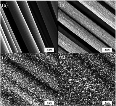 | ||
| Fig. 3 SEM micrographs of CF and as-grown CVD new substances (NSs) on the CFs with (b) 10 min, (c) 20 min, (d) 40 min processing time. | ||
Although, we hope that the new substance grown on the surface of CFs was CNTs, it is well known that carbon nanofiber (CNF), amorphous carbon may also form during the CVD process. Therefore, it is vital to testified that the new substances formed on the surface of the CFs are CNTs rather than other carbon structures. TEM, TGA and Raman spectroscopy are the most common methods used for identifying the structures of carbon.
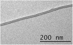
Fig. 4 shows the TEM images of MWCNTs. The TEM images revealed that the nanotubes are multiwalled and the morphology of the MWCNTs consists of a layer-by-layer graphitic structure with close distances between the interspaces of walls.
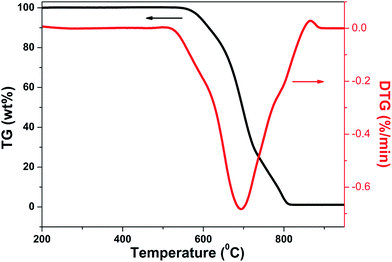
Fig. 5 shows the TG and DTG curves for NS (new substance)/CF hybrids with growth time of 20 min at oxygen-enriched atmosphere. It can be seen clearly that the TG curve started to decrease sharply in the temperature range of 550 °C to 800 °C, corresponding, the DTG curve appeared a big endothermic peak in this temperature range. This phenomenon indicated that reaction happened between NS/CF hybrids and oxygen in the temperature range of 550 °C to 800 °C. It has been testified that different carbon structures have different oxidation behaviors when they react with oxygen.39,40 In general, well-graphitized structures like CNF and CNTs have higher oxidization temperature, which is in the range of 600–700 °C. However, the oxidization temperature of amorphous carbon is just around 350 °C. The reason is amorphous carbon has much more actives sites than other two types carbon structures which is easier to react with oxygen at a relative low temperature. Consequently, combining with the TG/DTG results, it is certain that amorphous carbon is not the new substance grown on the surface CF.
Raman spectroscopy has been proven to be extremely sensitive to short-, medium-, and long-range order in solid carbon and has become a standard technique in characterizing carbon materials. Fig. 6 shows the Raman spectra of carbon fibers before and after growing CNT with different CVD processing time. The D and G peaks are characteristics of the disordered carbon and graphite in the form of CNTs and CNFs, which normally occur at 1350 cm−1 and 1580 cm−1 respectively. The relative intensity values (ID/IG) could be used to determine the degree of order of carbon material. It was reported that smaller ratio of ID/IG corresponding to the higher order degree of substances, such as CNTs, and the ID/IG ratio for CNTs is <1 while it is >1 for CNFs.41 The ID/IG ratio can also be employed for the purity assessment of CNTs that are present in a given sample.42
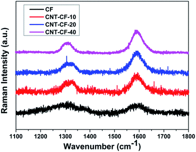 | ||
| Fig. 6 Raman spectra of carbon fibers before and after growing CNT with different CVD processing time. | ||
As shown in Fig. 6, the Raman spectrum of CF, displaying relatively weak bands at 1335 cm−1 (D band) and 1590 cm−1 (G band), which corresponded to the disordered and graphitized carbon. The Raman spectra shows that the D band intensity is much higher in case of CNTs grown carbon fibers than only CF. The ID/IG ratio of CF is 1.31, indicating it has a lower graphitic degree of order before growing new substance. The band width narrowed down and the ID/IG ratio obviously decreased with the growth time after carbon fibers grafting with new substance, which suggested the formation of ordered graphitic structures. The ID/IG ratio values of CNT/CF-10, CNT/CF-20 and CNT/CF-40 is 0.6, 0.5 and 0.43, respectively, which proves the new substances grown on the surface of CF was CNTs. It also can be seen that the ID/IG ratio decreased with the growth time increasing, which is consistent with the result reported by Kim et al.43 It was attributed to the carbon sources provided during the CVD process healed the damages probably by bridging the damaged edges of the graphite layers. Thus, TGA and Raman spectroscopy results confirmed that the new substances grown on the surface of CFs was CNTs.
3.3. Characterization of CNT–CF/PI composites
The flexural strength and flexural modulus of CF/PI and CNT–CF/PI were tested to investigate their reinforcement effect. Fig. 7 shows the variation of flexural strength and flexural modulus of the CF/PI and CNT–CF/PI with different growth time. As observed in the figure, the flexural strength of CNT–CF/PI with growth time of 10 min is slightly lower than that of CF/PI, then ascends with the growth time increasing. The flexural strength decreased first is maybe because the follow two reasons. Firstly, catalyst particles may react with CF during the CVD process under a higher temperature (740 °C) than the iron–carbon alloy formation temperature (700 °C). These reactions may damage the surface of CF then reduce the strength of CNT–CF/PI. Although harmful for the strength of CF, these reactions bring a strong anchoring effect between CNT and CF, maximizing stress transfer within the composite constituents and minimizing the chance of damage during handling. Therefore, the flexural strength of CNT–CF-10/PI was similar to that of the CF/PI. Afterwards, the flexural strength increased to 512 MPa and 560 MPa, at the growth time of 20 min and 40 min, respectively. Since the volume fraction and length of CNTs increased with the growth time increasing, the improvement effect in the strength values of the composite will offset even surpass the negative loss effect in strength. The flexural strength improvement of the CNT–CF/PI composites can be attributed to the following reasons. Firstly, the CNTs on the surface of CF, at the CNT–CF/PI interface, could enhance the bonding between the matrix and the fiber by providing mechanical interlocking. Furthermore, CNTs directly grown on the surface of CF would alleviate the agglomeration problem where CNTs uniformly dispersed in the CNT–polymer composites. The well dispersed CNTs can greatly improve the mechanical properties of the resins. The flexural modulus of the composites increased approximately 42% in the similar way because the CNTs possess higher stiffness values than CF.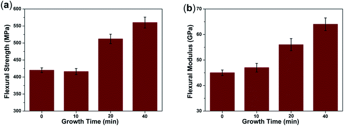 | ||
| Fig. 7 (a) Flexural strength and (b) flexural modulus of CF/PI and CNT–CF/PI composites with different growth time. | ||
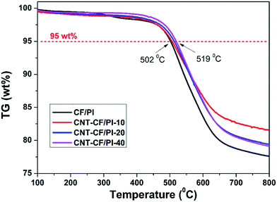
Thermal stability is another critical factor for high-tech field application of the CF/PI composites. Fig. 8 shows the TGA curves of CF/PI and CNT–CF/PI composites. The 5% weight loss temperatures of CNT/PI and CNT–CF/PI composites varied from 502 to 519 °C with the growth time varying from 0 to 40 min. Thereby, the CNTs that directly grown on the surface of CF slightly improved the thermal stability of CF/PI composites. As Shen44 suggested, regarding that the thermal degradation of a polymer begins with a chain cleavage and radical formation, the carbon surface of CNTs might act as a radical scavenger to delay the thermal degradation temperature and then improve the thermal stability of PI. Also, the thermal stability of CNT–CF/PI composites can be improved by both the excellent thermal stability of CNTs and their interactions with the polymer matrix.
DMA is also a powerful tool to investigate the thermo-mechanical properties of polymers. The storage modulus of a polymer decreases rapidly, whereas the loss modulus and loss factor (tan![[thin space (1/6-em)]](https://www.rsc.org/images/entities/char_2009.gif) δ) climb up to the maximum value, when the polymer is heated through the glass transition region. The maximum value of the tan
δ) climb up to the maximum value, when the polymer is heated through the glass transition region. The maximum value of the tan![[thin space (1/6-em)]](https://www.rsc.org/images/entities/char_2009.gif) δ is commonly regarded as the glass transition temperature (Tg). The tan
δ is commonly regarded as the glass transition temperature (Tg). The tan![[thin space (1/6-em)]](https://www.rsc.org/images/entities/char_2009.gif) δ corresponds to the energy dissipation caused by the polymer chains. For the CNT–CF/PI composites, the segment restriction increases with the increase of CNTs volume fraction or length because the CNTs restricted the movements of molecular chains nearby. As a result, segmental motion and relaxation can only occur at higher temperatures, thus the thermo-mechanical properties were improved. As observed in Fig. 9a, the Tg values of the synthesized composites changed from 218 to 245 °C. Therefore, the CNT–CF/PI composites have higher Tg values than the CF/PI, indicating that the Tg of the composites is enhanced by the incorporation of CNTs due to the confinement effect at the interface. It was also suggested that it has good interactions between the CNTs and the PI chains. As shown in Fig. 9b, the CNT–CF/PI-20 and CNT–CF/PI-40 have a distinct peak at 238 °C and 245 °C, respectively, while the other two composites do not. This phenomenon could be explained as follows: the Tg and Tf (viscous flow temperature) of CF/PI composites are adjacent, so the composites directly turn into viscous flow state when the temperature exceeds the glass transition temperature and there is no distinct peak can be observed. Since the CNTs restrict the molecular chains' mobility of the matrix resin, the matrix gets into the viscous flow state at higher temperature. Consequently, with a single for the CNT–CF/PI-20 and CNT–CF/PI-40, their Tg and Tf are separated. However, for CNT–CF/PI-10 composites, the volume fraction or length of CNTs was not enough to restraint the matrix to get into viscous flow state, hence, no distinct can be observed.
δ corresponds to the energy dissipation caused by the polymer chains. For the CNT–CF/PI composites, the segment restriction increases with the increase of CNTs volume fraction or length because the CNTs restricted the movements of molecular chains nearby. As a result, segmental motion and relaxation can only occur at higher temperatures, thus the thermo-mechanical properties were improved. As observed in Fig. 9a, the Tg values of the synthesized composites changed from 218 to 245 °C. Therefore, the CNT–CF/PI composites have higher Tg values than the CF/PI, indicating that the Tg of the composites is enhanced by the incorporation of CNTs due to the confinement effect at the interface. It was also suggested that it has good interactions between the CNTs and the PI chains. As shown in Fig. 9b, the CNT–CF/PI-20 and CNT–CF/PI-40 have a distinct peak at 238 °C and 245 °C, respectively, while the other two composites do not. This phenomenon could be explained as follows: the Tg and Tf (viscous flow temperature) of CF/PI composites are adjacent, so the composites directly turn into viscous flow state when the temperature exceeds the glass transition temperature and there is no distinct peak can be observed. Since the CNTs restrict the molecular chains' mobility of the matrix resin, the matrix gets into the viscous flow state at higher temperature. Consequently, with a single for the CNT–CF/PI-20 and CNT–CF/PI-40, their Tg and Tf are separated. However, for CNT–CF/PI-10 composites, the volume fraction or length of CNTs was not enough to restraint the matrix to get into viscous flow state, hence, no distinct can be observed.
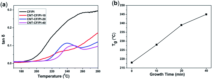 | ||
Fig. 9 (a) Tan![[thin space (1/6-em)]](https://www.rsc.org/images/entities/char_2009.gif) δ vs. temperature curves of CF/PI and CNT–CF/PI composites and (b) relationship of Tg with growth time of CNTs. δ vs. temperature curves of CF/PI and CNT–CF/PI composites and (b) relationship of Tg with growth time of CNTs. | ||
As presented in Fig. 10a, the variation in the storage modulus of CF/PI and CNT–CF/PI composites, at lower temperatures, was similar with the bending test. However, at higher temperatures, apparent difference started to appear among different curves. The onset temperature of the E′ curve marks that the CNT–CF/PI composites begin to enter the glass transition phase, where the polymer molecular segments start to move from the frozen state. By increasing the growth time, i.e. by increasing the volume fraction and length of CNTs, both the storage modulus and onset temperatures increased. When the temperature is over 260 °C beyond Tf, the storage modulus of CNT–CF/PI composites still retain a high value, of approximately 25 GPa, while that of CF/PI composites is only about 5 GPa. Therefore, the CNTs can help to improve the thermal mechanical properties of the CF/PI composites, especially in the high temperature area. More specifically, as shown in Fig. 10b, the storage modulus of the CNT–CF/PI-40 is 102 GPa at 230 °C, which is six times higher than the CF/PI composite. As discussed above, there is a good interface between CNTs and the PI resin so that the CNTs can restrain the molecular motion of the resins. Therefore, the melt viscosity of the matrix would significantly increase with increasing CNT volume fraction, illustrating the higher storage modulus of the CNT–CF/PI composites on viscous flow state. In general, the addition of CNTs significantly improved the thermal mechanical properties of CF/PI composites. With the growth time increasing, both Tg and storage modulus of the samples were enhanced.
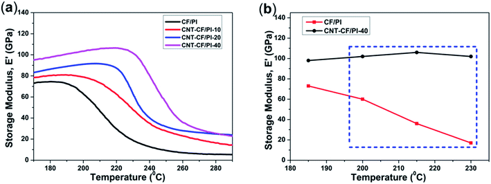 | ||
| Fig. 10 (a) Storage modulus (E′) of CF/PI and CNT–CF/PI composites and (b) storage modulus of CF/PI and CNT–CF/PI-40 composites as a function of temperature. | ||
The excellent electrical properties of CNTs also has aroused great concern about the effect of CNTs on the conductivity of the hybrid composite. It has demonstrated that the CNTs provide conducting paths throughout the composite structures. As Garcia23 reported, both the in-plane and through-thickness electrical conductivities of CNT-grafted alumina fiber fabric/epoxy composites showed 106 (in-plane) and 108 (through-thickness) improvement, which can be attributed to the CNT orientation in the through-thickness direction as well as CNT bridging of the insulating epoxy interlaminar region. Therefore, the electrical conductivity of CF/PI and CNT–CF/PI composites was measured to test the effect of CNTs on the synthesized composites in this paper. As shown in Fig. 11, the in-plane conductivity was observed and expected to be higher than the through-thickness value, which can be attributed to the high conductivity and continuous property of the CF. The in-plane conductivity ascends steadily with the growth time of CNTs. This behavior was different from the CNT–GF (glass fiber) reinforced composites.45 Because the in-plane conductivity of bidirectional composites is determined by fiber and CF who have high conductivity, the CF could cover the effect of the CNTs. Whereas, the through-thickness conductivity of CNT–CF/PI composites exhibited a sharp improvement by five orders of magnitude. The results were consistent with the study reported by Bekyarova.34 Because the CNTs can infiltrate the resin-rich regions among the layers of laminated composites, it enables the formation of continuous conductive paths in through-thickness direction. As commercial aircraft has been designed with increasing fractions of composite materials in the fuselage, such effects might be very valuable for the protection of aircraft from lightning strikes.
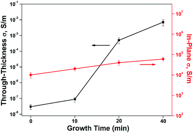 | ||
| Fig. 11 Through-thickness and in-plane electrical conductivity of CF/PI and CNT–CF/PI composites with different growth time. | ||
In order to further understand the interface properties and reinforcement mechanisms of CNT–CF/PI composites, we examined the fracture surfaces of CNT–CF/PI composites after flexural testing by SEM. SEM micrographs of the fracture surfaces are presented in Fig. 12. The fracture surface of CF/PI appeared relatively smooth and clean with fiber-pull-out tunnel left on the interface (Fig. 12a and a′). The fiber completely detached from the matrix due to a weak interfacial adhesion, corresponding with the low flexible strength of CF/PI composites. The fracture occurs at the fiber/resin interface, indicating that the fiber/matrix debonding is the dominant mechanism of flexural failure, and the weakest part of such composites is the interface. The CNTs reinforced CF/PI composites had significantly different interfacial microstructure shown in Fig. 12b–d. From Fig. 12b and b′, the fracture surface of CNT–CF/PI-10 laminate was rougher than CF/PI and the surface of the carbon fiber was coated by the matrix resin. Only few bare CF was observed, suggesting that good interface adhesion between the resin and CF was established. The good adhesion can be explained by two reasons: (1) the CNTs were closely attached on the surface of CF because of the reaction between the catalyst particles and CF, and (2) the good compatibility between the CNT and the PI chains. Furthermore, as observed in Fig. 12c, c′, d and d′, with the growth time increasing, the matrix resin was obviously damaged under flexural force showed the strong interfacial bonding between CNT–CF and PI but not fiber debonding. The CNT plays an important role in the stress transfer at the composite interface and help to improves the interface adhesion of the composites. Combined with the chemical reaction between the catalyst particles and CF, the interfacial properties as well as the mechanical properties were significantly enhanced.
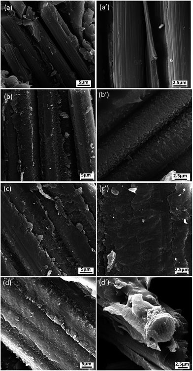 | ||
| Fig. 12 SEM micrographs of the flexural fractured surfaces for (a, a′) CF/PI composites and CNT–CF/PI composites according to the CVD process time: (b, b′) 10 min, (c, c′) 20 min, (d, d′) 40 min. | ||
3.4. Enhancement mechanism of CNT–CF/PI composites
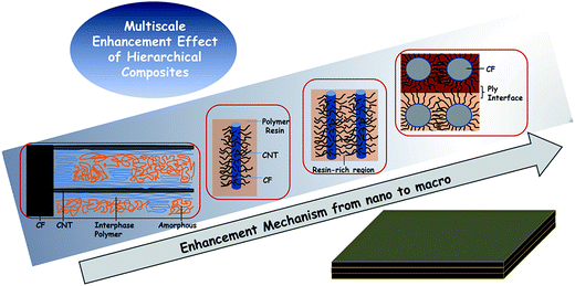
As a summary, a schematic diagram (Fig. 13) explained the reinforcing mechanism of CNT–CF/PI composites. Briefly, the CNT–CF/PI composites were enhanced by a multiscale enhancement effect. Various failure mechanisms may occur in carbon fabric composites, for the various length scales, ranging from fiber/matrix interfacial debonding, transverse micro-cracking in the polymer matrix, delamination at the ply interfaces and fiber fracture. More specifically, there are several different scales of enhancement in the CNT–CF/PI composites.At the CNT level, a nanoscale of ∼10−7 to 10−8 m, surface modification of CNT–CF by mixed acid plays an important role in enhancing the interfacial interactions between the CNTs and PI resin. CNTs can restrict the molecular motion of PI so that the Tg and Tf values were improved. The CNTs also contributed to increase the thermal stability by eliminating the free radicals. The interaction between CNT and PI leads to microstructural development of PI nearby the CNTs. And the highly ordered interphase polymer is expected to have higher mechanical properties than the neat resin.46 It is also expected to strengthen the stress transfer at the interface of CNT and the polymer, thus improving the comprehensive properties.
At the single fiber level, a microscale of ∼10−6 to 10−5 m, the interaction of the nanoscale reinforcement is on the level of the fiber/matrix interface. When grafting CNTs onto carbon fibers, a strong anchoring interaction is achieved. Thus, a good interface was established between CF and PI resins, which is of great significance. The fiber/matrix interfacial debonding is the primary damage mechanism in carbon fiber composites. However, with CNTs growing on the surface of the carbon fiber, the total fiber/matrix interfacial area reduced and that the CNT/matrix interfacial area created. So, as Hung47 studied, there are two types of interfaces: the CNT/matrix and the fiber/matrix. When applying a load on the composites, three possible fracture modes would appear, termed as Type 1, 2 and 3. In Type 1 fracture, the CNT is fractured at the CNT/fiber joint. In Type 2, the CNTs are debonded from the surrounding matrix and pulled out with the fiber. Type 3 refers to the case where the CNTs are fragmented. All modes may result to consuming additional energy and hence significantly contribute to the enhanced fracture toughness properties, because of energy-dissipating mechanisms. It is necessary to mention that the Type 1 fracture is the prevailing type. But it still needs a higher energy level to debond from the CNT/fiber interface, compared to that of the fiber/matrix interface in CF/PI composites. Thus, the flexural strength and modulus is attributed to a stiffer CNT-reinforced matrix, which helped to improve fiber–matrix interfacial adhesion and strong synergetic effect between the nano and micro-scale fillers.
At the bundle and interlamination level, a microscale of ∼10−4 to 10−3 m, the CNTs can penetrate into the narrow matrix-rich regions among individual fibers. Electrically or thermally conductive pathways can be created between or around the fiber reinforcements and it explains the enhanced electrical conductivity. Moreover, the CNTs in the matrix-rich regions, within the layers of laminated composites, could improve interlaminar or through-thickness reinforcement and other matrix-dominated properties.
Through the comparison between fiber composites with dispersed CNTs and fiber composites with locally-deposited CNTs (Table 1), we can further illustrate the multiscale enhancement effect of CNT–CF. The ILSS and thermal stability of CNT–CF/PI are clearly superior to those fiber composites with dispersed CNTs.45,48 This illustrates that CF and CNTs which directly growing on the surface of fiber have synergistic effect. Compared to CNT–CF/PI, the through-thickness electrical conductivity of GF/vinyl ester/SWCNTs49 is slightly less. This can be explained that CNTs are dispersed throughout the matrix and infused through the fiber bundles, electrically percolating pathways can be formed throughout the fiber composite.
| Fiber | Matrix | Nanofiller | ILSSa | Thermal stabilitya | Through-thickness electrical conductivityb |
|---|---|---|---|---|---|
| a ILSS: interlaminar shear strength. Increased value.b ILSS: interlaminar shear strength. Increased magnification. | |||||
| CF48 | Epoxy | SWCNTs | 1.8% | — | — |
| GF45 | PEEK | SWCNTs | — | 12 °C | — |
| GF49 | Vinyl ester | SWCNTs | — | — | 103 |
| CF | PI | CNT–CF | 62% | 19 °C | 104 |
4. Conclusions
In summary, we developed an effective approach to fabricate polyimide based hierarchical composite reinforced with carbon nanotubes directly grown on surface of carbon fabric. TGA, SEM and Raman spectrum studies testified that CNTs grown on the surface of carbon fabric by CVD successfully. The measured properties of the hybrid composites were found to improve with the increasing amount of deposited carbon nanotubes. The results showed enhanced thermal stability, electrical conductivity, and mechanical properties as compared to the composited prepared by conventional carbon fabric reinforced polyimide. The significant improvement of the hierarchical composites can be explained by different scale enhancement mechanisms from nanoscale to macroscale. At the CNT level, the CNTs can restrict the segmental motion of PI molecules and reinforce the resin matrix. At the single fiber level, a strong anchoring interaction can be established between CF and PI resin after grafting CNTs onto carbon fibers, which can greatly improve stress transfer and other interfacial properties. At the bundle and interlamination level, the CNTs can penetrate into the narrow matrix-rich regions among individual fibers and between the layers of laminated composites, thus electrically or thermally conductive pathways can be created.Conflict of interest
The authors declare no competing financial interest.Acknowledgements
We acknowledge financial support from National Basic Research Program of China (Grant 2011CB605704).References
- P. Mouritz, E. Gellert, P. Burchill and K. Challis, Composite Structures, 2001, 53, 21 CrossRef.
- T. Carlson, D. Ordeus, M. Wysocki and L. E. Asp, Compos. Sci. Technol., 2010, 70, 1135 CrossRef CAS.
- J. Qiu, C. Zhang, B. Wang and R. Liang, Nanotechnology, 2007, 18, 275708 CrossRef.
- R. F. Elhajjar and S. S. Shams, Polym. Test., 2014, 35, 45 CrossRef CAS.
- N. Yamamoto, R. G. de Villoria and B. L. Wardle, Compos. Sci. Technol., 2012, 72, 2009 CrossRef CAS.
- S. He, C. Lu and S. Zhang, ACS Appl. Mater. Interfaces, 2011, 3, 4744 CAS.
- X. Qu, M. Ji, L. Fan and S. Yang, High Perform. Polym., 2011, 23, 281 CrossRef CAS.
- J. Li and T. Bai, Polym.-Plast. Technol. Eng., 2011, 50, 1393 CrossRef CAS.
- M. Hojo, T. Ando, M. Tanaka, T. Adachi, S. Ochiai and Y. Endo, Int. J. Fatigue, 2006, 28, 1154 CrossRef CAS.
- A. P. Mouritz, K. H. Leong and I. Herszberg, Composites, Part A, 1997, 28, 979 CrossRef.
- M. Sadighi, R. C. Alderliesten and R. Benedictus, Int. J. Impact Eng., 2012, 49, 77 CrossRef.
- X. Chen, M. Farber, Y. Gao, I. Kulaots, E. M. Suuberg and R. H. Hurt, Carbon, 2003, 41(8), 1489–1500 CrossRef CAS.
- G. M. Wu, Mater. Chem. Phys., 2004, 85(1), 81–87 CrossRef CAS.
- A. Benatar and T. G. Gutowski, Polym. Compos., 1986, 7(2), 84–90 CrossRef CAS.
- A. Y. Boroujeni, M. Tehrani, A. J. Nelson and M. Al-Haik, Polym. Compos., 2016, 37, 2639–2648 CrossRef CAS.
- G. N. De, L. M. Zhang, A. Magrez, L. Forro, J. P. Locquet, I. Verpoest and J. W. Seo, Diamond Relat. Mater., 2015, 51, 39–48 CrossRef.
- S. C. Chen, Y. Y. Feng, M. M. Qin, T. X. Ji and W. Feng, Carbon, 2017, 116, 84–93 CrossRef CAS.
- J. G. Zhang and G. Du, J. Thermoplast. Compos. Mater., 2017, 28, 1250–1259 Search PubMed.
- Y. Wang, L. Meng, L. Fan, G. Wu, L. Ma and Y. Huang, RSC Adv., 2015, 5, 44492 RSC.
- A. S. Babal, B. P. Singh, J. Jyoti, S. Sharma, A. K. Arya and S. R. Dhakate, RSC Adv., 2016, 6, 67954 RSC.
- P. Lv, Y. Feng, P. Zhang, H. Chen, N. Zhao and W. Feng, Carbon, 2011, 49, 4665 CrossRef CAS.
- T. R. Pozegic, I. Hamerton, J. V. Anguita, W. Tang, P. Ballocchi, P. Jenkins and S. R. P. Silva, Carbon, 2014, 74, 319 CrossRef CAS.
- E. J. Garcia, B. L. Wardle, A. J. Hart and N. Yamamoto, Compos. Sci. Technol., 2008, 68, 2034 CrossRef CAS.
- V. P. Veedu, A. Y. Cao, X. S. Li, K. G. Ma, C. Soldano, S. Kar, P. M. Ajayan and M. N. Ghasemi-Nejhad, Nat. Mater., 2006, 5, 457 CrossRef CAS PubMed.
- C. Wang, Y. Li, L. Tong, Q. Song, K. Li, J. Li, Q. Peng, X. He, R. Wang, W. Jiao and S. Du, Carbon, 2014, 69, 239 CrossRef CAS.
- H. Qian, A. Bismarck, E. S. Greenhalgh, G. Kalinka and M. S. P. Shaffer, Chem. Mater., 2008, 20, 1862 CrossRef CAS.
- N. Chakrapani, B. Q. Wei, A. Carrillo, P. M. Ajayan, R. S. Kane and P. Natl, Proc. Natl. Acad. Sci. U. S. A., 2004, 101, 4009 CrossRef CAS PubMed.
- H. Qian, A. Bismarck, E. S. Greenhalgh and M. S. P. Shaffer, Compos. Sci. Technol., 2010, 70, 393 CrossRef CAS.
- F. Zhang, R. Wang, X. He, C. Wang and L. Ren, J. Mater. Sci., 2009, 44, 3574 CrossRef CAS.
- H. Qian, A. Bismarck, E. S. Greenhalgh and M. S. P. Shaffer, Compos. Sci. Technol., 2010, 70, 393 CrossRef CAS.
- R. J. Sager, P. J. Klein, D. C. Lagoudas, Q. Zhang, J. Liu, L. Dai and J. W. Baur, Compos. Sci. Technol., 2009, 69, 898 CrossRef CAS.
- E. T. Thostenson, W. Z. Li, D. Z. Wang, Z. F. Ren and T. W. Chou, J. Appl. Phys., 2002, 91, 6034 CrossRef CAS.
- M. F. L. De Volder, S. H. Tawfick, R. H. Baughman and A. J. Hart, Science, 2013, 339, 535 CrossRef CAS PubMed.
- E. Bekyarova, E. T. Thostenson, A. Yu, H. Kim, J. Gao, J. Tang, H. T. Hahn, T. W. Chou, M. E. Itkis and R. C. Haddon, Langmuir, 2007, 23, 3970 CrossRef CAS PubMed.
- E. T. Thostenson Jr, J. J. Gangloff, C. Li and J. Byun, Appl. Phys. Lett., 2009, 95, 1227 CrossRef.
- H. Qian, E. S. Greenhalgh, M. S. P. Shaffer and A. Bismarck, J. Mater. Chem., 2010, 20, 4751 RSC.
- A. M. Diez-Pascual, M. Naffakh, C. Marco, M. A. Gomez-Fatou and G. J. Ellis, Curr. Opin. Solid State Mater. Sci., 2014, 18, 62 CrossRef CAS.
- T. Huang, Y. Xin, T. Li, S. Nutt, C. Su, H. Chen, P. Liu and Z. Lai, ACS Appl. Mater. Interfaces, 2013, 5, 4878 CAS.
- R. B. Mathur, S. Seth, C. Lal, R. Rao, B. P. Singh, T. L. Dhami and A. M. Rao, Carbon, 2007, 45, 132 CrossRef CAS.
- R. B. Mathur, S. Chatterjee and B. P. Singh, Compos. Sci. Technol., 2008, 68, 1608 CrossRef CAS.
- S. P. Sharma and S. C. Lakkad, Composites, Part A, 2011, 42, 8 CrossRef.
- R. A. DiLeo, B. J. Landi and R. P. Raffaelle, J. Appl. Phys., 2007, 101, 4307 CrossRef.
- K. J. Kim, W. Yu, J. H. Youk and J. Lee, ACS Appl. Mater. Interfaces, 2012, 4, 2250 CAS.
- Z. Shen, S. Bateman, D. Y. Wu, P. McMahon, M. Dell'Olio and J. Gotama, Compos. Sci. Technol., 2009, 69, 239 CrossRef CAS.
- A. M. Diez-Pascual, B. Ashrafi, M. Naffakh, J. M. Gonzalez-Dominguez, A. Johnston, B. Simard, M. T. Martinez and M. A. Gomez-Fatou, Carbon, 2011, 49, 2817 CrossRef CAS.
- M. L. Minus, H. G. Chae and S. Kumar, Macromol. Rapid Commun., 2010, 31, 310 CrossRef CAS PubMed.
- K. H. Hung, W. S. Kuo, T. H. Ko, S. S. Tzeng and C. F. Yan, Composites, Part A, 2009, 40, 1299 CrossRef.
- P. R. Thakre, D. C. Lagoudas, J. Zhu, E. V. Barrera and T. S. Gates, in 47th AIAA structure, structural dynamics and materials conference proceedings, Newport, RI, May 1–4 2006, AIAA 2006–1857 Search PubMed.
- E. T. Thostenson, J. J. Gangloff, C. Li and J. Byun, Appl. Phys. Lett., 2009, 95, 73–111 CrossRef.
| This journal is © The Royal Society of Chemistry 2017 |

