 Open Access Article
Creative Commons Attribution 3.0 Unported Licence
Distinctly enhanced permeability and excellent microwave absorption of expanded graphite/Fe3O4 nanoring composites†
Yanting Zhao,
Lin Liu,
Kedan Jiang,
Mengting Fan,
Chen Jin,
Jianv Han,
Wenhua Wu and
Guoxiu Tong *
*
College of Chemistry and Life Sciences, Zhejiang Normal University, Jinhua 321004, People's Republic of China. E-mail: tonggx@zjnu.cn; Fax: +86-579-82282269; Tel: +86-579-82282269
First published on 15th February 2017
Abstract
To break Snoek's limit and obtain high permeability, expanded graphite/Fe3O4 nanoring composites have been synthesized via a solvothermal-surface modification-sintering approach. A series of characterizations have confirmed the formation of the composites. Studies of the influence of compound mode, Fe3O4 shape, and filling mass fraction on the EM parameters reveal that the recombination of Fe3O4 NRs and EG can distinctly enhance permeability and permittivity. The ε′ and ε′′ values of the composites are 1.5–70.0 and 4.0–858.0 times as many as EG′ and 22.2–26.0 and 214.0–611.0 times as many as Fe3O4 NRs', respectively. Their μ′ and μ′′ values are around 2.8–3.0 and 2.2–100 times the Fe3O4 NRs', respectively. This significant enhancement is caused by the synergistic effect of the planar anisotropy, plasmon resonance, electromagnetic coupling, and interfacial polarization. The EG/Fe3O4 NR composites with a mass fraction of 10 wt% achieved the maximum RL value of −24.8 dB at 6.8 GHz and the corresponding frequency range (RL ≤ −20 dB, 99% absorption) is 8.0 GHz. Our findings confirm that the above composites are not only excellent microwave absorbers of broad bandwidth but are also light weight and can break Snoek's limit.
1. Introduction
The design and preparation of high-efficient microwave-absorbing materials are crucial ways to solve the serious electromagnetic (EM) interference problems. The complex permittivity (εr = ε′ − jε′′), complex permeability (μr = μ′ − jμ′′), and the matching of the absorbers determine their absorption properties.1,2 Soft magnetic materials, a kind of important microwave absorber, are widely used in microwave devices. These magnetic materials generally follow Snoek's law:3,4 , where γ is the gyromagnetic ratio and Ms is the saturation magnetization. Obviously, Ms suppresses the enhancement of Snoek's limit. Thus, it is still a huge challenge to obtain a magnetic material with high permeability as well as high resonant frequency simultaneously.
To break the Snoek's limit and obtain high permeability, the following measures were usually taken: first, effective magnetization (Ms) is enhanced via changing the content of the magnetic part in materials1,2,5 or optically induced magnetization.6 Second, eddy current effects are restricted by controlling the thickness smaller than their skin depth or by surface-modifying the magnetic particles with materials with low permittivity,7 resulting in higher complex permeability in a higher frequency range. Third, the magnitude of the anisotropic field8,9 is adjusted or an extra geometrical field upon scattering of spin waves is introduced.10 The flake-shaped magnetic materials (i.e., Fe,11 FeCuNbSiB, Fe3Co2,12–15 etc.) are found to exceed Snoek's limit and exhibit enhanced permeability because of the existence of two types of magnetic anisotropy (out-of-plane anisotropy and easy-magnetization-plane anisotropy).16 Compared with the former two ways, changing anisotropic field can adjust permeability in a large scale. However, the large anisotropic field necessarily increases the difficulty to the material synthesis.
Recently, we found that Fe3O4 nanorings (NRs) exhibited the significantly enhanced permittivity at 2–18 GHz owing to plasmonic resonance behavior.5,17,18 To further enhance the permeability, we have investigated the EM parameters and microwave-absorbing properties of expanded graphite (EG)/Fe3O4 NR composites.
2. Experimental section
2.1 Preparation
![[thin space (1/6-em)]](https://www.rsc.org/images/entities/char_2009.gif) 000) were added into water (150 mL), then the mixture was vigorously stirred at room temperature for 12 h. The surface-modified expanded graphite was collected by filtration and washed with water several times.
000) were added into water (150 mL), then the mixture was vigorously stirred at room temperature for 12 h. The surface-modified expanded graphite was collected by filtration and washed with water several times.2.2 Characterization
The morphology, structure, composition, and phase of the as-prepared samples were studied by Field-emission scanning electron microscope (FE-SEM, Hitachi S-4800, 10 kV), transmission electron microscope (TEM, JEM-2100F, 200 kV), the corresponding selected-area electron diffraction (SAED) pattern, and energy dispersive X-ray spectrometry (EDX, EX-250, Horiba, Japan), X-ray diffraction (XRD, D/MAX-IIIA, CuKα radiation, λ = 0.15406 nm, 10° min−1), and Fourier transform infrared (FTIR, Nicolet FTIR-170SX, 4000–400 cm−1, room temperature) absorption spectra, respectively.2.3 Property measurement
The EM parameters were measured in the 2–18 GHz range through the transmission/reflection method with an Agilent 5230A network analyzer. The measured samples were prepared by uniformly mixing the absorbents with paraffin matrix in a mass fraction of 10–30% and compacted into ring shape of 7.00 mm outer diameter and 3.04 mm inner diameter.3. Results and discussion
3.1 Formation mechanism
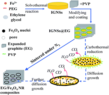
Scheme 1 schematically illustrates the formation process of EG/Fe3O4 NR composites. EG/Fe3O4 NR composites were synthesized via a three-step approach. First of all, a solvothermal reaction was used to synthesize the IGNSs with the chemical formula of FeIII3.3FeII(C2H3O3)11.9·4H2O. Owing to the similar brucite-structure, the IGNSs trend to form sheet-like crystal nuclei, which gradually assembled into elliptical nanosheets under the guidance of PEG. Afterward, the as-obtained expanded graphite (EG) was modified by PVP in aqueous solution. The IGNSs were combined with the surface-modified EG via a leaching process. Finally, EG/Fe3O4 NR composites were obtained via sintering EG/IGNSs composites at 400 °C for 2 h under N2. During sintering, the decomposition and carbonization of the IGNSs produced heat and gases (such as CO, H2O, and CO2). The detailed mechanism has been explained in ref. 19. These reactions form numerous pores in the center of nanosheets, which increased stress concentration. In order to decrease stress concentration, pore size increased by swallowing up contiguous small pores and the nanocrystals diffused from the center to the edge.5,17,18 Such changes result in the formation of EG/Fe3O4 NR composites.3.2 Results from SEM and TEM
SEM observation discloses that EG has a worm-like structure; the width and length of the worm are 26.0–63.0 and 44.8–110.0 μm, respectively (Fig. 1a). The worm-like structure is composed by a thin graphite layer with 20–70 nm thickness and 26.0–110.0 μm length (Fig. 1b). The graphite layers take on smooth surfaces (Fig. 1c) and large flakiness ratios of about 578–2444. Strong and regular diffracted spots in the SAED patter (inset in Fig. 1c) confirm that EG was the nature of single crystal. After modifying EG with Fe3O4 NRs, Fe3O4 NRs were uniformly spread on the surface of EG and between layers in the form of single layers (Fig. 1d, e and S1†). SEM images in Fig. 1e showed that Fe3O4 were the elliptical NRs with long axes of 145 ± 20 nm, a wall thickness of approximately 26 ± 5 nm, a height of 28 ± 5 nm, and a long-to-short axis ratio of 1.6–2.3. Clear diffraction rings in the SAED patter (Fig. 1g) confirm that the polycrystalline Fe3O4 NRs grow on the surface of single crystal EG. The elemental composition and distribution of EG/Fe3O4 NR composites were shown in the Fig. 1h–k. It was can be seen that three elements (Fe, C, O) was detected and the ring-like Fe3O4 grow on the surface of EG.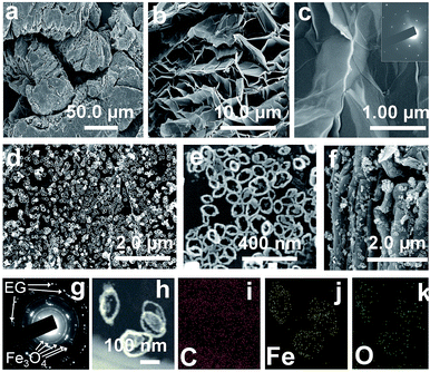 | ||
| Fig. 1 (a–f) SEM images, (g) SAED pattern, and (h–k) STEM images of (a–c) pure EG and (d–k) EG/Fe3O4 NR composites. The inset in (c) is the corresponding SAED pattern. | ||
3.3 XRD, FTIR, and EDX analysis
XRD is usually used to investigate the phase structure of the samples. In Fig. 2a, the XRD peaks denoted by ♦ and ◊ are well assigned to the cubic inverse spinel structure of Fe3O4 (magnetite) [a = 0.83905 nm; space group (227); JCPDS 65-3107] and expended graphite [JCPDS 65-6216], respectively. Energy-dispersive X-ray spectrometry analysis confirms that three elements (Fe, C, and O) are detected and the C/Fe atomic ratio is 22.58 (Fig. 2b). To investigate the growth of Fe3O4 on the EG, FTIR characterization is performed. In Fig. 2c, for pure EG, the IR absorption at 1400 cm−1 may be attributed to tertiary C–OH groups, the peak at 1656 cm−1 to the C![[double bond, length as m-dash]](https://www.rsc.org/images/entities/char_e001.gif) C skeleton vibrations of graphitic domains,20,21 the peak at 2400 cm−1 to the organic species or the remaining COO− species on graphene, and the broad absorption peak at 3400 cm−1 to O–H stretching vibration. In addition the above three peaks, EG/Fe3O4 NR composites take on a new peak at 580 cm−1, corresponding to the characteristic peak of Fe3O4.19 The results from XRD, FTIR and EDX data confirm that the samples are a composite of EG and Fe3O4.
C skeleton vibrations of graphitic domains,20,21 the peak at 2400 cm−1 to the organic species or the remaining COO− species on graphene, and the broad absorption peak at 3400 cm−1 to O–H stretching vibration. In addition the above three peaks, EG/Fe3O4 NR composites take on a new peak at 580 cm−1, corresponding to the characteristic peak of Fe3O4.19 The results from XRD, FTIR and EDX data confirm that the samples are a composite of EG and Fe3O4.
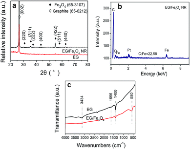 | ||
| Fig. 2 (a) XRD patterns, (b) EDX spectrum, and (c) FTIR spectra of pure EG and EG/Fe3O4 NR composites. | ||
3.4 Electromagnetic properties
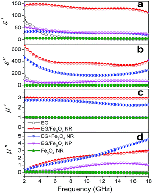
The EM parameters were measured in the 2–18 GHz range through the transmission/reflection method with an Agilent 5230A network analyzer. Fig. 3 shows the plots of EM parameters for various samples at 2–18 GHz. Pure EG is a resistance loss-type absorbent with high ε′ and ε′′ values (ε′ = 1.6–91.8 and ε′′ = 0.47–165.37). The ε′ and ε′′ values sharply decrease with frequency as the eddy current loss induced by EM waves increases with increased f. Pure Fe3O4 NRs show weak magnetic and dielectric losses with very low EM parameters at 2–18 GHz (ε′ = 4.8–6.3, ε′′ = 1.1–1.6, μ′ ≈ 1.0, and μ′′ = 0–0.12) (Fig. 3). We found that if layered EG is surface modified with Fe3O4 NRs (the samples are called EG/Fe3O4 NR composites), then the complex permittivity and permeability will noticeably be enhanced. The ε′, ε′′, μ′, and μ′′ fluctuate at ranges of 110.0–147.1, 329.1–663.3, 2.95–3.05, and 0.25–2.95, respectively (Fig. 3). The above ε′ and ε′′ values are 1.5–70.0 and 4.0–858.0 times as many as EG′ and 22.2–26.0 and 214.0–611.0 times as many as Fe3O4 NRs', respectively. The above μ′ and μ′′ values are around 2.8–3.0 and 2.2–100 times as many as the Fe3O4 NRs', respectively. These results suggest that the EG/Fe3O4 NR composites have significantly higher storage capability and have more electric and magnetic energy loss than EG and Fe3O4 NRs.The influences of compound mode, Fe3O4 shape, and filling mass fraction on the EM parameters were systematically investigated to decipher the enhancement effect of EM parameters. If EG is combined with Fe3O4 nanoparticles (NPs) (the samples are marked as EG/Fe3O4 NPs, SEM images is shown in Fig. S2†), then the ε′, ε′′, μ′, and μ′′ values of EG/Fe3O4 NPs significantly decline compared with those of EG/Fe3O4 NRs and EG + Fe3O4 NRs (Fig. 3). This finding demonstrates that the unique geometrical configuration of NRs plays a key role in the EM enhancement effect.1,2 When Fe3O4 NRs are blended with EG (the samples were marked as EG + Fe3O4 NRs), the ε′, ε′′, and μ′ values of EG + Fe3O4 NRs are significantly lower than those of EG/Fe3O4 NR composites (Fig. 3). Our data indicate that the interface between EG and Fe3O4 NRs as well as the synergistic effect of EG and Fe3O4 NRs contributes greatly to EM parameter enhancement.1,2
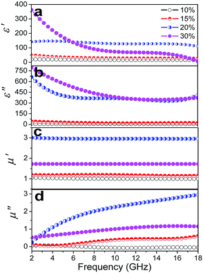
Additionally, the filling mass fraction of EG/Fe3O4 NR composites in the wax matrix had much influence on the EM parameters. The ε′, ε′′, μ′, and μ′′ values show a slight increase at 10–15% and a rapid increase at 20% (Fig. 4). If the filling mass fraction is further increased to 30%, then the ε′ and ε′′ values slightly increase in low frequencies and the ε′′ values decrease at high frequencies (Fig. 4a and b). The values of μ′ and μ′′ significantly fall (Fig. 4c and d). The rapid increase is usually related to the local formation of the conductive network,22 whereas the rapid decrease is due to the skin depth. We may reasonably conclude that the microcurrent caused by the percolation electric network favors the EM parameter enhancement. We replace EG with CNTs to further confirm the role of the planar anisotropy. No permeability enhancement is found in the CNT/Fe3O4 NR composites (Fig. S3†). The planar anisotropy of EG is also a crucial factor for the permeability enhancement.
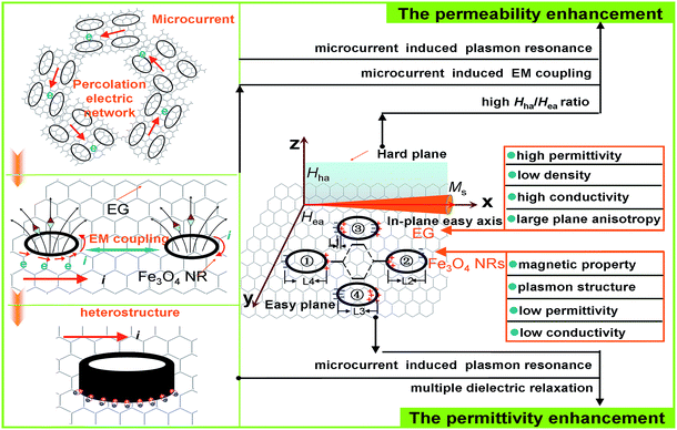
In general, the permittivity increases with the increasing defects, aspect ratio, and specific surface area (SBET) because of the enhanced space charge, orientation, or interface polarization.5,23,24 Based on the above results, the permittivity enhancement for EG/Fe3O4 NR composites reported here is mainly ascribed to the unique geometrical configuration of NRs and the heterostructure of EG and Fe3O4 NRs (Fig. 5).
(1) In the heterostructured EG/Fe3O4 NR composites, additional interfaces exist between EG and Fe3O4, resulting in the interfacial polarization.25,26 The lower work function of EG (2.0–5.0 eV) than that of Fe3O4 (ca. 5.52 eV) facilitates electron transition from EG to Fe3O4 NRs. The charges accumulating at the heterogeneous interface form numerous dipoles, thus enhancing the permittivity (Fig. 5). Cole–Cole curves verify the multiple relaxation mechanism of EG/Fe3O4 NR composites. According to the Debye dipolar relaxation,1,2 each single semicircle (generally denoted as the Cole–Cole semicircle) in the plot of ε′ versus ε′′ would correspond to one Debye relaxation process. As for EG, a Cole–Cole semicircle is found in the low filling mass fraction (5–10%), corresponding to a dielectric relaxation process (Fig. S4a and b†). A distorted line is observed in the high filling mass fraction (15%, 20%, and 30%) (Fig. 6a, S4c and d†), suggesting the existence of Maxwell–Wagner relaxation, electron polarization, and dipolar polarization. Fe3O4 NRs exhibited a Cole–Cole semicircle (Fig. 6b), indicating a dielectric relaxation process. Surface charges pile up at the interfaces between two different dielectric medias and give rise to a new Debye-like relaxation process under an external alternating voltage. As a result, EG/Fe3O4 NR composites show three semicircles at 10%, two semicircles at 20%, and a distorted line at 30% (Fig. 6c–e). These results indicate that the multiple Debye dielectric relaxations contribute greatly to permittivity enhancement at low mass fraction. Maxwell–Wagner relaxation, electron polarization, and dipolar polarization play key roles in permittivity enhancement at high mass fraction. (2) Under an alternating EM field, the ring-like structure can generate induced current and excite electrons. The excited electrons oscillate collectively as a wave, causing considerably enhanced polarization and local electric fields in the ring cavity. Fe3O4 has low conductivity σ, which mainly derives from the hopping of the minority-spin “extra” electron between Fe2+ and Fe3+ ions in the B site. EG is a resistance-loss-type absorber with high conductivity (0.07 mΩ cm) and dielectric loss. The high electrical conductivity σ comes from migrating conductance in the graphite plane direction and the hopping conductance among disordered graphite layers. A recombination of Fe3O4 NRs and EG promotes electron transition from EG to Fe3O4 NRs, which provides more excited electrons in forming the induced current inside Fe3O4 NRs. Afterward, the larger induced current generates stronger effect of plasmon resonance EM field enhancement. (3) The percolation electric network generates the microcurrent along the graphite plane direction in the alternating electric field, as illustrated in Fig. 5. When the microcurrent passes the interfaces between Fe3O4 NRs and EG, numerous dipoles form on their interfaces, thus enhancing the permittivity.
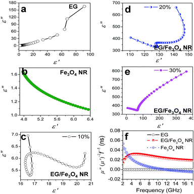 | ||
| Fig. 6 (a–e) Cole–Cole semicircles (ε′ vs. ε′′) and (f) μ′′(μ′)−2f−1 (representing eddy current loss) versus frequency of the samples. | ||
In addition to permittivity enhancement, the permeability enhancement is exhibited by EG/Fe3O4 NR composites. The permeability can be enhanced by increasing the shape anisotropy and Ms or decreasing the size smaller than their skin depth.7 In this study, EG/Fe3O4 NR composites exhibit lower Ms value but larger permeability than those of pure Fe3O4 NRs (Fig. S5†). Thus, the permeability enhancement is due to the synergistic effect of magnetic Fe3O4 NRs and layered EG with planar anisotropy. First, the planar anisotropy of layered EG is the key factor in the enhanced permeability. Pure EG layers with high planar anisotropy cannot generate the EM enhancement effect because of antiferromagnetism and very small Ms. When Fe3O4 NRs with high Ms (ca. 60.0 emu g−1) are distributed on the surface of EG layers, the EG/Fe3O4 NR composites possess not only high Ms (ca. 21.0 emu g−1) but also large planar anisotropy. According to the Landau–Lifshitz–Gilbert equation,9,27  , where Hha and Hea are the effective anisotropy fields when the magnetization deviates from the easy axis (x direction) in the hard plane (x–z) and in the easy plane (x–y), respectively (Fig. 5), the high static permeability can be achieved for ideal bianisotropy magnetic materials with large Hha/Hea ratio and/or high Ms. Thus, a recombination of layered EG and magnetic Fe3O4 NRs can noticeably enhance permeability.
Second, the contributions of Fe3O4 NRs to permeability enhancement of the EG/Fe3O4 NR composites are associated with plasmon resonance and EM coupling. The higher permeability of EG/Fe3O4 NR composites than that of EG/Fe3O4 NP composites demonstrates that the ring-shaped structure is a key factor to enhance the permeability. Magnetic NRs act as plasmonic structures, which induce plasmon resonance-enhanced permeability.1,2 When a small quantity of Fe3O4 NRs was distributed on the surface of EG, EG and the percolation electric network generate a large number of excited electrons. The excited electrons oscillate collectively inside NRs as a wave, enhancing permeability. The enhancement effect cannot be observed in EG/ZnO NR composites. The magnetic and electric properties are two indispensable factors for the EM enhancement of NRs. This is because magnetic and electric NRs act as both magnetic and electric-field-sensitive nano-antennae and emit either a confined magnetic or a confined electric field in the alternating EM field.28 This finding demonstrates that the EM coupling play critical roles in the enhancement effect (Fig. 5).
Third, the recombination of layered EG and magnetic Fe3O4 NRs can reduce the skin effect, resulting in enhanced permeability. The relationship among eddy current loss of a magnetic particle with diameter (d) less than the skin depth can be expressed by  ,29 where f is the applied frequency and σ is the conductivity of the particle. According to skin-effect criterion,1,2 if magnetic loss only results from eddy current loss effect, then the values of eddy current loss (denoted by μ′′(μ′)−2f−1 = 2πμ0σd2/3) are constant when f is changing.18 In this study, the values of eddy current loss are constant for EG. In addition, a strong natural resonance peak below 2 GHz can be found in pure Fe3O4 NRs, and broad and strong resonance peaks over 2–18 GHz are observed for EG/Fe3O4 NR composites (Fig. 6f). These results confirm that the magnetic Fe3O4 NRs with low permittivity and conductivity modified on the surface of EG can depress eddy current loss and generate strong plasmon resonances. The resonance peak of EG/Fe3O4 NR composites shift to high frequency compared with Fe3O4 NRs. This finding indicates that the composites can break Snoek's limit. Further experimental and theoretical work is needed to elucidate the mechanisms underlying these phenomena.
3.5 Microwave absorption
To evaluate the microwave absorption properties, the reflection loss (RL) at the surface of a metal-backed single layer was optimized based on the equation1,2 RL (dB) = 20![[thin space (1/6-em)]](https://www.rsc.org/images/entities/char_2009.gif) log|(Zin − Z0)/(Zin + Z0)|, where
log|(Zin − Z0)/(Zin + Z0)|, where  is the characteristic impedance of free space. Input impedance at the free space and material interface is denoted as
  , where f is the given frequency and d is the coating thickness. The RL peaks are found to gradually shift to a lower frequency with increasing sample thickness (Fig. 7a). The maximum RL value is achieved when the matching thickness (tm) and the matching frequency (fm) satisfy the equation
  (n = 1, 3, 5…), where c is the velocity of light. In the 3D RL mapping plots (Fig. 7b), two absorbing bands are observed for EG/Fe3O4 NR composites at the wavelengths of λ/4 and 3λ/4. The absorbing band of RL ≤ −20 dB focuses on the quarter wavelength of the sample. This result demonstrates that the microwave absorption for EG/Fe3O4 NR composites mainly obeys the quarter-wavelength cancellation model. The maximum RL value of −24.8 dB at 6.8 GHz was achieved at a mass fraction of 10 wt% (Fig. 7a and b). The corresponding frequency range (RL ≤ −20 dB, 99% absorption) is 8.0 GHz. For pure EG, excellent microwave absorption property was observed at 20 wt% with a maximum RL value of −48.1 dB at 6.64 GHz (Fig. 7b). RL values are below −20 dB over just 7.28–9.20 GHz (Fig. 7c). Fe3O4 NRs exhibit a maximum RL value of just −17.4 dB at 18.0 GHz with a mass fraction of 20 wt% (Fig. 7d). A comparison reveals that EG/Fe3O4 NR composites are eminently suitable for microwave absorption materials with low density and a broad bandwidth compared with pure EG and Fe3O4 NRs. The excellent microwave-absorbing properties are ascribed to the heterostructures of magnetic Fe3O4 NRs and layered EG, which enhances multiple scattering, oscillation resonance absorption, microantenna radiation, and interference loss.1,2,17,18
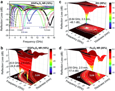 | ||
| Fig. 7 The calculated reflection losses for (a and b) EG/Fe3O4 NR composites, (c) EG, and (d) Fe3O4 NRs at various mass fractions and coating thicknesses (mm). | ||
4. Conclusions
In conclusion, the effects of distinct permeability and permittivity enhancement at 2–18 GHz are found in EG/Fe3O4 NR composites made from a solvothermal-surface modification-sintering approach. The ε′ and ε′′ values of EG/Fe3O4 NR composites are 1.5–70 and 4.0–858 times as many as EG′, respectively. The ε′, ε′′, μ′, and μ′′ values are around 22.2–26.0, 214–611, 2.8–3.0, and 2.2–100 times as many as the Fe3O4 NRs', respectively. Studies on influences of compound mode, Fe3O4 shape, and filling mass fraction on the EM parameters confirm that significant permittivity enhancement is due to the heterostructure and plasmon resonance; significant permeability enhancement is due to the easy-plane anisotropy, plasmon resonance, and EM coupling. An optimal microwave absorption property was generated in EG/Fe3O4 NR composites with a mass fraction of 10% and an absorption range (RL ≤ −20 dB) of 8 GHz. These findings develop a novel approach for the permeability and permittivity enhancement and provide new composites for microwave absorbers of broad bandwidth and light weight.Acknowledgements
This work was supported by the National Natural Scientific Foundation of China (51102215 and 51672252), Public Utility Items of Zhejiang Province (2015C31022), Natural Scientific Foundation of Zhejiang Province (LY14B010001 and Y4100022), and National Innovation and Entrepreneurship Training Program of Undergraduates (201610345010).Notes and references
- G. X. Tong, Y. Liu, T. T. Cui, Y. N. Li, Y. T. Zhao and J. G. Guan, Appl. Phys. Lett., 2016, 108, 072905 CrossRef.
- G. X. Tong, F. T. Liu, W. H. Wu, F. F. Du and J. G. Guan, J. Mater. Chem. A, 2014, 2, 7373–7382 CAS.
- J. L. Snoek, Physica, 1948, 14, 207–217 CrossRef CAS.
- R. Lebourgeois, C. L. Fur, M. Labeyrie, M. Pate and J. P. Ganne, J. Magn. Magn. Mater., 1996, 160, 329–332 CrossRef CAS.
- Y. Liu, Y. N. Li, K. D. Jiang, G. X. Tong, T. X. Lv and W. H. Wu, J. Mater. Chem. C, 2016, 4, 7316–7323 RSC.
- R. V. Mikhaylovskiy, E. Hendry and V. V. Kruglyak, Phys. Rev. B: Condens. Matter Mater. Phys., 2012, 86, 100405 CrossRef.
- Y. Liu, T. T. Cui, Y. N. Li, Y. C. Ye and G. X. Tong, Mater. Chem. Phys., 2016, 173, 152–160 CrossRef CAS.
- C. Kittel, Phys. Rev., 1948, 73, 155 CrossRef CAS.
- D. S. Xue, F. S. Li, X. L. Fan and F. S. Wen, Chin. Phys. Lett., 2008, 25, 4120 CrossRef CAS.
- V. S. Tkachenko, A. N. Kuchko, M. Dvornik and V. V. Kruglyak, Appl. Phys. Lett., 2012, 101, 152402 CrossRef.
- G. X. Tong, J. Ma, W. H. Wu, Q. Hua, R. Qiao and H. S. Qian, J. Mater. Res., 2011, 26, 682–688 CrossRef CAS.
- M. A. Abshinova, A. V. Lopatin, N. E. Kazantseva, J. Vilcáková and P. Sáha, Composites, Part A, 2007, 38, 2471–2485 CrossRef.
- F. S. Wen, W. L. Zuo, H. B. Yi, N. Wang, L. Qiao and F. S. Li, Phys. B, 2009, 404, 3567–3570 CrossRef CAS.
- L. Qiao, F. S. Wen, J. Q. Wei, J. B. Wang and F. S. Li, J. Appl. Phys., 2008, 103, 063903 CrossRef.
- P. H. Zhou, L. J. Deng, J. L. Xie and D. F. Liang, J. Alloys Compd., 2008, 448, 303–307 CrossRef CAS.
- F. S. Wen, L. Qiao, D. Zhou, W. L. Zuo, H. B. Yi and F. S. Li, Chin. Phys. B, 2008, 17, 2263–2267 CrossRef CAS.
- Y. Liu, T. T. Cui, T. Wu, Y. N. Li and G. X. Tong, Nanotechnology, 2016, 27, 165707 CrossRef PubMed.
- T. Wu, Y. Liu, T. T. Cui, Y. T. Zhao, Y. N. Li and G. X. Tong, ACS Appl. Mater. Interfaces, 2016, 8, 7370–7380 CAS.
- G. X. Tong, Y. Liu, T. Wu, Y. C. Ye and C. L. Tong, Nanoscale, 2015, 7, 16493–16503 RSC.
- J. C. Meyer, A. K. Geim, M. I. Katsnelson, K. S. Novoselov, T. J. Booth and S. Roth, Nature, 2007, 446, 60–63 CrossRef CAS PubMed.
- D. Li, M. Müller, B. S. Gilje, R. B. Kaner and G. G. Wallace, Nat. Nanotechnol., 2008, 3, 101–105 CrossRef CAS PubMed.
- G. X. Tong, W. H. Wu, Q. Hua, Y. Q. Miao, J. G. Guan and H. S. Qian, J. Alloys Compd., 2011, 509, 451–456 CrossRef CAS.
- Y. N. Li, T. Wu, K. Y. Jin, Y. Qian, N. X. Qian, K. D. Jiang, W. H. Wu and G. X. Tong, Appl. Surf. Sci., 2016, 387, 190–201 CrossRef CAS.
- Y. N. Li, T. Wu, K. D. Jiang, G. X. Tong, K. Y. Jin, N. X. Qian, L. H. Zhao and T. X. Lv, J. Mater. Chem. C, 2016, 4, 7119–7129 RSC.
- P. B. Liu, Y. Huang, J. Yan and Y. Zhao, J. Mater. Chem. C, 2016, 4, 6362–6370 RSC.
- P. B. Liu, Y. g. Huang, J. Yan, Y. W. Yang and Y. Zhao, ACS Appl. Mater. Interfaces, 2016, 8, 5536–5546 CAS.
- T. L. Gilbert, IEEE Trans. Electromagn. Compat., 2004, 40, 3443–3449 CAS.
- M. A. Suarez, T. Grosjean, D. Charraut and D. Courjon, Opt. Commun., 2007, 270, 447–454 CrossRef CAS.
- D. S. Dai and K. M. Qian, Ferromagnetics, Science, Beijing, 1998, p. 17 Search PubMed.
Footnote |
| † Electronic supplementary information (ESI) available: The detailed information of experimental section. Fig. S1 and S2: SEM images of EG/Fe3O4 NR composites and EG/Fe3O4 nanoparticle (NPs); Fig. S3: EM parameters of Fe3O4 NR/CNT composites; Fig. S4: EM parameters and Cole–Cole semicircles of EG with various mass fractions; Fig. S5: magnetic hysteresis loops. See DOI: 10.1039/c7ra00334j |
| This journal is © The Royal Society of Chemistry 2017 |

