
 Open Access Article
 This Open Access Article is licensed under a
 Creative Commons Attribution 3.0 Unported Licence
Dual Förster resonance energy transfer and morphology control to boost the power conversion efficiency of all-polymer OPVs†
Jiangang Liu,
Bin Tang,
Qiuju Liang,
Yanchun Han *,
Zhiyuan Xie and
Jun Liu
*,
Zhiyuan Xie and
Jun Liu
State Key Laboratory of Polymer Physics and Chemistry, Changchun Institute of Applied Chemistry, Chinese Academy of Sciences, 5625 Renmin Street, Changchun 130022, P. R. China. E-mail: ychan@ciac.jl.cn
First published on 27th February 2017
Abstract
Broadening the absorption spectrum and efficiently harvesting photogenerated excitons are crucial tasks to realize high-efficiency polymer solar cells (PSCs). Recently, ternary PSCs with complementary absorptions into a single junction device have been emerging as a promising strategy to enhance the absorption of binary PSCs. However, the effect of ternary PSCs critically depends on the location of the third component according to different principles. Due to the hard control of the third component location, only limited high-performance ternary systems have been demonstrated previously. Here, we develop a new concept of dual Förster resonance energy transfer (dual-FRET), in which the third component acts as an “energy donor” and the donor and acceptor act as an “energy acceptor”. Thus, exciton energy of the third component could transfer energy to both the donor and the acceptor through the FRET principle. Consequently, the third component should only be dispersed uniformly in the binary film regardless of its location. Using this concept, the performance of ternary PSCs, i.e., PTB7-Th (donor)/P(NDI2OD-T2) (accepter)/PF12TBT (the third component), reaches 6.07%, more than about 30% compared to the corresponding binary PSCs (4.70%). Our work provides a novel way for designing ternary structures to boost the efficiency of PSCs.
Introduction
Polymer solar cells (PSCs) have attracted great attention in the past decade as a renewable energy due to their potential for low-cost fabrication and roll-to-roll production of flexible plastic solar modules.1–6 Since the original work of Tang,7 the power conversion efficiency (PCE) of PSCs based on bulk heterojunction (BHJ) materials comprising π-conjugated polymers as electron donating materials and fullerene derivatives as electron-accepting materials has increased dramatically up to 10% with the development of low-bandgap materials and advance in device architectures.8–11 However, fullerene derivatives suffer from disadvantages, such as relatively weak absorption ability in the visible region, energetic tenability and thermally unstable morphology, which limits the design of complementary polymer donors for maximum performance.12,13As alternatives to the polymer/fullerene-based solar cells, all-polymer solar cells (all-PSCs), in which both the donor and acceptor materials are semiconducting polymers, have potential advantages over typical polymer/fullerene systems, including enhanced absorption coefficients, the extensive tunability of their energetic and the excellent morphology stability.14–17 However, the PCE of the all-PSCs is still lower than that of the fullerene-based PSCs, due to the poorer donor/acceptor (D/A) interpenetrating network morphology and mismatched absorption spectra of their active layers.18 It has been demonstrated that poly[4,8-bis(5-(2-ethylhexyl) thiophen-2-yl)benzo[1,2-b:4,5-b′]dithiophene-alt-3-fluoothieno[3,4-b]thiophene-2-carboxylate] (PTB7-Th) is a promising polymer donor due to their strong absorption in the long-wavelength region and good hole mobility, while poly[[N,N′-bis (2-octyldodecyl)-naphthalene-1,4,5,8-bis(dicarboximide)-2,6-diyl]-alt-5,5′-(2,2′-bithiophene)] (P(NDI2OD-T2)) is an attractive polymer acceptor owing to its high electron mobility, high electron affinity and efficient light-absorption capabilities at near-infrared (NIR) wavelengths.19 However, the PCE of PTB7-Th/P(NDI2OD-T2) blend system only showed a 5.73% of the PCE value,20,21 which is significantly lower than 9.35% of corresponding PTB7-Th/fullerene devices.22 A great deal of detail investigation shows that the relatively low PCE are mainly attributed to the large scale of phase separation, resulting from the rigid and planar structures of P(NDI2OD-T2), as well as the limited light absorption window, mainly absorption in the visible region from 600 to 800 nm.23,24 With the intention to reduce the domain size, Jassen et al. synthesized a series of NDI-bithiophene–thiophene random polymers (PNDI-Tx) with more flexible backbones. PNDI-Tx have high miscibility with the donor PTB7-Th, thus lead to the best performance with a high PCE of 7.6%.23 While in order to broaden the absorption window, Li et al. synthesized a medium bandgap benzodithiophene-alt-benzotriazole copolymer with fluorine substitution (J51) to substitute for PTB7-Th. J51 has very strong absorption in the visible region from 430 to 600 nm, processing great complementary absorption in the vis-NIR region with P(NDI2OD-T2), which is beneficial for high short-circuit current and results in a high PCE of 8.27%.25,26
Relying on these considerable efforts in synthesizing various polymer donors and accepters, the PCE of all-PSCs has been steadily improved, however, developing new materials is hard and cumbersome work. Alternatively, the use of ternary structure-active layer, which is fabricated by blending a second donor or acceptor into a binary blend, is emerging as a promising strategy to broaden the absorption bandwidth of the photoactive layer.27,28 For instance, Ito et al. successfully added poly[N-9′-heptadecanyl-2,7-carbazole-alt-5,5-(4′,7′-di-2-thienyl-2′,1′,3′-benzothiadiazole)] (PCDTBT) into PTB7-Th/P(NDI2OD-T2) binary blend system, and achieved a PCE of 6.65%, which is the best performance based on ITO-glass/PEDOT:PSS/active layer/Ca/Al device structure in ternary all-PSCs as far as we know.29 Through the in-depth study of this ternary blend system, it is clear that the significant improvement could be attributed to the Förster resonance energy transfer (FRET) from PCDTBT to PTB7-Th and the charge transfer between PCDTBT and P(NDI2OD-T2).30 In the past few years, much effort has been directed toward understanding of the mechanism of ternary organic solar cells. Basically, there are four fundamentally different mechanisms that govern the photovoltaic processes in the ternary solar cells: charge transfer, parallel-linkage structure, alloy-parallel structure and energy transfer.31–33 All the above models are closely related to the location of the third component in the ternary active layer. For example, the third component should locate at the donor/acceptor interface when employing charge transfer mechanism. In parallel-linkage structure solar cells, the third component should form its own electron or hole transport pathways. While in the alloy-parallel model proposed by Ma et al., the third component should be fully embedded in the donor phase.32,34
The condition is complex if the mechanism of ternary organic solar cells is energy transfer. It is known that the energy transfer mechanism involved a dipole-induced coulombic interaction between “energy donor” and “energy acceptor”, and the third component could be the “energy donor” or “energy acceptor”. When the third component act as the “energy donor”, the location of the “energy donor” only needs to be close to the “energy acceptor” (embed in donor or acceptor): exciton energy in “energy donor” can be transferred to “energy acceptor” via the FRET, and excitons generated in “energy acceptor” can be dissociated into charge carriers at the interfaces of donor/acceptor. If the third component works as an “energy acceptor”, it should not only be located near the “energy donor” but should also make contact with a donor or an acceptor to guarantee the dissociation of excitons generated in “energy acceptor”.32,35 However, it is hard to control the location of the third component, and the wrong location would introduce the dead point, leading to recombination of carrier. As a result, the ternary concept has not been widely applied to enhance the efficiency of all-PSCs.
In order to eliminate the dependency of the third component on its location, here, we develop a concept of dual Förster resonance energy transfer (dual-FRET), in which the third component acts as “energy donor” and both the donor and acceptor act as “energy acceptor”. In other words, exciton energy in “energy donor” could transfer to both donor and acceptor. Therefore, the third component only should be dispersed uniformly, freeing itself from the location in the film. To demonstrate our concept, we adopt poly{2,7-(9,9-didodecyl-fluorene)-alt-5,5-[40,70-bis(2-thienyl)-20,10,30-benzothia-diaole]} (PF12TBT) as the third component (“energy donor”) and PTB7-Th/P(NDI2OD-T2) as the donor/acceptor (“energy acceptor”). The photoluminescence (PL) decay and ultrafast transient absorption (TA) spectroscopy data demonstrated ultrafast energy transfer from PF12TBT to both PTB7-Th and P(NDI2OD-T2), i.e. dual-FRET could occur in PTB7-Th/PF12TBT/P(NDI2OD-T2) ternary blend system. In addition, PF12TBT also optimized the morphology of ternary blend system, including reducing phase separation and enhancing crystallinity. Based on the above advantages, the PCE of ternary PSCs increased from 4.73% to 5.82% compared to PTB7-Th/P(NDI2OD-T2) binary PSCs. Moreover, the dispersity of PF12TBT was also optimized by reducing solvent–polymer affinity, resulting in an further enhanced efficiency of dual-FRET, which led to a PCE of 6.07%, an increase of more than 30% compared with the corresponding binary PSCs.
Experimental section
Materials
PTB7-Th (Mw = 114 kDa, PDI = 2.2) and poly{2,7-(9,9-didodecyl-fluorene)-alt-5,5-[40,70-bis(2-thienyl)-20,10,30-benzothia-diaole]} (PF12TBT) were purchased from 1-Material Inc. P(NDI2OD-T2) (Mw = 84 kDa, PDI = 3.1) were purchased from Polyera Corporation. Anhydrous solvents chlorobenzene (CB) and 3-hexylthiophene (3-HT) were purchased from Sigma-Aldrich. All chemicals were used as received.PSCs fabrication
The solar cells were fabricated on ITO-coated glass substrates. The ITO-coated glass substrates were first cleaned with detergent, next ultrasonicated in water, acetone, and isopropyl alcohol, respectively, then dried by nitrogen flow subsequently. After treating the ITO substrate with UV ozone for 25 min, 25 nm-thick poly(ethylenedioxythiophene):poly(styrenesulfonate) (PEDOT:PSS, Baytron P4083) layer was spin-coated on this well-cleaned ITO glass and dried at 130 °C for 30 min. The binary solution contained a mixture of PTB7-th and P(NDI2OD-T2), the concentration of PTB7-th is 6 mg ml−1, the concentration of P(NDI2OD-T2) is 6 mg ml−1 as well. The ternary solution contained a mixture of PTB7-th, P(NDI2OD-T2) and PF12TBT, the concentrations of PTB7-th, P(NDI2OD-T2) and PF12TBT are 5.1 mg ml−1, 5.1 mg ml−1 and 1.8 mg ml−1, respectively. In addition, the thickness of active layers is maintained about 100 nm through adjusting the spin-coating rate (the solution temperature is 60 °C). Finally, a bilayer structure of Ca (30 nm)/Al (100 nm) was deposited atop the active layer by thermal evaporation in a vacuum of 2 × 10⁻⁴ Pa to complete the device fabrication. The cell active area was 0.072 mm2, which was defined by the overlapping area of the ITO and Al electrodes.Characterization
The absorption of the sample was recorded by UV-vis absorption spectroscopy (reflectance mode), using a Lambda 750 spectrometer (Perkin-Elmer, Wellesley, MA).The morphology of PTB7-Th/P(NDI2OD-T2) film was characterized using atomic force microscopy (AFM). AFM was utilized to study the surface topography of the films. Images were obtained using a SPI3800N AFM (Seiko Instruments Inc., Japan) with a Si tip with a spring constant of 3 N m−1. The cantilevers were operated slightly below their resonance frequency of around 72 kHz. The image acquisition was performed at ambient condition. The AFM was performed in tapping mode to reduce tip-induced surface degradation and sample damages. The phase separation of blended films was characterized by the grazing incidence small angle X-ray scattering (GISAXS) (Shanghai Synchrotron Facility (SSRF) beamline 14B using Huber diffractometer and a scintillation counter). The films were first aligned and then their GISAXS were measured in out-of-plane direction with incident angle of 0.18. The scan range was from 0.18 to 0.48 in 0.018 step. To eliminate the influence of X-ray wavelength and reflection, the data were plotted with q ∼ Iq2.
The crystallinity of blend film was analyzed using out-of-plane grazing incidence X-ray diffraction (GIXD) measurements. The GIXD profiles were obtained by using a Bruker D8 Discover reflector with an X-ray generation power of 40 kV tube voltage and 40 mA tube current. The measurements were achieved in a scanning interval of 2θ between 2 and 30°. To increase the GIXD peak intensity for investigating the crystallinity and orientation throughout the film, we employed an incident angle (α = 0.2°) slightly above the critical angle (αc = 0.18°).
To access the Förster resonance energy transfer (FRET) from PF12TBT to donor and acceptor, photoluminescence (PL) spectroscopy and transient spectra were employed. PL spectroscopy was obtained with LabRam HR800 spectrometer (Horiba Jobin Yvon) equipped with an Olympus BX41 microscope in the backscattering geometry. Both the confocal hole and the slit width were fixed at 200 μm. A 532 nm laser were focused on the sample with a 50× objective lens (0.75 NA). Transient spectra were measured by the femtosecond fluorescence upconversion method. A Nd:YVO laser (Millennia, Spectra Physics) was used to pump a Ti: sapphire laser (Tsunami, Spectra Physics). Its output seeds a regenerative amplifier (RGA, Spitfire, Spectra Physics). The output of the amplifier of 1.5 mJ pulse energy, 100 fs pulse width, at 800 nm wavelength is split into two equal parts; the second harmonic of one beam was focused in the sample as excitation.
Nanosecond fluorescence lifetime experiments were performed by the time-correlated single-photon counting (TCSPC) system under right-angle sample geometry. A 375 nm picosecond diode laser (FLS980) was used to excite the samples. Subpicosecond time-resolved emission was measured by the femtosecond fluorescence upconversion method. A Nd:YVO laser (Millennia, Spectra Physics) was used to pump a Ti: sapphire laser (Tsunami, Spectra Physics). Its output seeds a regenerative amplifier (RGA, Spitfire, Spectra Physics).
Current density–voltage (I–V) characteristics of the PV cells were measured using a computer controlled Keithley 236 source meter under AM1.5G illumination from a calibrated solar simulator with irradiation intensity of 100 mW cm−2.
The external quantum efficiency (EQE) of the PV cells was measured with a lock-in amplifier at a chopping frequency of 280 Hz during illumination with the monochromatic light from a xenon lamp.
Results and discussion
Dual-FRET between PF12TBT and “energy acceptor”
To realize the concept of dual-FRET, PF12TBT was chosen as the third component, PTB7-Th and P(NDI2OD-T2) were selected as donor and acceptor, respectively. In this section, the energy transfer from PF12TBT to both PTB7-Th and P(NDI2OD-T2) was demonstrated by photoluminescence decay spectra, ultrafast transient absorption spectra and time-correlated single photon counting spectra.Chemical structures and energy levels of PTB7-Th, P(NDI2OD-T2) and PF12TBT are shown in Fig. 1(A). The energy level of PF12TBT meets the energy criteria: PF12TBT is energy donor and PTB7-Th is “energy accepter” (Eg,S > Eg,D; IPS > IPD); PF12TBT is energy donor and P(NDI2OD-T2) is “energy accepter” (Eg,S > Eg,A; EAS < EAA).36 UV-vis absorption spectra of PTB7-Th, P(NDI2OD-T2) and PF12TBT are shown in Fig. 1(B). The absorption of PTB7-Th and P(NDI2OD-T2) cover the NIR region (mainly from 550 nm to 800 nm), while PF12TBT has complementary absorption spectrum in the visible region (mainly from 450 nm to 650 nm). The relatively weak absorption of PTB7-Th/P(NDI2OD-T2) in the short wavelength region can be compensated by PF12TBT. As a result, broad absorption in the visible range was seen in the ternary blend system (Fig. S1†). In order for FRET to occur, it is necessary to have spectral overlap between the “energy donor” emission and “energy acceptor” absorption. As shown in Fig. 1(C), the main absorption of PTB7-Th and P(NDI2OD-T2) is in the spectral range of 550–850 nm, while the fluorescence of PF12TBT is found in the 600–850 nm wavelength range. The fluorescence of PF12TBT is well within the absorption region of PTB7-Th and P(NDI2OD-T2), which implies that PF12TBT probably can transfer its energy to both PTB7-Th and P(NDI2OD-T2) in the overlap region via FRET.37
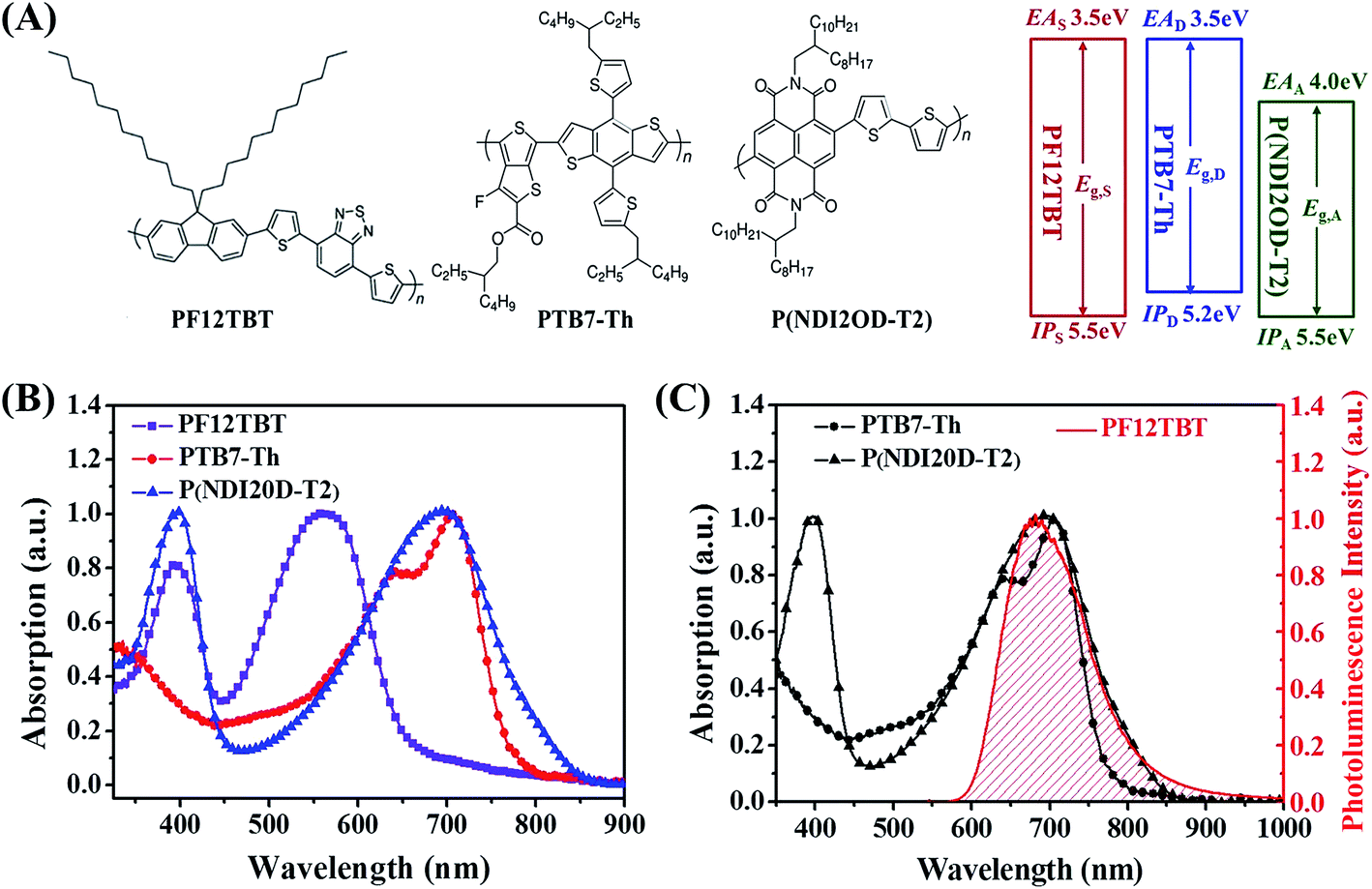 | ||
| Fig. 1 (A) Molecular structures and energy levels of PF12TBT, PTB7-Th and P(NDI2OD-T2). (B) UV-vis absorption spectra of PF12TBT, PTB7-Th, and P(NDI2OD-T2). (C) Optical absorption spectra of PTB7-Th and P(NDI2OD-T2), and steady-state emission spectra of PF12TBT. | ||
To experimentally verify the hypothesis of FRET occurring between PF12TBT and “energy acceptor”, we investigated the PL spectra of neat F12TBT, PTB7-Th, P(NDI2OD-T2) and the mixture of PF12TBT/PTB7-Th and PF12TBT/P(NDI2OD-T2) films with different content of PF12TBT. For the PF12TBT/PTB7-Th blend system as shown in Fig. 2(A), as the PF12TBT content increases, the emission from PTB7-Th centered at 760 nm continuously increases, while the emission of PF12TBT centered at 675 nm was diminished. Similarly, by increasing the amount of PF12TBT in P(NDI2OD-T2), the emission from P(NDI2OD-T2) centerd at 840 nm significantly increases, while the emission of PF12TBT gradually decreases as shown in Fig. 2(B). This suggested the energy can transfer from PF12TBT to both P(NDI2OD-T2) and PTB7-Th through FRET.
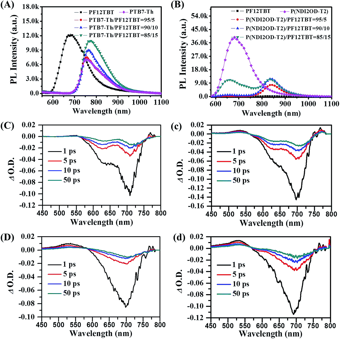 | ||
| Fig. 2 Steady state photoluminescence (PL) spectra of PF12TBT/PTB7-Th blend films (A) and PF12TBT/P(NDI2OD-T2) blend films (B) when excited at 532 nm. Transient spectra of neat PTB7-Th film (C), 15 wt% PF12TBT incorporated PTB7-Th/PF12TBT film (c), neat P(NDI2OD-T2) film (D) and 15 wt% PF12TBT incorporated P(NDI2OD-T2)/PF12TBT film (d) in 1, 5, 10, 50 ps after time zero. | ||
We further establish the FRET using ultrafast pump-probe TA spectra, the neat films and the corresponding blended films were pumped at 400 nm followed by a white light probe. As shown in Fig. 2, the transient spectra contain a main feature, which can be attributed to ground state bleach (GSB). As shown in Fig. 2(C), the GSB peak of PTB7-Th predominantly spans from 575 to 750 nm, and the peak centers at about 705 nm. It is clear that, the intensity of GSB signal at 705 nm was increased after the addition of PF12TBT, the absolute intensity (∣Δ O.D. ∣) of this peak at 1 ps rises from 0.10 (Fig. 2(C)) to 0.14 (Fig. 2(c)). Taylor et al. also observed the similar phenomena in poly(3-hexylthiophene-2,5-diyl) (P3HT)/poly([4,8-bis[(2-ethylhexyl)oxy]benzo[1,2-b:4,5-b′]-dithiophene-2,6-diyl][3-uoro-2-[(2-ethylhexyl)carbonyl]thieno-[3,4-b]thiophenediyl]) (PTB7) blend system, and they ascribed the increased GSB of PTB7 to non-radiative excitonic energy transfer from P3HT.38 Since mainly bleaching of the PF12TBT (as shown in Fig. S2†) does not occur at the wavelength from 600 to 750 nm, this increase of GSB should be ascertained by FRET from PF12TBT to PTB7-Th. As we expected, the analogical variation tendency was also observed in P(NDI2OD-T2) and P(NDI2OD-T2)/PF12TBT films as shown in Fig. 2(D) and (d). The absolute intensity of GSB signal at 1 ps (round about 700 nm and corresponds to P(NDI2OD-T2)) increases from 0.08 to 0.11, which confirmed the existence of FRET from PF12TBT to P(NDI2OD-T2) as well.
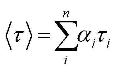
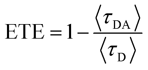
It was confirmed that PF12TBT and “energy acceptor”, i.e. PTB7-Th and P(NDI2OD-T2) are in FRET resonance by both steady PL spectra and transient spectra. Then we would employ the time-correlated single photon counting (TCSPC) spectra of films to calculate the efficiency of FRET as shown in Fig. 3. As we know, FRET predicts a decrease in the excited-state lifetime of “energy donor” after being blended with “energy acceptor”, as FRET introduces an additional nonradiative decay path for the “energy donor” in the system.37,39,40 We probed the fluorescence decay dynamics of PF12TBT film and its blend films, including PF12TBT/PTB7-Th and PF12TBT/P(NDI2OD-T2) blend films. The fluorescence decay was fitted with a two component-exponential function (the specific data are shown in Table S1†), then the mean lifetime was calculated by weighting the amplitude of each component employing eqn (1). The energy transfer efficiency (ETE) is given by eqn (2):39
 | (1) |
 | (2) |
![[thin space (1/6-em)]](https://www.rsc.org/images/entities/char_2009.gif) :5) and PF12TBT/P(NDI2OD-T2) (blending ratio of 95:5) are 2.15 ns, 0.97 ns and 1.36 ns, respectively. After calculation through eqn (2), the ETE values for PF12TBT/PTB7-Th blend system is 54.8% and for PF12TBT/P(NDI2OD-T2) blend system is 36.7%, which suggested that the energy transfer indeed occur from PF12TBT to “energy acceptor” (PTB7-Th, P(NDI2OD-T2)) after the light-absorption by PF12TBT.
:5) and PF12TBT/P(NDI2OD-T2) (blending ratio of 95:5) are 2.15 ns, 0.97 ns and 1.36 ns, respectively. After calculation through eqn (2), the ETE values for PF12TBT/PTB7-Th blend system is 54.8% and for PF12TBT/P(NDI2OD-T2) blend system is 36.7%, which suggested that the energy transfer indeed occur from PF12TBT to “energy acceptor” (PTB7-Th, P(NDI2OD-T2)) after the light-absorption by PF12TBT.
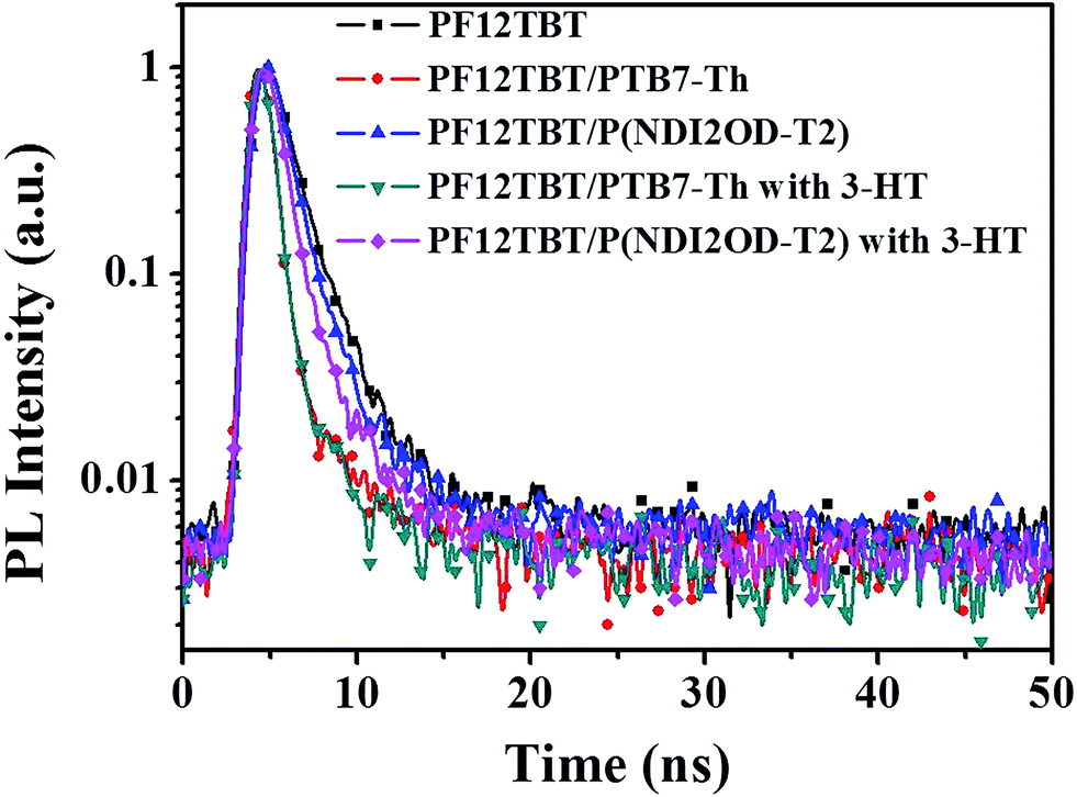 | ||
| Fig. 3 Transient PL decay curves of PF12TBT film, PF12TBT/PTB7-Th blend film, PF12TBT/P(NDI2OD-T2) blend film and the corresponding films with 3-HT. | ||
The detailed photophysics process outlining the possible pathways to current generation after excitation of PF12TBT in this ternary blended system is shown in Scheme 1. First of all, PTB7-Th and P(NDI2OD-T2) are excited to form excitons by photon-absorption in the near-infrared region, in addition, PF12TBT would also absorb photons in visible light region, and form excitons (process 1). Then, the energy would transfer from PF12TBT to “energy acceptor”, exciting extra excitons in both PTB7-Th and P(NDI2OD-T2) phase due to the dual-FRET (process 2). Next, all of the excitons diffused to the interface of PTB7-Th/P(NDI2OD-T2). Due to the energetically favorable between PTB7-Th and P(NDI2OD-T2), the excitons are converted to free charge carriers at the interface (process 3). Finally, the carriers transport to the corresponding electrodes (process 4). This dual-FRET process leads to an increased charge population in PTB7-Th and P(NDI2OD-T2) phase, enhancing current density and device performance, which would be discussed in detail as follows.
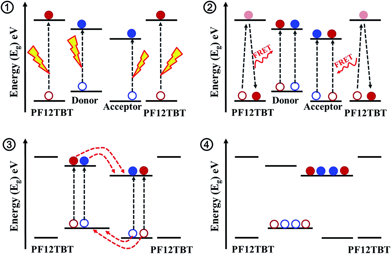 | ||
| Scheme 1 Steps in the photocurrent generation process for PTB7-Th/P(NDI2OD-T2)/PF12TBT blend system. | ||
Reducing phase separation and improving dispersity of PF12TBT
Morphology is critically important to achieve high efficiency for ternary blend BHJ solar cells. In our ternary blend system, the morphology should not only keep the efficient charge dissociation/transport/collection process as in the binary blend BHJ, but also guarantee energy transfer from PF12TBT to “energy acceptor” via dual-FRET. As well known, FRET is a non-radiative energy transfer process that acts through long-range dipole–dipole interactions between “energy donor” and “energy acceptor”. The strength of FRET usually falls in the typical length scale of <10 nm in organic systems.29,37 As a consequence, the idea morphology of this ternary blended system should meet the following requirements according to the characteristic of dual-FRET as shown in the schematic: first, the domain size should be comparable to the length scale of FRET. Besides, PF12TBT should be dispersed in the film uniformly to increase the contact area between PF12TBT and “energy acceptor”.Due to the strong entropy driving force, polymer–polymer blend system generally had a tendency to form large phase separation. However, adding PF12TBT into binary blend system, the scale of phase separation was reduced. To precisely characterize the domain size, the grazing incidence small angle X-ray scattering (GISAXS) for binary and ternary blend films were carried out as shown in Fig. 4(A). After the addition of PF12TBT, the peak in GISAXS of films shifted from 0.43 to 0.50 nm−1, corresponding to a decreased domain size from 14.6 nm to 12.56 nm. The result was in accordance with the atomic force microscopy (AFM) as shown in Fig. 4(B) and (C), in which the root mean-square value is decreased from 1.26 to 1.08 nm after the addition of PF12TBT. The decreased rms value is considered to be a signature of decreased scale of phase separation in blended systems, which has been already confirmed in polymer/fullerene system.41 Thus, not only widening the absorption spectrum but also reducing the scale of phase separation was realized by adding PF12TBT, which could facilitate the photo absorption and exciton dissociation.
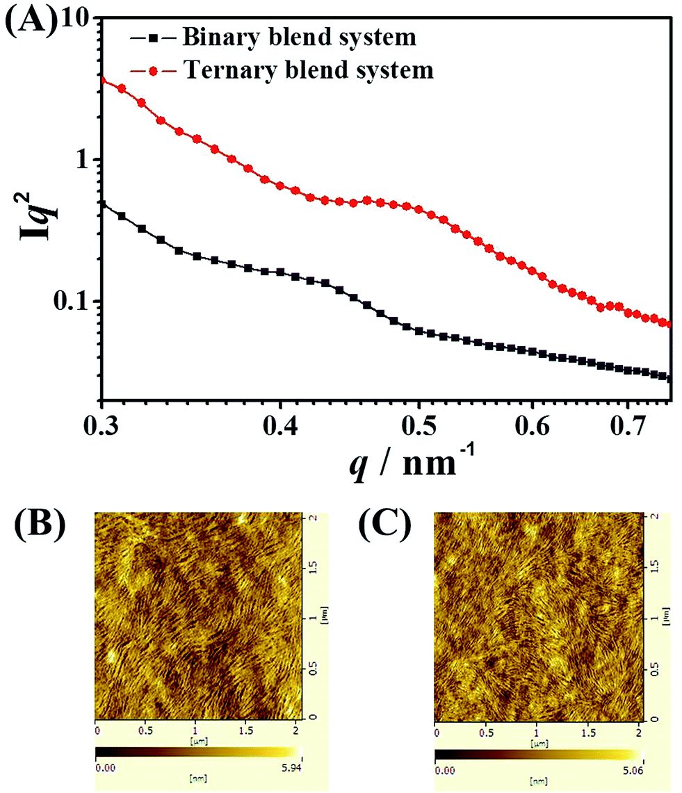 | ||
| Fig. 4 (A) The grazing incidence small angle X-ray scattering (GISAXS) spectra of binary and ternary blend films. Tapping mode AFM height images of binary (B) and ternary (C) blend films. | ||
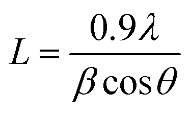
The decreased phase separation may be resulted from more crystal nucleation after the addition of PF12TBT. In order to prove our viewpoint, out-of-plane grazing incidence X-ray diffraction (GIXD) was employed as shown in Fig. 5. In the GIXD pattern for each individual polymer film (as shown in Fig. 5(A)), both the PTB7-Th and P(NDI2OD-T2) give rise to diffraction peaks around at 2θ = 22.5°, which have previously been ascribed to (010) diffraction peak corresponding to π–π stacking between polymer backbones.42 While there is no obvious diffraction signal can be found in the GIXD pattern of PF12TBT, indicating a kind of amorphous polymer feature for PF12TBT. Judging from intensities of these peaks as shown in Fig. 5(B), it is obvious that the crystallinity of the ternary system was enhanced, which is very unusual for ternary PSCs. In addition to crystallinity, the coherence length of PTB7-Th and P(NDI2OD-T2) along the π–π stacking direction were changed as well. The values of coherence length were calculated using the full-width at half-maximum of the scattering peaks based on the Scherrer equation (eqn (3)).43
 | (3) |
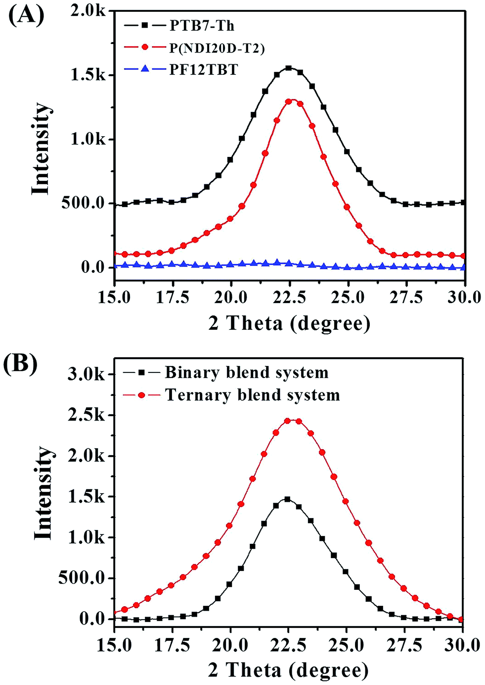 | ||
| Fig. 5 GIXD profile for neat films (A) and for binary and ternary blend films (B). | ||
In addition to domain size, the dispersity of PF12TBT is also a crucial factor to guarantee a high efficiency of dual-FRET in ternary blend system. Herein, 3-hexylthiophene (3-HT, 10 vol%) was selected as the solvent additive to decrease the aggregation of PF12TBT. It has already been recognized in several reports that the solvent–polymer affinities in solution could ultimately affect the morphology of the active layer.44 The solvent–polymer affinities in solution are governed by interaction parameters, χ12. According to Flory–Huggins theory, when the value of χ12 between polymer and solvent is large, polymer molecules tend to contact with the same molecules to reduce energy rather than with solvent molecules, leading to the aggregation of polymer. When the value of χ12 is small, more solvent molecules would interact with polymer molecules, miscibility will thus take place. Specifically, for a certain solvent–polymer system, χ12 can be calculated by eqn (4):45
| χ12 = V(Δδd2 + 0.25Δδp2 + 0.25Δδh2)/RT | (4) |
| Solvent/polymer | δ (J1/2 cm−3/2) | δp (J1/2 cm−3/2) | δh (J1/2 cm−3/2) | δd (J1/2 cm−3/2) |
|---|---|---|---|---|
| PF12TBT | 20.2 | 7.5 | 9.6 | 16.2 |
| Chlorobenzene | 21.9 | 8.9 | 10.9 | 16.8 |
| 3-Hexylthiophene | 20.0 | 6.7 | 9.6 | 16.1 |
Improved photo absorption, exciton dissociation and charge transport
We show the current density–voltage (J–V) characteristics under one sun illumination (as shown in Fig. 6), and device performance parameters are summarized in Table 2. Control devices fabricated from PTB7-Th/P(NDI2OD-T2) blend solutions have a typical PCE of 4.73%, with an open-circuit voltage (VOC) of 0.81 V, a short-circuit current density (JSC) of 10.24 mA cm−2 and a fill factor (FF) of 57%. Here, we note that the device performance for the PTB7-Th/PF12TBT and P(NDI2OD-T2)/PF12TBT blend systems were much lower than that of the PTB7-Th/P(NDI2OD-T2) blend system (Fig. 6 and Table 2), indicating that no effective photoinduced charge transfer occurred in the corresponding blend systems. Incorporating PF12TBT in quantities of 10, 15 and 20 wt% in the PTB7-Th/P(NDI2OD-T2) film led to significant enhancements in the JSC and FF values compared to the control device (Fig. S3 and Table S2†). Films with 15 wt% PF12TBT in the ternary blend resulted in the highest PCE of 5.82%, which displayed a VOC of 0.81 V, JSC of 11.59 mA cm−2 and FF of 62%. It is clear that the value of VOC was nearly constant at around 0.81, while the JSC and FF were significantly improved. After adding 10 vol% 3-HT as solvent additive, the JSC was further increased to 12.28 mA cm−2, resulting peak PCE value of 6.07% (the J–V characteristics of devices containing different volume fraction of 3-HT are shown in Fig. S4 and Table S3†).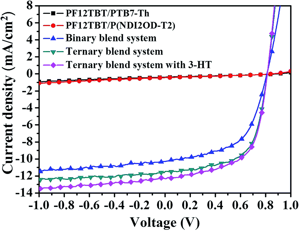 | ||
| Fig. 6 Photocurrent–voltage curves of photovoltaic devices for PF12TBT/P(NDI2OD-T2) blend system, PF12TBT/PTB7-Th blend system, binary blend system, ternary blend system and ternary blend system with 3-HT. | ||
| Device | VOC (V) | JSC (mA cm−2) | FF | PCE (%) | Rsh (Ω cm2) | Rs (Ω cm2) |
|---|---|---|---|---|---|---|
| Binary | 0.81 (0.81 ± 0.00) | 10.24 (10.18 ± 0.13) | 0.57 (0.56 ± 0.01) | 4.73 (4.64 ± 0.12) | 1364 | 536 |
| Ternary | 0.81 (0.81 ± 0.00) | 11.59 (11.43 ± 0.20) | 0.62 (0.61 ± 0.02) | 5.82 (5.78 ± 0.15) | 706 | 318 |
| Ternary with 3-HT | 0.81 (0.81 ± 0.00) | 12.28 (12.21 ± 0.31) | 0.61 (0.59 ± 0.02) | 6.07 (5.93 ± 0.14) | 841 | 393 |
The origin of the enhanced JSC for the ternary blends can be deduced from the external quantum efficiency (EQE) spectra. As shown in Fig. 7(A), for the PTB7-Th/P(NDI2OD-T2) binary device, the EQEs were limited to 53% in the visible range from 550 to 750 nm. For the ternary device, the EQEs were improved noticeably mainly in the visible wavelengths, approaching values as high as 60%. In addition, the integrated JSC values from EQE spectrum for binary, ternary and ternary blended system with 3-HT were 10.58, 11.62 and 12.34 mA cm−2, respectively. This is within 3% of measured JSC values, indicating that the J–V measurements in this work are reliable.
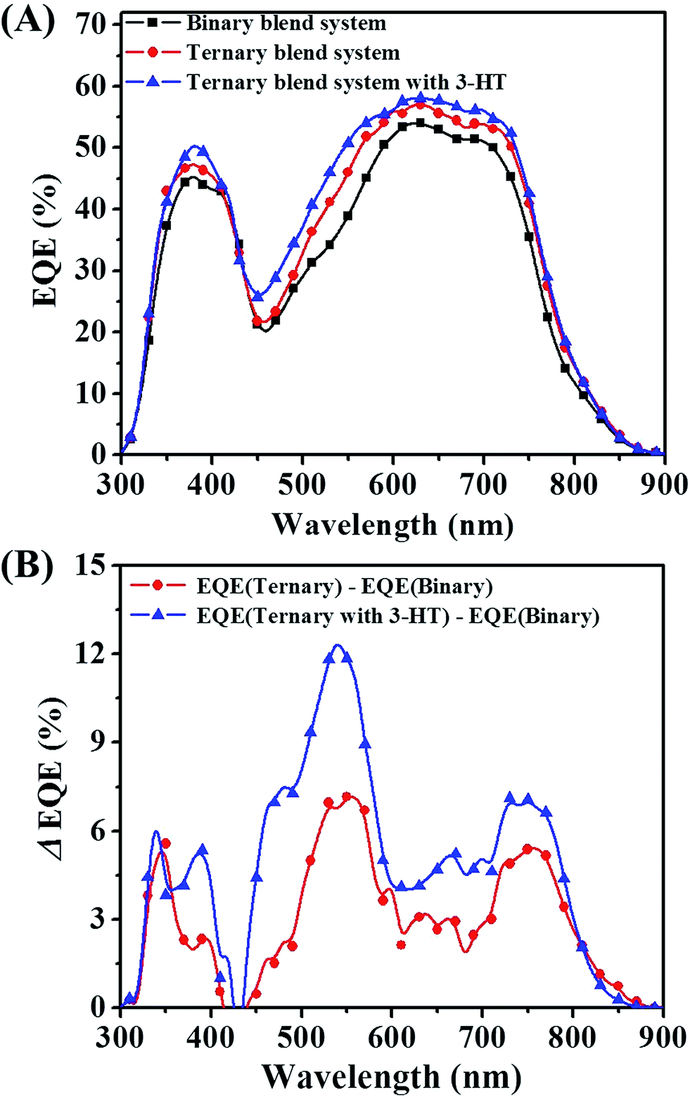 | ||
| Fig. 7 (A) EQE spectra of photovoltaic devices for binary blend system, ternary blend system and ternary blend system with 3-HT. (B) The differential EQE value between ternary blend system and binary blend system, and between ternary blend system with 3-HT and binary blend system. | ||
In order to further illustrate the positive effects of PF12TBT on the device performance, the differential EQE value between binary blend system and ternary blend system is plotted. As shown in Fig. 7(B), compared with the binary blend system, the EQE improvement for ternary blend system primarily originated from two aspects: the widen photon absorption window and the efficient exciton dissociation. PF12TBT has a strong absorption in the range from 300 to 650 nm. Hence, the increasement of EQE in this region should be attributed to the additional photo absorption by PF12TBT, then energy transfer from photoexcited PF12TBT to both PTB7-Th and P(NDI2OD-T2) occurs. Meanwhile, the EQE in the 650–800 nm increases as well. Because incorporation of PF12TBT only led to improved absorption from 300–650 nm region, the increasement in EQE between 650–800 nm should be ascribed to the improved efficiency of exciton dissociation. Nguyen et al. has reported that the upper limit of the P(NDI2OD-T2) exciton diffusion length to be only 1.1 nm,47 which is much smaller than the domain size as we mentioned above, leading to a serious recombination of exciton. When adding PF12TBT, the blended film shows relatively small domains. As a result, more excitons absorbed by PTB7-Th and P(NDI2OD-T2) could diffuse to the interface successfully. While after the addition of 3-HT, the EQE was further improved, especially in the range from 450 to 650 nm, which overlaps with the absorption range of PF12TBT. The improvement should be attributed to the enhanced dispersity of PF12TBT, leading to a more efficient dual-FRET from PF12TBT to “energy accepter”. Thus more exciting excitons would be generated in both PTB7-Th and P(NDI2OD-T2) phase, resulting in an improved JSC.
In the design of ternary blend system, the impact of the third component on the FF is an important consideration owing to a lower FF in original binary system.12 While the FF for our ternary system was increased significantly, up to 61%, which is the highest one in all-polymer ternary blend system to my knowledge. We correlated the FF improvement to decline of series resistance (Rs) as shown in Table 2. The binary device has Rsh at 1364 Ω cm2 and Rs at 536 Ω cm2. Incorporation of PF12TBT lowers Rsh (708 Ω cm2) and Rs (318 Ω cm2). As is well-known, Rsh quantifies the current leakage from pinholes and traps, while Rs is related to the resistive loss of the maximal photocurrent. The decreased Rsh maybe result from the aggregation of PF12TBT, which may act as traps to enhance the current leakage. While the reason for decreased Rsh could be associated to higher crystallinity of both PTB7-Th and P(NDI2OD-T2) after the addition of PF12TBT. The better crystallinity and smaller domain size are benefit for the formation of nanoscale interpenetrating network, which provides the pathway for charge flow and thus translate to higher FF.39,40,48 Adding 3-HT into ternary blend system, the FF declined slightly, implying the interpenetrating network remain effective for charge transport.
Conclusions
We have successfully developed a novel principle for ternary PSCs, i.e. dual-FRET, in which the third component could transfer energy to both the donor and the acceptor. The obvious characteristic of dual-FRET in morphology is the dispersity of the third component, regardless of its location. Employing this principle, an efficient all polymer ternary system by incorporating PF12TBT into a PTB7-Th/P(NDI2OD-T2) binary blend system was established. The steady PL spectra and transient spectra manifested energy could transfer from PF12TBT to both PTB7-Th and P(NDI2OD-T2) efficiently. In comparison with binary blend solar cells, ternary blend solar cells (15 wt% PF12TBT) with 10 vol% 3-HT demonstrated the highest PCE at 6.07%, mainly due to improved light harvesting and optimized morphology. It was found the use of PF12TBT could not only increase photo absorption at visible region but also reduce scale of phase separation and enhance crystallinity. In addition, adding 3-HT as solvent additive into ternary blend system could improve the dispersity of PF12TBT, giving rise to an enhanced efficiency of dual-FRET. As a result, photo absorption, exciton dissociation and charge transport were improved, leading to an increased JSC and FF. Our results substantiated that the use of ternary blend system employing dual-FRET principle is an effective strategy for achieving high performance solar cells. As a result, the location of the third component in the ternary active layer is no more a crucial factor, which would accelerate the application of ternary blend solar cells.Acknowledgements
This work was supported by the National Natural Science Foundation of China (21334006, 51577138), the National Basic Research Program of China (973 Program 2014CB643505) and the Strategic Priority Research Program of the Chinese Academy of Sciences (Grant No. XDB12020300). We also thank Shanghai Synchrotron Radiation Facility (SSRF) BL14U1 for GISAXS measurements.References
- M. Corazza, N. Rolston, R. H. Dauskardt, M. Beliatis, F. C. Krebs and S. A. Gevorgyan, Adv. Energy Mater., 2016, 6, 1501927 CrossRef.
- Q. S. An, F. J. Zhang, Q. Q. Sun, J. Wang, L. L. Li, J. Zhang, W. H. Tang and Z. B. Deng, J. Mater. Chem. A, 2015, 3, 16653–16662 CAS.
- M. Zhang, F. J. Zhang, Q. S. An, Q. Q. Sun, W. B. Wang, J. Zhang and W. H. Tang, Nano Energy, 2016, 22, 241–254 CrossRef CAS.
- Y. Z. Lin and X. W. Zhan, Acc. Chem. Res., 2016, 49, 175–183 CrossRef CAS PubMed.
- M. Wang, H. Wang, T. Yokoyama, X. Liu, Y. Huang, Y. Zhang, T. Q. Nguyen, S. Aramaki and G. C. Bazan, J. Am. Chem. Soc., 2014, 136, 12576–12579 CrossRef CAS PubMed.
- Q. S. An, F. J. Zhang, Q. Q. Sun, M. Zhang, J. Zhang, W. H. Tang, X. X. Yin and Z. B. Deng, Nano Energy, 2016, 26, 180–191 CrossRef CAS.
- C. W. Tang, Appl. Phys. Lett., 1986, 48, 183–185 CrossRef CAS.
- S. Zhang, L. Ye and J. Hou, Adv. Energy Mater., 2016, 6, 1502529 CrossRef.
- W. Ma, G. Yang, K. Jiang, J. H. Carpenter, Y. Wu, X. Meng, T. McAfee, J. Zhao, C. Zhu, C. Wang, H. Ade and H. Yan, Adv. Energy Mater., 2015, 5, 1501400 CrossRef.
- L. Nian, K. Gao, F. Liu, Y. Kan, X. Jiang, L. Liu, Z. Xie, X. Peng, T. P. Russell and Y. Ma, Adv. Mater., 2016, 28, 8184–8190 CrossRef CAS PubMed.
- X. Lin, Y. Yang, L. Nian, H. Su, J. Ou, Z. Yuan, F. Xie, W. Hong, D. Yu, M. Zhang, Y. Ma and X. Chen, Nano Energy, 2016, 26, 216–223 CrossRef CAS.
- Y. J. Hwang, B. A. E. Courtright, A. S. Ferreira, S. H. Tolbert and S. A. Jenekhe, Adv. Mater., 2015, 27, 4578–4584 CrossRef CAS PubMed.
- H. Kang, K. H. Kim, J. Choi, C. Lee and B. J. Kim, ACS Macro Lett., 2014, 3, 1009–1014 CrossRef CAS.
- H. Yao, R. Yu, T. J. Shin, H. Zhang, S. Zhang, B. Jang, M. A. Uddin, H. Y. Woo and J. Hou, Adv. Energy Mater., 2016, 6, 1600742 CrossRef.
- L. Ye, X. Jiao, M. Zhou, S. Zhang, H. Yao, W. Zhao, A. Xia, H. Ade and J. Hou, Adv. Mater., 2015, 27, 6046–6054 CrossRef CAS PubMed.
- D. Mori, H. Benten, H. Ohkita and S. Ito, J. Mater. Chem. A, 2016, 4, 5340–5365 Search PubMed.
- D. Mori, H. Benten, I. Okada, H. Ohkitaab and S. Ito, Energy Environ. Sci., 2014, 7, 2939–2943 CAS.
- L. Gao, Z. G. Zhang, L. Xue, J. Min, J. Zhang, Z. Wei and Y. Li, Adv. Mater., 2016, 28, 1884–1890 CrossRef CAS PubMed.
- B. Kang, R. Kim, S. B. Lee, S. K. Kwon, Y. H. Kim and K. Cho, J. Am. Chem. Soc., 2016, 138, 3679–3686 CrossRef CAS PubMed.
- S. Nam, S. Woo, J. Seo, W. H. Kim, H. Kim, C. R. McNeill, T. J. Shin, D. D. C. Bradley and Y. Kim, ACS Appl. Mater. Interfaces, 2015, 7, 15995–16002 CAS.
- M. Schubert, B. A. Collins, H. Mangold, I. A. Howard, W. Schindler, K. Vandewal, S. Roland, J. Behrends, F. Kraffert, R. Steyrleuthner, Z. Chen, K. Fostiropoulos, R. Bittl, A. Salleo, A. Facchetti, F. Laquai, H. W. Ade and D. Neher, Adv. Funct. Mater., 2014, 24, 4068–4081 CrossRef CAS.
- S. H. Liao, H. J. huo, Y. S. Cheng and S. A. Chen, Adv. Mater., 2013, 23, 4766–4771 CrossRef PubMed.
- Z. Li, X. Xu, W. Zhang, X. Meng, W. Ma, A. Yartsev, O. Inganäs, M. R. Andersson, R. A. J. Janssen and E. Wang, J. Am. Chem. Soc., 2016, 138, 10935–10944 CrossRef CAS PubMed.
- T. Liu, L. J. Huo, X. B. Sun, B. B. Fan, Y. H. Cai, T. Kim, J. Y. Kim, H. Choi and Y. M. Sun, Adv. Energy Mater., 2015, 6, 1502109 CrossRef.
- J. Min, Z. G. Zhang, S. Zhang and Y. Li, Chem. Mater., 2012, 24, 3247–3254 CrossRef CAS.
- L. Gao, Z. G. Zhang, L. Xue, J. Min, J. Zhang, Z. Wei and Y. Li, Adv. Mater., 2016, 28, 1884–1890 CrossRef CAS PubMed.
- S. H. Zhang, L. J. Zuo, J. H. Chen, Z. Q. Zhang, J. Q. Mai, T. Lau, X. H. Lu, M. M. Shi and H. Z. Chen, J. Mater. Chem. A, 2016, 4, 1702–1707 CAS.
- Y. Xiao, H. Wang, S. Zhou, K. Yan, W. Xie, Z. Guan, S.-W. Tsang and J.-B. Xu, Nano Energy, 2016, 19, 476–485 CrossRef CAS.
- H. Benten, D. Mori, H. J. Xu, H. Ohkita and S. Ito, Energy Environ. Sci., 2016, 9, 135–140 CAS.
- R. Zhang, H. Yang, K. Zhou, J. D. Zhang, J. G. Liu, X. H. Yu, R. B. Xing and Y. C. Han, J. Polym. Sci., Part B: Polym. Phys., 2016, 54, 1811–1819 CrossRef CAS.
- L. Y. Lu and L. P. Yu, Adv. Mater., 2014, 26, 4413–4430 CrossRef CAS PubMed.
- Q. S. An, F. J. Zhang, J. Zhang, W. H. Tang, Z. B. Deng and B. Hu, Energy Environ. Sci., 2016, 9, 281–322 Search PubMed.
- L. Yang, L. Yan and W. You, J. Phys. Chem. Lett., 2013, 4, 1802–1810 CrossRef CAS PubMed.
- Z. Wang, Y. Zhang, J. Zhang, Z. Wei and W. Ma, Adv. Energy Mater., 2016, 6, 1502456 CrossRef.
- K. Cnops, B. P. Rand, D. Cheyns, B. Verreet, M. A. Empl and P. Heremans, Nat. Commun., 2014, 5, 3406 Search PubMed.
- B. M. Savoie, S. Dunaisky, T. J. Marks and M. A. Ratner, Adv. Energy Mater., 2015, 5, 1400891 CrossRef.
- V. Gupta, V. Bharti, M. Kumar, S. Chand and A. J. Heeger, Adv. Mater., 2015, 27, 4398–4404 CrossRef CAS PubMed.
- T. Goh, J.-S. Huang, B. Bartolome, M. Y. Sfeir, M. Vaisman, M. L. Lee and A. D. Taylor, J. Mater. Chem. A, 2015, 3, 18611–18621 CAS.
- T. Goh, J.-S. Huang, E. A. Bielinski, B. A. Thompson, S. Tomasulo, M. L. Lee, M. Y. Sfeir, N. Hazari and A. D. Taylor, ACS Photonics, 2015, 2, 86–95 CrossRef CAS.
- T. Goh, J.-S. Huang, X. K. Li, M. Y. Sfeir, E. A. Bielinski, S. Tomasulo, M. L. Lee, N. Hazari and A. D. Taylor, Nat. Photonics, 2013, 7, 479–485 CrossRef.
- J. G. Liu, S. Y. Shao, H. F. Wang, K. Zhao, L. J. Xue, X. Gao, Z. Y. Xie and Y. C. Han, Org. Electron., 2010, 11, 775–783 CrossRef CAS.
- K. Zhou, R. Zhang, J. G. Liu, M. G. Li, X. H. Yu, R. B. Xing and Y. C. Han, ACS Appl. Mater. Interfaces, 2015, 7, 25352–25361 CAS.
- J. G. Liu, L. Chen, B. R. Gao, X. Cao, Y. C. Han, Z. Y. Xie and L. X. Wang, J. Mater. Chem. A, 2013, 1, 6216–6225 CAS.
- E. Pavlopoulou, C. S. Kim, S. S. Lee, Z. Chen, A. Facchetti, M. F. Toney and Y.-L. Loo, Chem. Mater., 2014, 26, 5020–5027 CrossRef CAS.
- F. Machui and C. J. Brabec, Semicond. Polym. Compos., 2012 Search PubMed.
- K. Zhou, J. G. Liu, M. G. Li, X. H. Yu, R. B. Xing and Y. C. Han, J. Polym. Sci., Part B: Polym. Phys., 2015, 53, 288–296 CrossRef CAS.
- Z. Li, J. D. A. Lin, H. Phan, A. Sharenko, C. M. Proctor, P. Zalar, Z. Chen, A. Facchetti and T.-Q. Nguyen, Adv. Funct. Mater., 2014, 24, 6989–6998 CrossRef CAS.
- J. G. Liu, Q. J. Liang, H. Y. Wang, M. G. Li, Y. C. Han, Z. Y. Xie and L. X. Wang, J. Phys. Chem. C, 2014, 118, 4585–4595 CAS.
Footnote |
| † Electronic supplementary information (ESI) available. See DOI: 10.1039/c7ra00244k |
| This journal is © The Royal Society of Chemistry 2017 |