
 Open Access Article
 This Open Access Article is licensed under a
 Creative Commons Attribution 3.0 Unported Licence
Design and synthesis of dodecahedral carbon nanocages incorporated with Fe3O4†
Siyuan Xianga,
Yanhong Shib,
Kai Zhang *a,
Yixin Chena,
Rui Gea,
Ce Wua,
Haizhu Sunb and
Bai Yanga
*a,
Yixin Chena,
Rui Gea,
Ce Wua,
Haizhu Sunb and
Bai Yanga
aState Key Laboratory of Supramolecular Structure and Materials, College of Chemistry, Jilin University, Changchun 130012, People's Republic of China. E-mail: zk@jlu.edu.cn
bFaculty of Chemistry, Northeast Normal University, Changchun 130024, China
First published on 27th February 2017
Abstract
Novel dodecahedral carbon nanocages (NCs) modified with Fe3O4 nanoparticles (Fe3O4/C NCs) were constructed by utilizing a zeolitic imidazolate framework (ZIF-8) as the template and polydopamine (PDA) as the carbon source. The obtained nanocages not only display specific morphology with controllable feature structures, but also possess a large surface area and inner cavity. This unique structure of the nanocages and special synthesis approach make Fe3O4 NPs homogenously distributed in the system, which further enriched the function of the carbon nanocages. Due to the integrated functional nanoparticles and large interior of such specific structures, the as-prepared Fe3O4/C NCs are further used as anode materials in lithium ion batteries (LIBs), which exhibit high activity in lithiation/delithiation cycling process and stable capacity retention. The nanocages we prepared may provide a train of thought to construct a series of hollow carbon nanostructures with functional materials incorporated.
1. Introduction
Hollow nanocages have attracted great attention because of their unique properties such as low density, high surface area, shell permeability, chemical and physical stability, etc.1,2 They have successfully found applications in many fields ranging from delivery vehicles to batteries.3–5 Various nanocages have been prepared by template methods, supramolecular assembly, galvanic replacement, etc.6–8 However, there still exist some issues to be addressed, such as complicated synthesis, tedious post-treatment procedures, high cost, etc. In addition, nanocages with non-sphere shapes and regular interiors are still difficult to obtain. These unique nanocages are of particular interests due to their special physical properties and can serve as building blocks for assembly into hierarchical synthetic architectures. Moreover, they bring advantages that aren't able to be achieved through traditional round shapes driven by surface-tension.9 Therefore, it is significant to obtain nanocages with specific morphology and controllable properties.To solve these problems, researchers have developed approaches to synthesize anisotropic nanocages with different structures. For instance, Lou's group successfully established a synthetic approach of inorganic nanocages via a templating method.5,9–12 In addition, we exploited a novel ‘chelation competition induced polymerization’ (CCIP) method to prepare hollow polydopamine nanocontainers.13 These nanocages not only possess the inherent properties of materials, but also exhibit some new functions which are derived from the new hollow structure. Moreover, after annealing under inert gas, these polymer-based hollow structures can be further transformed into carbon nanocages.
Nowadays carbon materials are more and more popular due to their good electronic conductivity, high availability and cost efficiency and shown great potential in many fields like lithium-ion batteries (LIBs).14–16 In order to meet the ever-growing demands of market, anode materials are no longer limited to traditional graphite electrodes (theoretical capacity of 370 mA h g−1), various carbon materials with different structures were prepared.17–19 Moreover, nanocomposites integrated carbon with other materials possessing higher theoretical capacity (such as metal oxide, Fe3O4, 924 mA h g−1) were also investigated.18,20–22 Compared to the solid one, carbon nanostructures with hollow interior have shown much more advantages in LIBs since they will facilitate electrolyte transportation, lithium ion diffusion, provide more space to alleviate the stain arising from Li insertion/removal and enlarge the surface to volume ratio, resulting in faster reaction kinetics and higher specific capacity.20–22 For example, Xiong group has prepared a polyhedral carbon nanocages by carbonizing ZIF-8@ZIF-67 core–shell crystals. Such bi-metal embedded N-doped nanocages show an initial discharge capacity of 809 mA h g−1 and a capacity retention of 702 mA h g−1 after 400 cycles at a current density of 0.2 A g−1.23 Despite of the achieved progress, it is still very important for us to construct more novel functional nanostructures as anode materials for LIBs.
In this work, a novel kind of dodecahedral carbon nanocages was successfully constructed. The method we developed exactly provided an effective way to prepare a unique carbon nanocage structure by using zeolitic imidazolate framework (ZIF-8) as template and polydopamine as carbon resource. The obtained carbon nanocages not only maintain the shape of ZIF-8 with highly uniform shells and tunable sizes, but also make it easy to introduce functional nanoparticles (e.g. Fe3O4 NPs in this work, named Fe3O4/C NCs) into the system. The carbon nanocage matrix has more space for the volume expansion of Fe3O4 NPs due to their large inner cavity and surface area, as well as provide a continue network for ion and electron transfer by embedding nanoparticles into the system. Moreover, N-doped is easily realized by choosing PDA as carbon resource, further improving the conductivity of the nanocages. The electrochemical performance as anode materials of LIBs was evaluated. The results show good cyclic performance and stability, indicating their promising application in energy fields.
2. Experimental section
2.1 Materials
Iron(III) acetylacetonate (Fe(acac)3, 97%), dibenzyl ether (≥98%, GC), 1,2-hexadecanediol, oleic acid (≥99%, GC), oleylamine (OA) (≥98%), polyvinylpyrrolidone (Mw 40![[thin space (1/6-em)]](https://www.rsc.org/images/entities/char_2009.gif) 000), zinc nitrate hexahydrate (Zn(NO3)2·6H2O), 2-methylimidazole (99%) and dopamine hydrochloride were purchased from Sigma-Aldrich. Hexane, chloroform, ethanol were purchased from Beijing Chemical Works.
000), zinc nitrate hexahydrate (Zn(NO3)2·6H2O), 2-methylimidazole (99%) and dopamine hydrochloride were purchased from Sigma-Aldrich. Hexane, chloroform, ethanol were purchased from Beijing Chemical Works.
2.2 Preparation of OA-stabilized Fe3O4 nanoparticles
OA-stabilized Fe3O4 NPs were prepared following the procedure of Sun et al.24 The as-prepared NPs were precipitated with ethanol, washed several times and centrifuged at 7000 rpm for 10 min. Then Fe3O4 NPs were re-dispersed in chloroform.2.3 Preparation of Fe3O4/ZIF-8 nanostructures
Before the encapsulation procedure, OA-stabilized Fe3O4 NPs were firstly modified with surfactant PVP. In brief, Fe3O4 NPs were precipitated with ethanol, and centrifuged at 7000 rpm for 10 min. A solution of PVP (Mw = 40000) in chloroform (20 mg mL−1) was used to re-dispersed the NPs. Then the mixture was kept for 24 hours, the PVP-modified Fe3O4 NPs were precipitated with hexane and collected by centrifugation at 7000 rpm for 10 min. The NPs were washed with chloroform for several times to remove the excess free PVP. And then the sample was re-dispersed in methanol.
In the encapsulation procedure, methanol was used as solvent. 10 mL solution of 2-methylimidazole (25 mM) and 10 mL 25 mM Zn(NO3)2·6H2O (containing 1 mL PVP-stabilized Fe3O4 NPs methanol solution) were mixed and then allowed to react at room temperature for 1 hour without stirring. The product was collected by centrifugation at 5000 rpm for 10 min, washed several times with methanol, and final dispersed in 3.0 mL methanol.
2.4 Preparation of Fe3O4/PDA NCs
3.0 mL Fe3O4/ZIF-8 methanol solution was mixed with 4.5 mL methanol and 1.5 mL dopamine (20 mM in methanol). The mixture was stirring and refluxing at 60 °C for 12 h, the color of which turned to black gradually. The product was collected by centrifugation at 6000 rpm for 10 min and washed with methanol for several times, and freeze-drying overnight.2.5 Preparation of Fe3O4/C NCs
Fe3O4/PDA NCs powder was thermal annealed at 550 °C under N2 flow with 3 °C min−1 for 4 h.2.6 Electrochemical measurements
The working electrodes were prepared by mixing the Fe3O4/C NCs, acetylene black, and poly(vinyldifluoride) (PVDF) at a weight ratio of 80:10:10 in electrolyte of dimethyl carbonate (DMC) and ethylene carbonate (EC) (1:1 v/v), pasting the mixture on pure Cu foil and dried at 100 °C under vacuum for 10 h. The discharge–charge measurements were carried out at several different current densities between the cut off potentials of 0.01 and 3 V using Land CT2001A battery test system. Cyclic voltammogram (CV) measurements were performed on CHI750E electrochemical workstation.
2.7 Characterization
Transmission electron microscopy (TEM) images were collected on a Hitachi H-800 electron microscope operated at 200 kV with a CCD camera. High-resolution TEM images and mapping images were recorded using a JEM-2100F electron microscope at an acceleration voltage of 200 kV with a CCD camera. Scanning electron microscope (SEM) images were taken with a JEOL FESEM 6700F electron microscope with primary electron energy of 3 kV. The samples were sputtered with a thin layer of Pt prior to imaging. Inductively Coupled Plasma (ICP) results were conducted by OPTIMA 3300DV spectrometer. X-ray diffraction (XRD) analysis was performed by X-ray diffractometer, Model Rigaku Ru-200b, using a nickel-filtered Cu Kα radiation and the data were collected from 10° to 80°. X-ray photoelectron spectroscopic (XPS) analysis was done on an ESCALAB 250 spectrometer. Raman spectrum was recorded using a Horiba Jobin-Yvon micro Raman spectrometer, equipped with a microscope and a laser of 633 nm as the excitation source. N2 adsorption–desorption measurements were conducted by Micromeritics ASAP 2010 instrument. The pore size distribution was calculated by the Barrett–Joyner–Halenda (BJH) method. And the specific surface area was calculated by using BJH and Brunauer–Emmett–Teller (BET) method. Hysteresis loop was tested by SQUID-VSM system. Magnetic measurements were performed using a SQUID magnetometer (SQUID-MPMS-XL) at 300 K by cycling the magnetic field between −30 and 30 kOe.The main text of the article should appear here with headings as appropriate.
3. Results and discussion
3.1 Fabrication and regulation of Fe3O4/C NCs
The synthesis process of dodecahedral Fe3O4/C NCs is schematically illustrated in Scheme 1. Firstly, OA-stabilized Fe3O4 nanoparticles (NPs), obtained through hydrothermal method, were firstly washed and modified with polyvinylpyrrolidone (PVP).24 The Fe3O4/ZIF-8 nanostructure could be easily obtained by adding PVP-Fe3O4 NPs into the mixture of Zn(NO3)2 and 2-methylimidazole.25 Then, dopamine (DA) was added to react with the as-prepared Fe3O4/ZIF-8 and refluxed for 7 h. During this process, the Zn2+ in ZIF-8 was grabbed by DA via its catechol group, leading the disassembly of the template and releasing 2-methylimidazole which triggered the polymerization of DA.13 Finally, the nanostructure got hollowed and Fe3O4/polydopamine nanocages (Fe3O4/PDA NCs) formed. After dried in vacuum and annealed at 550 °C under N2 flow (3 °C min−1 for 4 h), the polymer shell of the PDA nanocages was transformed into a carbon layer and formed Fe3O4/C NCs. In our method, the hollow C nanocage was prepared without extra template removal, and the functionalization of the C nanocage, such as incorporating Fe3O4 NPs to the system is easily achieved through surfactant modification.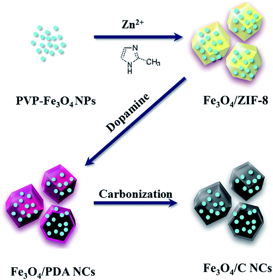 | ||
| Scheme 1 Schematic illustration of the synthesis of Fe3O4/C NCs. | ||
Electron microscopy measurements were conducted to monitor the product morphology changes in each preparation process. As shown in Fig. S1,† OA-stabilized Fe3O4 NPs were about 5 nm.24 After forming Fe3O4/ZIF-8, the nanostructure was about 350 nm with many Fe3O4 NPs loading in and on (Fig. 1A). The dodecahedral shape of Fe3O4/ZIF-8 is very similar to that of pure ZIF-8, suggesting that incorporating functional nanoparticles have no obvious effects to the morphology of ZIF-8 nanostructure. With the reaction proceeding, the color of the solution turned gradually from brownish (Fe3O4/ZIF-8) to black, finally forming the hollow nanocages (Fig. 1B). The obtained Fe3O4/PDA NCs are ca. 364 nm with ca. 30 nm of PDA shell.
 | ||
| Fig. 1 TEM images of Fe3O4/ZIF-8 (A), Fe3O4/PDA NCs (B), Fe3O4/C NCs (C) and SEM image of Fe3O4/C NCs (D). Insets: TEM images of Fe3O4/ZIF-8, Fe3O4/PDA NCs, Fe3O4/C NCs and SEM image of a broken Fe3O4/C NCs with high magnification. The scale bar in the insets is 200 nm. | ||
The hollowing process was monitored by TEM images in Fig. 2. With the time processing, the original solid Fe3O4/ZIF-8 was firstly split to ‘core–shell’ structure (Fig. 2B). Then the ‘core’ part of the structure was getting smaller and smaller, and totally disappeared (Fig. 2C and D). Fe3O4/C NCs were prepared by further annealing Fe3O4/PDA NCs under N2 flow. As shown in Fig. 1C, the obtained NCs maintained the original shape of ZIF-8 nanostructures. SEM image also shows the appearance of Fe3O4/C NCs, which perfectly retained the dodecahedral morphology (Fig. 1D). The large hollow inner cavity observed from a typical broken structure also proves the formation of nanocages (inset in Fig. 1D). Optical photographs in Fig. S1B† shows that when placing a magnet, all the Fe3O4/C NCs the powder was attracted to the wall of glass vial, suggesting their good magnetism of the NCs. Moreover, the completely reversible M (H) hysteresis curve suggests the superparamagnetic structure of Fe3O4/C NCs (Fig. S1D†), which is consistent with Fe3O4 NPs we used (Fig. S1C†). Elemental mapping measurements were also conducted to see the distribution of Fe3O4 in both Fe3O4/PDA NCs and Fe3O4/C NCs. As shown in Fig. S2,† the element C presents a hollow dodecahedral shape and distributes throughout the structure (red), while Fe (green) major distributed on the backbone of the carbon nanocages. All these results prove that Fe3O4 NPs are retained in the final products even experiencing hollowing process. Inductively coupled plasma (ICP) results present the content of metallic elements in Table S2,† suggesting the loading capacity of Fe3O4 could reach 20.3% of the Fe3O4/C NCs. Series of Fe3O4/C NCs were obtained by precisely controlling the reaction condition. For example, the size of the NCs could be regulated by changing that of ZIF-8 templates. As shown in Fig. 3, Fe3O4/C NCs from down-to-100 nm (90 nm) to over 500 nm (561 nm) could be achieved. Moreover, the loading capacity of the Fe3O4 NPs could also be modulated (Fig. S3†) and the functional nanoparticles is replaceable. These controllable nanocages may meet the demands of application in variety of fields by choosing suitable sizes and functionalities in the future.
 | ||
| Fig. 2 TEM images of Fe3O4/PDA NCs with the reaction time of 0 h (A), 2 h (B), 4 h (C) and 7 h (D). | ||
 | ||
| Fig. 3 TEM images of Fe3O4/ZIF-8 nanostructure with different sizes (97 nm A, 350 nm C and 574 nm E) and the corresponding Fe3O4/C NCs (90 nm B, 332 nm D and 561 nm F). | ||
3.2 Characterization of Fe3O4/C NCs
Raman spectroscopy is displayed to characterize the nature of Fe3O4/C NCs (Fig. 4). Two major peaks at ca. 1336 and 1580 cm−1 are corresponding to the ‘D’ and ‘G’ bands of carbon materials, respectively.22 The intensity ratio of these two bands (ID/IG) reaches 1.47, suggesting that the presence of carbon in the NCs is in the form of amorphous structure. Besides, the peaks at ca. 310, 534, and 626 cm−1 are assigned to Fe3O4 NPs, meanwhile ca. 426, 559, and 1100 cm−1 belong to ZnO, which is further proved by the results of powder X-ray diffraction (XRD) measurements in Fig. 4B.26,27 Fe3O4/C NCs exhibit strong wurtzite patterns of ZnO (red line, JCPDS card number 36-1451), which is formed during the annealing process, and the content is 37.4% (Table S2†).28 HRTEM also prove the crystallinity of ZnO (Fig. S4†). Comparing to Fe3O4/PDA NCs, no obvious structure changes were observed in Fe3O4/C NCs, suggesting that the existence of ZnO has no effect on the structure of our system. It is worth noting that only a weak peak (ca. 35°) belongs to Fe3O4 (green dashed circle, JCPDS no. 65-3107) was observed in the pattern. This is due to the originally low intensity of pure Fe3O4 (black line), together with the shielding effect of the ZnO.22 A diffuse scattering peak observed at around 20° is attributed to the amorphous form of carbon nanocages, which is consisted with the Raman spectroscopy results (Fig. 4A). The chemical composition of the Fe3O4/C NCs was characterized by X-ray photoelectron spectroscopy (XPS). As shown in Fig. 4C, an overall XPS spectrum of Fe3O4/C NCs indicates the presence of C, Fe, O, N and Zn elements in the NCs, and the peak at 711.2 eV can be assigned to the Fe 2p3/2, referencing to the standard XPS spectrum for Fe3O4.29 In the high-resolution N 1s spectrum (Fig. 4D), two peaks observed at ∼398.6 eV and 400.7 eV are identified to C–N and C![[double bond, length as m-dash]](https://www.rsc.org/images/entities/char_e001.gif) N, indicating N is doped in the structure of carbon nanocages. It is derived from the amine group in the PDA, which also serves as carbon source in our system, and the doping content is 2.8%, as shown in Table S1.†
N, indicating N is doped in the structure of carbon nanocages. It is derived from the amine group in the PDA, which also serves as carbon source in our system, and the doping content is 2.8%, as shown in Table S1.†
 | ||
| Fig. 4 Raman spectrum of Fe3O4/C NCs (A), XRD patterns of Fe3O4 (black line) and Fe3O4/C NCs (red line) (B), XPS spectrum (C) and N 1s spectrum (D) of Fe3O4/C NCs. | ||
Such doping is beneficial to improve the electrical conductivity and surface hydrophilicity, further increasing the potential application of Fe3O4/C NCs in electrochemistry field. During the formation of Fe3O4/PDA NCs, the disassembling process of ZIF-8 template demonstrates the permeability of PDA shell for the mass diffusion through the interstices (Fig. 2). After the carbonization process, the porous property of Fe3O4/C NCs was investigated through N2 adsorption–desorption isotherm (Fig. 5). The nanocages display a typical IV-type isotherm, indicating the presence of mesopores. An obvious H3-type hysteresis loop is observed after P/P0 reaching 0.5, due to the adsorption of N2 in the inner cavities of Fe3O4/C NCs.22 The BET surface area is 383.9 m2 g−1, and the pore sizes of the nanocages are mainly focus on ca. 3.8 nm and 6.2 nm, deriving from the formation of nanocage and the gas release during the carbonization of the polymer shell. Such relatively high surface area will provide highly permeable for mass diffusion of electrolyte, improving the interaction between the nanocages and solution.
 | ||
| Fig. 5 Nitrogen adsorption–desorption isotherms of Fe3O4/C NCs. Inset: BJH desorption dV/dw pore width of Fe3O4/C NCs. | ||
3.3 Lithium storage properties of Fe3O4/C NCs
The Fe3O4 was chosen to incorporate in the nanocages because it has been regarded as one of promising anode materials for rechargeable LIBs. It possesses high theoretical capacity (∼927 mA h g−1), natural abundance and nontoxicity.26,30–32 Motivated by such intriguing structure, we evaluated the electrochemical properties of the obtained Fe3O4/C NCs. Fig. 6A shows the representative cyclic voltammograms (CVs) of the sample between 10 mV and 3 V at a scan rate of 0.1 mV s−1. A relatively weak reduction peak is observed around 0.1 V, which responses to the multistep reduction processes from ZnO to Zn0 and the generation of Li–Zn alloy.33,34 The peak around 0.5 V in the first scan of the electrode is attributed to the formation of the solid electrolyte interphase (SEI) layer. The CV curves at the second and third cycles show a broad peak at 0.5–1.0 V, corresponding to the reduction of ZnO and Fe3O4 and the formation of amorphous Li2O.33 The reduction peaks at ∼0.9 V in the first cycle and ∼0.83 V at 2nd scan are ascribed to the reduction of Fe3O4 and the formation of SEI layer. There are three adjacent small oxidation peaks appearing below 1 V in the following anodic scan, which may be indicated as the multistep dealloying process of Li–Zn alloy (LiZn, Li2Zn, LiZn2, and Li2Zn5).33 In addition, the smooth and broad oxidation peak around 1.3–1.7 V may be ascribed to the decomposition of Li2O and the oxidation of Fe0.25 The little changes in these oxidation peaks indicate a good reversibility of the electrochemical reaction.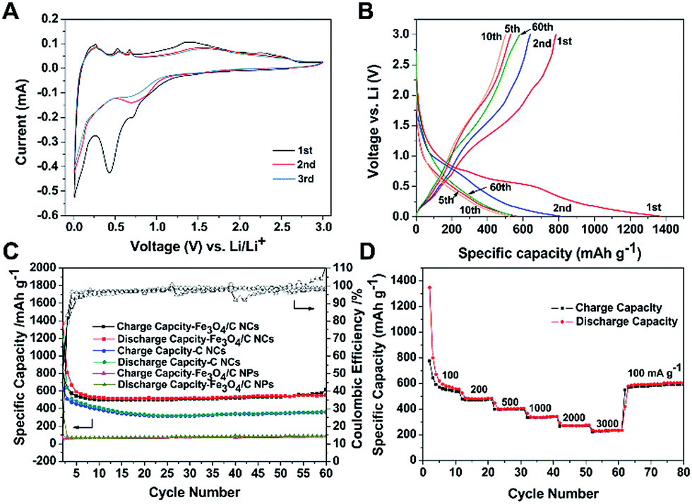 | ||
| Fig. 6 Cyclic voltammograms of Fe3O4/C NCs between 10 mV and 3 V at a scan rate of 0.1 mV s−1 (A), charge–discharge voltage profiles (B), cycling performance and the corresponding CE of the Fe3O4/C NCs compared to C NCs and solid Fe3O4/C NPs at 100 mA g−1 (C) and rate capability of the Fe3O4/C NCs at various current rates (D). | ||
The charge–discharge voltage profiles of Fe3O4/C NCs with different cycles at 100 mA g−1 in the voltage range of 0.01–3.0 V are shown in Fig. 6B. In the first cycle, Fe3O4/C NCs exhibit an initial discharge capacity of 1370 mA h g−1 and a charge capacity of 789 mA h g−1, with an initial coulombic efficiency (CE) of 57.6% based on the total mass of the sample. The capacity loss in the first cycle may be attributed to the irreversible processes such as the formation of SEI layer and amorphous Li2O, trapped Li+ in the inner cavity of the Fe3O4/C NCs and the decomposition of the electrolyte, etc.24,25 Fig. 6C shows the cycling performance and the corresponding CE of the Fe3O4/C NCs. The first charge and discharge capacity are 789–1370 mA h g−1 and gradually remain at 584 mA h g−1 with the prolonging of cycling. Moreover, its CE after 4 cycles maintains at about 100%. The rate capability of the Fe3O4/C NCs was also characterized to evaluate their electrochemical performance. As shown in Fig. 6D, with the increasing of the current density (100, 200, 500, 1000, 2000, 3000 mA g−1), the Fe3O4/C NCs can still deliver reversible capacities of 574, 485, 405, 338, 269 and 235 mA h g−1, respectively. Remarkably, when the current density turns back to 100 mA g−1, a reversible capacity of 603 mA h g−1 can be obtained. To demonstrate the advantage of Fe3O4/C NCs, the cycling performance of carbon nanocages and solid Fe3O4/C nanoparticles (Fe3O4/C NPs with the same composition with Fe3O4/C NCs) is also investigated under the same conditions for comparison. As shown in Fig. 6C, a capacity of ca. 367 mA h g−1 is delivered by C NCs, while only ca. 98 mA h g−1 of the Fe3O4/C NPs, showing much lower cycling performance. The comparison of the cycling performance shows the superiority of both incorporating Fe3O4 NPs and the specific hollow structure in Fe3O4/C NCs. Moreover, our Fe3O4/C NCs have shown obviously improved electrochemical performance compared to the C NCs (Fig. S5†). The status of the Fe3O4/C NCs electrode after cycling was characterized by SEM. As shown in Fig. S6A,† no obvious changes in morphology of Fe3O4/C NCs after cycling, and the hollow interior observed in the typical broken particle prove the nanostructures were Fe3O4/C NCs (Fig. S6B†), suggesting that our hollow nanocages can effectively relive the volume expansion, stabilizing and preserving the integrity of Fe3O4/C NCs during the charge–discharge process.
The good cycling performance of the Fe3O4/C NCs is benefitted from their specific structure, which effectively integrated advantages of each component. Firstly, the mesoporous wall and large inner cavity of carbon nanocages greatly enlarge the surface sites, increase the electrochemical reaction area, shorten the diffusion pathway of Li ions and allow to buffer the volume change during the charge–discharge process. Secondly, the incorporated Fe3O4 NPs and ZnO formed in carbonization display positive contributions in the charge–discharge process. Moreover, Fe3O4 NPs are uniformly distributed in carbon nanocages through this method, which fully take their advantages of nanoscaled and large surface area. These synergistic effects of nanocages and Fe3O4 contribute to the desired performance of Fe3O4/C NCs, indicating their promising application in LIBs.
4. Conclusions
In summary, a distinct carbon nanocages modifies with Fe3O4 NPs incorporated has been constructed successfully by using ZIF-8 as template and PDA as carbon source. The morphology of Fe3O4/C NCs retained the dodecahedral shape of ZIF-8, and series of NCs can be prepared by precisely controlling the reaction conditions. Since the distinct properties of hollow carbon nanocages and functional Fe3O4 NPs, the lithium storage properties of the obtained Fe3O4/C NCs are studied and display stable capacity retention and cycling performance even at high rates of 3000 mA g−1 in comparison with C NCs, suggesting their promising application in LIBs. The nanocages we fabricated may open up a new platform for preparation of various carbon-based hollow nanostructures with functionalities.Acknowledgements
This work was supported by NSFC (81320108011), Major Project of the Ministry of Science and Technology of China (2016YFC1102800) and NSFC (54133003).Notes and references
- X. Wang, J. Feng, Y. Bai, Q. Zhang and Y. Yin, Chem. Rev., 2016, 116, 10983 CrossRef CAS PubMed.
- X. Lou, L. A. Archer and Z. Yang, Adv. Mater., 2008, 20, 3987 CrossRef CAS.
- Z. Luo, X. Ding, Y. Hu, S. Wu, Y. Xiang, Y. Zeng, B. Zhang, H. Yan, H. Zhang, L. Zhu, J. Liu, J. Li, K. Cai and Y. Zhao, ACS Nano, 2013, 7, 10271 CrossRef CAS PubMed.
- C. J. Ochs, H. Hong, G. K. Such, J. Cui, A. Postma and F. Caruso, Chem. Mater., 2011, 23, 3141 CrossRef CAS.
- Z. Wang and X. Lou, Adv. Mater., 2012, 24, 4124 CrossRef CAS PubMed.
- G. Zhang, H. B. Wu, T. Song, U. Paik and X. W. Lou, Angew. Chem., Int. Ed., 2014, 53, 12590 CAS.
- A. O. Moughton and R. K. O'Reilly, J. Am. Chem. Soc., 2008, 130, 8714 CrossRef CAS PubMed.
- C. M. Cobley and Y. N. Xia, Mater. Sci. Eng., R, 2010, 70, 44 CrossRef PubMed.
- O. Shchepelina, V. Kozlovskaya, S. Singamaneni, E. Kharlampieva and V. V. Tsukruk, J. Mater. Chem., 2010, 20, 6587 RSC.
- G. Zhang, H. Wu, T. Song, U. Paik and X. Lou, Angew. Chem., Int. Ed., 2014, 53, 12590 CAS.
- L. Shen, L. Yu, X. Yu, X. Zhang and X. Lou, Angew. Chem., Int. Ed., 2015, 54, 1868 CrossRef CAS PubMed.
- X. Yu, L. Yu, L. Shen, X. Song, H. Chen and X. Lou, Adv. Funct. Mater., 2014, 24, 7440 CrossRef CAS.
- S. Xiang, D. Wang, K. Zhang, W. Liu, C. Wu, Q. Meng, H. Sun and B. Yang, Chem. Commun., 2016, 52, 10155–10158 RSC.
- G. Jeong, Y.-U. Kim, H. Kim, Y.-J. Kim and H.-J. Sohn, Energy Environ. Sci., 2011, 4, 1986 CAS.
- M. Nie, D. Chalasani, D. P. Abraham, A. Bose and B. L. Bose, J. Phys. Chem. C, 2013, 117, 1257 CAS.
- K. Xu and A. V. Cresce, J. Mater. Chem., 2011, 21, 9849 RSC.
- B. Li, Y. Wang, H. Rong, Y. Wang, J. Liu, L. Xing, M. Xu and W. Li, J. Mater. Chem. A, 2013, 1, 12954 CAS.
- C. Ding, Y. Zeng, L. Cao, L. Zhao and Y. Zhang, J. Mater. Chem. A, 2016, 4, 5898 CAS.
- F. Zheng, Y. Yang and Q. Chen, Nat. Commun., 2014, 5, 5261 CrossRef CAS PubMed.
- Y. Yang, J. Li, D. Chen and J. Zhao, A facile electrophoretic deposition route to the Fe3O4/CNTs/rGO composite electrode as a binder-free anode for lithium ion battery, ACS Appl. Mater. Interfaces, 2016, 8, 26730–26739 CAS.
- F. Maronia, S. Gabriellia, A. Palmieria, E. Marcantonia, F. Croceb and F. Nobili, High cycling stability of anodes for lithium-ion batteries based on Fe3O4 nanoparticles and poly(acrylic acid) binder, J. Power Sources, 2016, 332, 79–87 CrossRef.
- Q. Meng, F. Zhang, L. Wang, S. Xiang, S. Zhu, G. Zhang, K. Zhang and B. Yang, Facile fabrication of mesoporous N-doped Fe3O4@C nanospheres as superior anodes for Li-ion batteries, RSC Adv., 2014, 4, 713–716 RSC.
- M. Huang, K. Mi, J. Zhang, H. Liu, T. Yu, A. Yuan, Q. Kong and S. Xiong, J. Mater. Chem. A, 2017, 5, 266 CAS.
- S. Sun and H. Zeng, J. Am. Chem. Soc., 2012, 124, 8204 CrossRef.
- G. Lu, S. Li, Z. Guo, O. K. Farha, B. G. Hauser, X. Qi, Y. Wang, X. Wang, S. Han, X. Liu, H. Zhang, Q. Zhang, X. Chen, J. Ma, S. C. J. Loo, W. D. Wei, Y. Yang, J. T. Hupp and F. W. Huo, Nat. Chem., 2012, 4, 310 CrossRef CAS PubMed.
- C. Ding, Y. Zeng, L. Cao, L. Zhao and Y. Zhang, J. Mater. Chem. A, 2016, 4, 5898 CAS.
- J. L. Santosa, T. R. Reinaa, S. Ivanovaa, M. A. Centenoa and J. A. Odriozola, Appl. Catal., B, 2017, 201, 310 CrossRef.
- P. Li, Z. Wei, T. Wu, Q. Peng and Y. Li, J. Am. Chem. Soc., 2011, 133, 5660 CrossRef CAS PubMed.
- Z. Li, M. Jaroniec, P. Papakonstantinou, J. M. Tobin, U. Vohrer, S. Kumar, G. Attard and J. D. Holmes, Chem. Mater., 2007, 19, 3349 CrossRef CAS.
- Z. Xiao, Y. Xia, Z. Ren, Z. Liu, G. Xu, C. Chao, X. Li, G. Shen and G. Han, J. Mater. Chem., 2012, 22, 20566 RSC.
- S. K. Behera, J. Power Sources, 2011, 196, 8669 CrossRef CAS.
- Y. Deng, Q. Zhang, Z. Shi, L. Han, F. Peng and G. Chen, Electrochim. Acta, 2012, 76, 495 CrossRef CAS.
- Y. Wang, X. Jiang, L. Yang, N. Jia and Y. Ding, ACS Appl. Mater. Interfaces, 2014, 6, 1525 CAS.
- M. Ahmad, Y. Shi, A. Nisar, H. Sun, W. Shen, W. Miao and J. Zhu, J. Mater. Chem., 2011, 21, 7723 RSC.
Footnote |
| † Electronic supplementary information (ESI) available: Detail characterization of Fe3O4 NPs and the obtained Fe3O4/C NCs; lithium storage properties of C NCs. See DOI: 10.1039/c7ra00144d |
| This journal is © The Royal Society of Chemistry 2017 |