 Open Access Article
Creative Commons Attribution 3.0 Unported Licence
Deformable and flexible electrospun nanofiber-supported cross-linked gel polymer electrolyte membranes for high safety lithium-ion batteries†
Yongfen Tong*a,
Yuzhong Xua,
Dian Chena,
Yu Xie*a,
Lie Chenb,
Mingming Queb and
Yang Hou *cd
*cd
aSchool of Environmental and Chemical Engineering, Nanchang Hangkong University, 696 Fenghe South Avenue, Nanchang 330063, China. E-mail: tongyongfen@nchu.edu.cn; xieyu_121@163.com
bCollege of Chemistry, Nanchang University, 999 Xuefu Avenue, Nanchang 330031, China
cDepartment of Chemistry and Food Chemistry, Center for Advancing Electronics, Dresden (CFAED), Technische Universitaet Dresden, 01062 Dresden, Germany. E-mail: yang.hou@tu-dresden.de
dCollege of Chemical and Biological Engineering, Zhejiang University, Hangzhou 310027, P. R. China
First published on 25th April 2017
Abstract
A deformable and flexible cross-linked composite gel polymer electrolyte (CGPE) membrane, blended with an ionic liquid (IL) diluent, was successfully prepared for lithium-ion batteries. Herein, a cross-linked composite gel polymer electrolyte membrane in the presence of an IL resulted in the formation of a solid-like, elastic gel directly within the poly(vinylidene fluoride-co-hexafluoropropylene) electrospun skeleton via in situ UV-induced cross-linking of poly(ethylene glycol)methyl ether methacrylate (PEGMA), pentaerythritol tetraacrylate, and PEGMA monomers. The CGPE membrane exhibited significantly improved film flexibility and prevented liquid leakage while maintaining some advantageous features such as good liquid retention, high ionic conductivity, and good thermal stability. Moreover, the CGPE-3 exhibited the best performance, with a wide electrochemical potential window of up to 5.0 V vs. Li+/Li and a high ionic conductivity of 1.7 × 10⁻³ S cm−1. The Li/CGPE/LiFePO4 cells with CGPE-3 exhibited stable electrochemical performance and yielded specific capacities of 160, 150, 136, 122, and 91 mA h g−1 at 0.1, 0.2, 0.5, 1.0, and 2.0C rates, respectively; moreover, they retained their properties well after 100 cycles for each rate. These solid-like gel polymer electrolyte membranes with excellent properties represent a very promising material for high-performance lithium-ion batteries with improved safety and reliability.
Introduction
Recently, lithium-ion batteries with exciting high performances have emerged as an attractive power source and possess extensive applications.1–5 However, safety and stability is an important issue when they are applied as the power source for electric vehicles and energy storage systems. Gel polymer electrolytes, which consist of a polymer skeleton and solvents, can alleviate this problem to a certain extent as they exhibit an acceptable electrochemical performance over a wide temperature range for lithium-ion polymer batteries. However, the practical application of the thin gel polymer electrolyte film with low ionic resistance is currently limited to a large extent due to its poor mechanical strength and low stability.6–8 Electrospun nanofibrous membranes are a particular type of polymer films with a large specific surface area, high porosity, and an interconnected network structure. This special structure endows the polymer with excellent properties, such as good liquid absorbency, and contributes to the formation of a membrane with smooth ion conduction channels and high ionic conductivity. Poly(vinylidene fluoride-co-hexafluoropropylene) (PVDF-HFP) has a unique arrangement, a high dielectric constant, and a strong electron-withdrawing functionality. Thus, it can effectively dissociate lithium salts to produce a large quantity of charge carriers for conduction. The combination of a PVDF-HFP electrospun membrane with a liquid electrolyte to prepare a gel polymer electrolyte has been extensively reported in the literature.9,10 Although the electrospun approach is effective in improving the liquid absorption and mechanical strength of the electrolytes, most electrolytes still suffer from the limitations of poor mechanical flexibility and liquid retention properties.It has been reported that the mechanical properties of gel polymer electrolytes can be improved by incorporating a cross-linked polymer while liquid electrolytes are still present in the system.11–14 Among various functional polymers, ethylene oxide (EO) chains as a polymeric framework are a good component of gel polymer electrolytes because they serve as a solvent gelator and effectively solvate electrolyte ions.15,16 Since ionic liquids are conductive, difficult to volatilize, non-combustible, and have a wide electrochemical stability potential window, their applications in batteries can reduce discharge as their melting temperatures are much lower than those of molten salt electrolytes. Moreover, ionic liquids (ILs) are non-volatile and non-flammable liquids with high ionic conductivity, high thermal stability, and wide electrochemical stability potential window than other aqueous solution electrolytes. Thus, ILs can be applied in the electrochemical field and are regarded as one of the safest electrolytes to replace organic solvents to improve safety in lithium-ion batteries.17–20 Moreover, 1-butyl-3-methylimidazolium bis(trifluoromethanesulfonyl)imide is widely used as an electrolyte in lithium-ion batteries due to its good properties.21 Thus, a novel composite gel polymer electrolyte based on a PVDF-HFP electrospun skeleton with ionic liquid electrolytes/UV-cured cross-linked polymers (containing EO chains as the cross-linking agents) was prepared.
In this study, we introduced a series of deformable composite gel polymer electrolyte (CGEP) membrane as an effective strategy to alleviate the mechanical and stability issues of typical electrospun gel polymer electrolytes for lithium-ion batteries. Via in situ UV-induced cross-linking of poly(ethylene glycol)diacrylate (PEGDA), pentaerythritol tetraacrylate (PTA), and poly(ethylene glycol)methyl ether methacrylate (PEGMA) monomer in the presence of IL electrolytes (1 M lithium bis(trifluoromethanesulfonyl)imide (LiTFSI) in BMITFSI), a three dimensional cross-linked structure was formed within the PVDF-HFP electrospun membranes. This unique structure endows the composite gel polymer electrolyte membrane with excellent performance such as remarkable improvement in liquid retention capacity and mechanical flexibility, without affecting the ionic conductivity and thermal stability of the IL electrolytes.
Experimental
Materials
Poly(vinylidene fluoride-co-hexafluoropropylene) (PVDF-HFP, Mn = 4 × 10⁵ g mol−1, Aldrich) was dried in a vacuum oven at 80 °C for 36 h. Poly(ethylene glycol)diacrylate (PEGDA, Mn = 2000 g mol−1, Aldrich), pentaerythritol tetraacrylate (PTA, Aldrich), and poly(ethylene glycol)methyl ether methacrylate (PEGMA, Mn = 475 g mol−1, Aldrich) were used as received. Lithium bis(trifluoromethanesulfonyl)imide (LiTFSI), 1-butyl-3-methylimidazolium bis(trifluoromethanesulfonyl)imide (BMITFSI), lithium trifluoromethanesulfonate (LiTf), 1-butyl-3-methylimidazolium trifluoromethanesulfonate (BMITf), lithium tetrafluoroborate (LiBF4), and 1-butyl-3-methylimidazolium tetrafluoroborate (BMIBF4) were purchased from Energy Chemical Technology (Shanghai) Co., Ltd. All chemicals had a 99% purity and were stored under a nitrogen atmosphere. LiFePO4 and carbon black (both chemically pure) were obtained from Damao Chemicals Reagent Factory (Tianjin). All the other solvents of AR grade were purchased from Chinese Medicine Group Chemical Reagent Co., Ltd.Preparation of the electrospun membrane
The electrospun membranes were prepared via electrospinning according to a process described in the literature.22 First, PVDF-HFP was dissolved in a mixed-solvent of acetone and N,N-dimethylacetamide (7![[thin space (1/6-em)]](https://www.rsc.org/images/entities/char_2009.gif) :
:![[thin space (1/6-em)]](https://www.rsc.org/images/entities/char_2009.gif) 3 wt% ratio) to obtain a 16 wt% solution. Then, the solution was electrospun at room temperature under fixed conditions. The electrospun fibers were obtained on a metal drum rotating at about 350 rpm. The parameters were as follows: the distance between the collector and the syringe needle was 15 cm, the applied voltage was 20 kV, and the flow velocity of the spinning solution was 1 mL h−1. Finally, after drying at room temperature for several hours, the films were placed in a vacuum oven at 80 °C for 12 h to further remove the residual solvents.
3 wt% ratio) to obtain a 16 wt% solution. Then, the solution was electrospun at room temperature under fixed conditions. The electrospun fibers were obtained on a metal drum rotating at about 350 rpm. The parameters were as follows: the distance between the collector and the syringe needle was 15 cm, the applied voltage was 20 kV, and the flow velocity of the spinning solution was 1 mL h−1. Finally, after drying at room temperature for several hours, the films were placed in a vacuum oven at 80 °C for 12 h to further remove the residual solvents.
Preparation of the composite gel polymer electrolyte (CGPE)
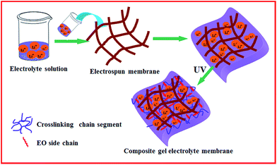
For the fabrication of CGPEs, PTA, PEGDA, and PEGMA were added to the liquid electrolytes, which were prepared by adding 1.0 M LiTFSI to BMITFSI. The CGPE were designated by the weight percentage of their components and referred to as CGPE-1 to CGPE-5 according to their different weight ratios, as shown in Table S1.† For example, the sample CGPE-3 with a weight ratio of 2/5/3 corresponds to a blend containing 20 wt% PTA, 50 wt% PEGDA, and 30 wt% PEGMA. A PVDF-HFP electrospun membrane with a thickness of about 50 μm was chosen as the polymer matrix for the CGPE. The electrospun PVDF-HFP membranes were dipped into the mixed solution. The electrospun PVDF-HFP membranes impregnated with the blended electrolytes solution were then placed under a UV lamp and the sample surface was irradiated for 20 s at the intensity of about 1000 mW cm−2. The thickness of the CGPE membrane was approximately 70 μm. A schematic describing the UV in situ polymerization procedure is provided in Fig. 1, and it shows that the cross-linking agent was incorporated into the electrospun PVDF-HFP membranes, followed by UV-irradiation.Characterization of the membranes
The surface and cross-section morphology of the electrospun and composite gel membranes were characterized via scanning electron microscopy (SEM) using an environmental scanning electron microscope (ESEM, FEI Quanta 200). Thermogravimetric analysis (TGA) was conducted using a Perkin-Elmer TGA 7 under a nitrogen flow, with the sample size of about 8–10 mg (heating rate: 10 °C min−1). To determine the crystallinity, X-ray diffraction (XRD) tests of the samples were performed using a Bruker D8 Focus X-ray diffractometer, operating at 30 kV and 20 mA with a copper target (λ = 1.54 Å) at the scanning rate of 1° min−1. The thermal analysis of the electrospun membranes was carried out via differential scanning calorimetry (DSC) using a Shimadzu DSC-60 differential scanning calorimeter at the constant heating/cooling rate of 10 °C min−1. The leakage behavior was studied via the following procedure: first, the composite gel membrane was placed between two filter papers; then, it was pressed with a standard weight and the weight of the membrane was measured every 15 min. The swelling ratio of the electrospun membrane electrolyte was determined by soaking a piece of the membrane in a mixture of liquid electrolytes. The weight of the wetted membrane was determined after soaking for 2 h and removing the excess electrolyte remaining on the surface of the membrane by gently wiping with a tissue paper. The electrolyte uptake (ε) was calculated by the following equation:| ε (%) = M − M0/M0 × 100 |
| R = MPE/MPE,saturated |
Results and discussion
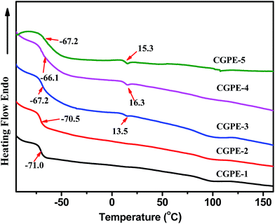
Lithium-ion batteries usually display better electrochemical performance at high temperatures due to an overall enhanced kinetics. Therefore, electrolyte materials having high electrochemical and thermal stabilities are required in some environments. TGA and DSC were used to examine the thermal stability of the composite gel polymer electrolytes. The CGPE membranes showed an 80% to 90% weight loss between 350 (onset) and 490 °C in the TGA curves after in situ cross-linking (Fig. 2). It can be seen that thermal stability was enhanced in the cross-linked polymer network with respect to that of the pure PVDF-HFP electrospun membrane. In the composite nanofibers, the cross-linked component hindered the crystallization of PVDF-HFP, which improved the thermal stability of the CGPE membranes to some extent.24 In addition, the UV cured process of cross-linking agent and PEGMA did not affect the thermal stability of the electrolytes. The good thermal stability of the CGPE membranes guarantees the safety of the battery at high temperatures. Fig. 3 summarizes the DSC results for the CGPE membranes. All CGPE membranes exhibit endothermic peaks from −65 to −71 °C, due to the glass transition phenomenon in ionic liquids. This observation confirms that ionic liquids possess a good mobility, and the crystallization of ionic liquids is reduced via cross-linking. However, the results also show that melting peaks at about 15 °C appear with the increase in the amount of PEGMA, ascribed to the linear block PEG crystallization that induces the ionic liquid crystallization. For the CGPE, the addition of PEGMA was beneficial as this component was expected to enhance the interaction with the ionic liquid electrolyte due to its comb-like PEG structure, thus retaining the ionic liquid inside the matrix.25 Additionally, because of the flexible oligomeric PEG side chains in the PPEGMA, it should be possible to use PEGMA as an electrolyte, which is beneficial for ionic transport.26 However, if PEGMA content increases such that it induces crystallization of the ionic liquid, movement will be restricted and the performance of the lithium ion battery will suffer. Therefore, a certain amount of the cross-linked component was found to be optimal, resulting in flexible and mechanically stable polymer films with good electrochemical properties, as has been discussed hereinafter.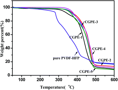 | ||
| Fig. 2 TGA curves of the CGPE membranes, obtained under a nitrogen atmosphere at the heating rate of 10 °C min−1. | ||
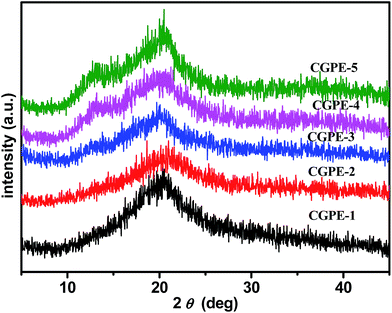
X-ray diffraction patterns of the composite gel polymer electrolytes, as shown in Fig. 4, varied with the content of the cross-linking agent. All CGPE membranes show a broader reflection at 2θ = 20.2°, which is due to the crystallinity of the PVDF-HFP electrospun membranes. The intensities of the peak weakened with the addition of the cross-linking agent as compared to that of the pure PVDF-HFP electrospun membrane.27 The interaction of the PVDF-HFP membrane with the gel polymer electrolytes may lead to a higher proportion of amorphous phase and lower crystallinity for the composite gel polymer membrane. Thus, CGPE membranes can provide more amorphous areas for Li+ ions to transfer. In addition, the cross-linked agent can be deemed to the amorphous state because there were no other characteristic peaks. Upon further increasing the amount of PEGMA, the reflection at 20.2° in the case of CGPE-5 (20/30/50) became more obvious and a diffraction hump at 2θ = 13.2° emerged, suggesting that a high content of PEGMA also enhanced the crystallinity of the CGPE to some extent, which is in good agreement with the DSC observations.
The surface and cross-section morphology of the composite gel polymer electrolyte membranes were characterized by SEM, as shown in Fig. 5. The image shows that the fibers interlaid to form a 3D network with fully interconnected interstitial pores between the fibers (Fig. 5A). These porous membranes can be evenly filled by the cross-linking agent and IL to offer connected channels for ion transport. Compared with the pure membrane, the morphology of the electrospun membrane became indistinct after UV-induced crosslinking (Fig. 5B), indicating that the cross-linking agent and IL gel electrolyte were successfully incorporated into the framework. Via cross-linking agent, some nanofibers joined at the cross-junctions or merged. This integrated structure of a CGPE membrane combining cross-linking agent with a liquid electrolyte is expected to present a desired ion conductivity with excellent mechanical properties (Table S2†). Similarly, a smooth surface with no obvious pores was observed in the cross-section image (Fig. 5C), indicating that a good morphology composed of gel polymer electrolytes was formed.
 | ||
| Fig. 5 SEM images of the polymer membranes: (A) electrospun PVDF-HFP fibres (B) CGPE-3 membrane, and (C) cross-section image of the CGPE-3 membrane. | ||
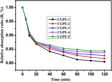
The electrolyte leakage behavior is an important feature for gel polymer electrolyte membranes based on a composite polymer matrix. Experimental results are shown in Fig. 6. The leakage behavior of the polymer membranes can be calculated by weighing the mass loss of the membranes as a function of time. It can be seen from Fig. 6 that the leakage behavior of the composite polymer membrane tends to reach an equilibrium within 2 h, and no leakage was observed thereafter. The 3D interconnected cross-linked network and hydrophilic nature of the EO chains in PEGMA help to prevent leakage of the gel electrolyte solution; thus, the composite gel polymer electrolyte membranes exhibit a high liquid retention capacity. The cross-linked polymer with EO chains shows a good compatibility with the electrolyte, which is conducive to absorb more liquid electrolytes within the polymer membrane and more electrolytes could be retained.13 Thus, the electrolyte leakage decreased with the increase in the PPEGMA content.
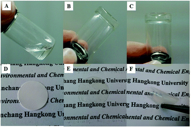
As shown in Fig. 7, a good gel was formed from an ionic liquid electrolyte with a cross-linked polymer by UV-irradiation (Fig. 7A–C), and a flexible free-standing film was obtained when the cross-linked polymer and PPEGMA were added to the electrospun nanofibers (Fig. 7E and F). A composite gel polymer electrolyte membrane was formed by UV curing of the cross-linking agent with the electrospun membrane and IL electrolytes. The interlaced electrospun nanofibers acted as a robust skeleton, conferring good mechanical properties, and the liquid gel presented the desired ion conductivity of the electrolyte. Moreover, this ensured the effective encapsulation of the IL-based gel polymer electrolyte within the cell, promoting interfacial adhesion between the electrodes and the electrolyte in lithium-ion batteries.
Fig. 8 shows the temperature-dependence of the ionic conductivity for all the CGPE membranes with 1.0 M LiTFSI IL electrolyte solutions. The introduction of the cross-linking agent has a significant effect on the ionic conductivity of CGPE membranes, and the ionic conductivity increased with increasing temperature. This is because the cross-linked polymer contributes to lock more liquid electrolytes, which favors ion transport and ionic mobility. The ionic conductivity of CGEP-1 is much lower than that of the pure electrospun PVDF-HFP IL gel electrolytes (the value is 1.5 × 10⁻³ S cm−1 at room temperature, as reported in our previous work).27 Due to the formation of a three-dimensional network by cross-linking, there was an increase in the resistance, which inhibited ion transport and led to an inevitable decrease in the ionic conductivity as the cross-linking density increased. However, the ionic conductivity of the composite gel polymer electrolyte membranes increased with the increasing PEGMA content at all temperatures. Since ion transport mainly occurs in the IL phase, the reason for the improved ionic conductivity in the CGPE membrane is related to the hydrophilicity of the PEG chains and its good liquid retention ability. The reduced ionic conductivity of the CGPE-4 and CGPE-5 membranes at a higher concentration of PEGMA was ascribed to the increased density of the three-dimensional network and the induced crystallization, as proven by the DSC and XRD results. Thus, the degree of cross-linking is a key factor for ionic conductivity. Moreover, the appropriate three-dimensional network not only favors a better liquid uptake, but also reduces leakage. The ionic conductivity of the composite gel polymer electrolytes based on some other ILs with different anions (BMITf and BMIBF4) were also investigated, and the results are shown in Fig. S1.† The polymer electrolytes were denoted as CGPE-BMIBF4 and CGPE-BMITf, with the same components as CGPE-3 (Table S3†). The results demonstrate that the composite gel polymer electrolyte based on BMIBF4 exhibited the highest value at all temperatures. This is related to the anionic structure and the molar conductivity of the three anions, which follows the order BF4− > TFSI− > Tf−.28
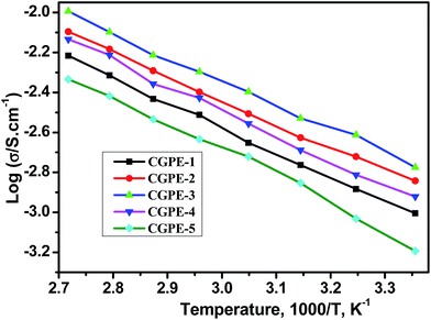 | ||
| Fig. 8 Temperature-dependence of the ionic conductivity of the CGPE membranes when immersed in 1.0 M LiTFSI + BMITFSI. | ||
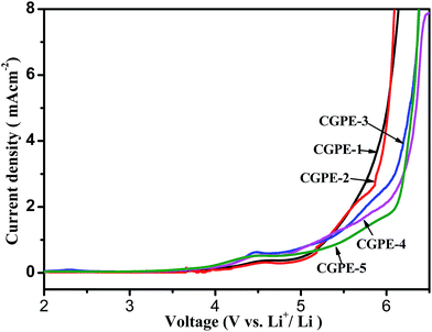
The electrochemical stability of the composite gel cross-linked polymer electrolytes encapsulated within the electrospun matrix were evaluated via linear sweep voltammetry (LSV). LSV curves of the CGPE membranes as obtained from SS|CGPE|Li scans are shown in Fig. 9. A very low background current was measured in the potential range between 2.0 and 6.5 V for different CGPE membranes. An obvious current began to flow when it reached above 5.0 V, indicating that the electrolyte began to decompose. All the composite gel polymer electrolyte membranes showed good oxidative stabilities up to 5.0 V. The weak hump between 4.3 and 4.6 V is ascribed to the oxidation of water and oxygen. Therefore, the composite gel polymer electrolyte membranes with a cross-linked structure have a suitable electrochemical stability for lithium-ion battery applications.
To demonstrate that the CGPE are suitable for application in rechargeable lithium-ion batteries, a cell was assembled for further testing. Fig. 10A presents the charge/discharge profile of the Li/CGPE/LiFePO4 cell based on the CGPE membrane at the current rate of C/10. The specific capacity of the coin cells based on different electrolyte membranes of CGPE-1, CGPE-2, CGPE-3, CGPE-4, and CGPE-5 are 139, 151, 160, 152, and 133 mA h g−1 at 0.1C, respectively. In the LiFePO4 half-cell system, it can be seen that the curve displays a plateau, which is attributed to the charge–discharge process due to the Fe2+/Fe3+ oxidation–reduction reaction. The capacitor of the cells composed with CGPE-3 possessed the highest efficiency, possibly due to the high electrolyte retention ability and good ionic conductivity of the IL membrane. CGPE-3 showed a steady cycle life with a coulombic efficiency of nearly 98% after 100 cycles, as shown in the inset of Fig. 10A. The good capacity retention after 100 cycles is due to the high ionic conductivity and stable interfacial layer in the cell. The properties of the cell with the composite gel polymer electrolyte membranes based on BMIBF4 and BMITf were also studied for comparison (Fig. S2†). Note that the cells based on the BMITFSI electrolyte consistently delivered the highest capacities. The results demonstrated that the anion structure significantly influenced the cell performance, and the hydrophilic nature of BMITFSI afforded a strong affinity interaction between the cross-linking matrix and ionic liquid. The rate capability and cycling stability of the cell based on the CGPE membrane at different current densities are shown in Fig. 10B. The discharge current rate increased from 0.1 to 2.0C and returned to 0.1C for the last 20 cycles. The CGPE battery showed a promising capacity retention with a negligible decay after 120 cycles of galvanostatic charge–discharge at various C-rates. The discharge capacity of the battery using all the electrolytes decreased as the discharge rate increased. In addition, the battery based on the CGPE-3 electrolyte outperformed the rest, having the highest specific capacity at all rates. For the cell based on the CGPE-3 membrane, the initial discharge capacity decreased from 160 to 150, 136, 122, and 91 mA h g−1 when the current rate was increased from C/10 to C/5, C/2, 1.0C, and 2.0C, respectively. The main reason for the lower capacities at higher current rates is the intrinsic properties of the gel polymer electrolytes, which were caused by polarization at higher charge–discharge rates. The discharge capacity of the battery with the CGPE-3 membrane is the highest among all the samples at all current rates; this suggests that an appropriate composite polymer network with a cross-linked CGPE membrane structure endows to lithium-ion batteries with good cycling and rate performances.
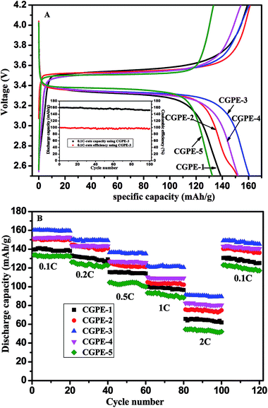 | ||
| Fig. 10 (A) Initial charge–discharge properties and cycling performance at the charge–discharge current density of 0.1C and (B) rate capability of Li/GPE/LiFePO4 cells using CGPE (25 °C 2.5–4.2 V). | ||
Conclusions
Deformable and safe composite gel polymer electrolyte (CGPE) membranes were successfully prepared for lithium-ion batteries. It was discovered that the ionic conductivity of the CGPE membranes was affected by the content of cross-linking agent and PEGMA. The DSC/TGA curves and characterization of the morphology of the electrolyte membranes showed that a reticulate polymer electrolyte film based on a PVDF-HFP electrospun matrix and with a cross-linked structure was successfully formed. It was also verified that the in situ UV-irradiation cannot compromise the beneficial characteristics of the ionic liquid electrolytes. Compared to the normal gel polymer electrolytes without a cross-linked skeleton, this type of CGPEs showed clear improvements in terms of membrane stability, liquid retention properties, and mechanical flexibility. The Li/CGPE/LiFePO4 cell with CGPE-3 exhibited a high specific capacity and superior stable cycling performance, with the specific capacities of 160, 150, 136, 122, and 91 mA h g−1 at a 0.1, 0.2, 0.5, 1.0, and 2.0C rate, respectively, and retained its properties well after 100 cycles. The anion type in the ionic liquid significantly affected the cell performance, and the CGPE-3 based on BMITFSI exhibited the best performance. These excellent results demonstrate that CGPE-3 is a very promising polymer electrolyte for high-performance lithium ion batteries.Acknowledgements
This work was supported by the National Natural Science Foundation of China (21404054), the Aeronautical Science Foundation of China (2015ZF56020), and the Science and Technology Project of Educational Department of the Jiangxi Province (DB201602034).Notes and references
- F. Croce, G. B. Appetecchi, L. Persi and B. Scrosati, Nature, 1998, 394, 456–458 CrossRef CAS.
- M. Armand and J. M. Tarascon, Nature, 2008, 451, 652–657 CrossRef CAS PubMed.
- K. Wang, S. Luo, Y. Wu, X. He, F. Zhao, J. Wang, K. Jiang and S. Fan, Adv. Funct. Mater., 2013, 23, 846–853 CrossRef CAS.
- K. H. Choi, S. J. Cho, S. H. Kim, Y. H. Kwon, J. Y. Kim and S. Y. Lee, Adv. Funct. Mater., 2014, 24, 44–52 CrossRef CAS.
- J. Li, Y. Hou, X. Gao, D. Guan, Y. Xie, J. Chen and C. Yuan, Nano Energy, 2015, 16, 10–18 CrossRef CAS.
- B. Scrosati and J. Garche, J. Power Sources, 2010, 195, 2419–2430 CrossRef CAS.
- D. Fu, B. Luan, S. Argue, M. N. Bureau and I. J. Davidson, J. Power Sources, 2012, 206, 325–333 CrossRef CAS.
- S. M. Seidel, S. Jeschke, P. Vettikuzha and H. D. Wiemhofer, Chem. Commun., 2015, 51, 12048–12051 RSC.
- P. Yang, L. Liu, L. Li, J. Hou, Y. Xu, X. Ren, M. An and N. Li, Electrochim. Acta, 2014, 115, 454–460 CrossRef CAS.
- P. Raghavan, X. Zhao, C. Shin, D. H. Baek, J. W. Choi, J. Manuel, M. Y. Heo, J. H. Ahn and C. Nah, J. Power Sources, 2010, 195, 6088–6094 CrossRef CAS.
- J. J. Xu and H. Ye, Electrochem. Commun., 2005, 7, 829–835 CrossRef CAS.
- M. Wetjen, G. T. Kim, M. Joost, M. Winter and S. Passerini, Electrochim. Acta, 2013, 87, 779–787 CrossRef CAS.
- D. F. Miranda, C. Versek, M. T. Tuominen, T. P. Russell and J. J. Watkins, Macromolecules, 2013, 46, 9313–9323 CrossRef CAS.
- Q. Lu, J. Yang, W. Lu, J. Wang and Y. Nuli, Electrochim. Acta, 2015, 152, 489–495 CrossRef CAS.
- A. Khanlari, M. S. Detamore and S. H. Gehrke, Macromolecules, 2013, 46, 9609–9617 CrossRef CAS.
- S. H. Wang, S. S. Hou, P. L. Kuo and H. Teng, ACS Appl. Mater. Interfaces, 2013, 5, 8477–8485 CAS.
- I. Osada, H. de Vries, B. Scrosati and S. Passerini, Angew. Chem., Int. Ed., 2016, 55, 500–513 CrossRef CAS PubMed.
- M. Armand, F. Endres, D. R. MacFarlane, H. Ohno and B. Scrosati, Nat. Mater., 2009, 8, 621–629 CrossRef CAS PubMed.
- N. Wongittharom, C. H. Wang, Y. C. Wang, G. T. K. Fey, H. Y. Li, T. Y. Wu, T. C. Lee and J. K. Chang, J. Power Sources, 2014, 260, 268–275 CrossRef CAS.
- J. H. Kim, S. Y. Bae, J. H. Min, S. W. Song and D. W. Kim, Electrochim. Acta, 2012, 78, 11–16 CrossRef CAS.
- P. Arora and Z. Zhang, Chem. Rev., 2004, 104, 4419–4462 CrossRef CAS PubMed.
- X. Li, G. Cheruvally, J. K. Kim, J. W. Choi, J. H. Ahn, K. W. Kim and H. J. Ahn, J. Power Sources, 2007, 167, 491–498 CrossRef CAS.
- J. K. Kim, L. Niedzicki, J. Scheers, C. R. Shin, D. H. Lim, W. Wieczorek, P. Johansson, J. H. Ahn, A. Matic and P. Jacobsson, J. Power Sources, 2013, 224, 93–98 CrossRef CAS.
- Z. Zhang, G. Sui, H. Bi and X. Yang, J. Membr. Sci., 2015, 492, 77–87 CrossRef CAS.
- C. Liao, X. G. Sun and S. Dai, Electrochim. Acta, 2013, 87, 889–894 CrossRef CAS.
- M. Patel, M. Gnanavel and A. J. Bhattacharyya, J. Mater. Chem., 2011, 21, 17419–17424 RSC.
- Y. Tong, M. Que, S. Su and L. Chen, Ionics, 2016, 22, 1311–1318 CrossRef CAS.
- H. Tokuda, K. Hayamizu, K. Ishii, M. A. B. H. Susan and M. Watanabe, J. Phys. Chem. B, 2004, 108, 16593–16600 CrossRef CAS.
Footnote |
| † Electronic supplementary information (ESI) available. See DOI: 10.1039/c7ra00112f |
| This journal is © The Royal Society of Chemistry 2017 |

