DOI:
10.1039/C7RA00050B
(Paper)
RSC Adv., 2017,
7, 10668-10674
Facile stir-dried preparation of g-C3N4/TiO2 homogeneous composites with enhanced photocatalytic activity
Received
3rd January 2017
, Accepted 3rd February 2017
First published on 8th February 2017
Abstract
g-C3N4/TiO2 composites with homogeneous well-combined structures were prepared by a simple stir-dried method, using dicyandiamide (DICY) and tetrabutyl orthotitanate (TBOT) as the precursors, followed by high-temperature calcination. Various characterization techniques including XRD, FTIR, nitrogen adsorption–desorption, SEM and XPS confirm the formation of an interconnected structure between g-C3N4 and TiO2 in the composites. g-C3N4/TiO2 composites exhibit much higher photocatalytic activity than that of pure g-C3N4 and TiO2 in the degradation of methylene blue under visible light. In particular, the CT-5 composite prepared with DICY/TBOT at a mass ratio of 5![[thin space (1/6-em)]](https://www.rsc.org/images/entities/char_2009.gif) :1, exhibited a photodegradation activity that is about 3.8 times that of TiO2 and 2.9 times that of pure g-C3N4. The homogeneous g-C3N4/TiO2 composite CT-5 can be repetitively used without significant loss of activity. The strong synergistic effect between g-C3N4 and TiO2 achieved by this preparation method greatly improves the separation efficiency of photo-generated electrons and holes, thus offering enhanced photocatalytic performances.
:1, exhibited a photodegradation activity that is about 3.8 times that of TiO2 and 2.9 times that of pure g-C3N4. The homogeneous g-C3N4/TiO2 composite CT-5 can be repetitively used without significant loss of activity. The strong synergistic effect between g-C3N4 and TiO2 achieved by this preparation method greatly improves the separation efficiency of photo-generated electrons and holes, thus offering enhanced photocatalytic performances.
1. Introduction
Titania has been the most popular photocatalyst in photocatalysis since 1972 when Fujishima and Honda discovered the TiO2 photoelectrode.1 It has been widely used in generating H2 from water and in controlling water pollution discharged from industry, such as the reduction of heavy metal ions2,3 and the degradation of organic dyes.4–6 However, the biggest drawback of TiO2 is its large band gap (3.2 and 3.0 eV for anatase and rutile, respectively) and thus can only harvest UV light, which makes up merely 3–5% of solar light, thereby restricting practical applications of titania.7 Therefore, much effort has been devoted to make TiO2 absorb visible light. In recent years, various methods for TiO2 modification have been attempted, including doping non-metal elements6,8–10 and constructing composites with other semiconductors.11–13 Besides these modifications, metal deposition14–16 has also been extensively explored, and plasmonic metals, such as Au, Ag, and Cu which absorb visible light owing to their surface plasmon resonance effect, are employed as a sink of photo-induced electrons to enhance charge separation efficiency.17,18 Though progress has been made, the cost of the metals is expensive and their enhancing efficiency is still in question.
Polymeric graphitic carbon nitride (g-C3N4) is the most stable material of all the carbon nitride allotropes under ambient conditions.19,20 Besides, unlike the photocatalysts of sulphide and oxynitride semiconductor, the g-C3N4 is stable under light irradiation in water solution as well as strong acid or base solutions.21,22 Furthermore, its band gap energy is only 2.58–2.89 eV.23 The above-mentioned advantages make g-C3N4 a promising photocatalyst under visible light in various solutions. Some reports have focused on the applications of g-C3N4 in water splitting24–26 and organic pollutant degradation;27,28 Nonetheless, the high recombination rate of photo-generated electron–hole pairs results in a low photocatalytic activity of g-C3N4. To overcome this problem, coupling with TiO2 is a feasible method because the interfacial connection between g-C3N4 and TiO2 can make the electrons transfer easily from g-C3N4 (CB) to TiO2 (CB).29 Sridharan et al. prepared g-C3N4/TiO2 through a thermal transformation method, and the improved photocatalytic activity was attributed to the formation of a synergistic heterojunction and the combination of both g-C3N4 and doped TiO2 to absorb visible light more effectively.30 A hybrid g-C3N4/TiO2 has been synthesized by a ball milling method, and the enhanced photocatalytic activities were due to the hybrid structure.31 The growth of g-C3N4 on mesoporous TiO2 spheres with well-controlled structures has been achieved by melt-infiltrating dicyandiamide, and the separation efficiency between photo-generated electrons and holes was enhanced significantly.32 Ma and co-workers prepared g-C3N4/TiO2 via a simple one-step calcination method using commercial P25 and melamine as the precursors, and they found the interfacial interaction of g-C3N4 and TiO2 was crucial to the efficiency of NO photocatalytic oxidation.29 Although the prepared g-C3N4/TiO2 composites have performed good photocatalytic activities, there is still a challenge to readily synthesize such a structure with well interconnected g-C3N4 and TiO2 to reduce the migration barrier of charge carriers.
In this work, g-C3N4/TiO2 homogeneous composites have been synthesized by a simple and effective stir-dried method. The TiO2 precursor tetrabutyl orthotitanate (TBOT) and the g-C3N4 precursor dicyandiamide (DICY) were dissolved in ethanol and experienced the stir-drying to form a well-blended mixture. Thus-formed g-C3N4/TiO2 composites were obtained by calcining the mixture in a muffle furnace. Moreover, g-C3N4/TiO2 composites with different DICY/TBOT mass ratios were studied systematically, and the resulting composites exhibited higher photoactivity than that of the pure g-C3N4 and TiO2 for the degradation of methylene blue under visible light.
2. Materials and methods
2.1 Chemicals
Dicyandiamide (DICY, 99%) was obtained from Adamas, China. Tetrabutyl orthotitanate (TBOT) was purchased from Shanghai Lingfeng Chemical, China. Methylene Blue (MB) was obtained from Acros, New Jersey, USA. Anhydrous ethanol was purchased from Sinopharm Chemical, China. All chemicals were used as received without further treatment.
2.2 Preparation of homogeneous g-C3N4/TiO2
A series of g-C3N4/TiO2 mixtures were prepared. In a typical synthesis, 0.2–2 g of TBOT was dissolved in 50 mL of anhydrous ethanol and stirred for 10 min. 2 g of DICY was added into the TBOT solution and ultrasonicated for 10 min, and then stirred for another 2 h to ensure their thorough dissolving and mixing. The mixture solution was undergone alcoholysis and stir-dried by evaporation at 65 °C oil bath. The resulting slurry was further dried at 60 °C overnight. The mixture solids were then ground and calcined at 500 °C for 1 h. g-C3N4/TiO2 composites were obtained and marked as CT-0, CT-1, CT-5 and CT-10 when DICY/TBOT mass ratios were of 0:1, 1:1, 5:1 and 10:1, respectively. For comparison, pure g-C3N4 was obtained by calcining 2 g of DICY under the same calcination condition.
2.3 Characterizations
The phase structure of the TiO2-based photocatalysts were examined by X-ray diffraction (XRD) using Rigaku MiniFlex II with Cu Kα radiation (λ = 0.1542 nm) at 40 kV. Nitrogen adsorption–desorption analysis was conducted using a Micromeritics ASAP 2020 at 77 K. Each sample was degassed at 120 °C for 120 min previous to analysis. The specific surface areas (SBET) were calculated by the Brunauer–Emmett–Teller (BET) method. Fourier transform infrared spectra (FTIR) was recorded by a FTIR spectrophotometer (Thermo Electron Nicolet-360, USA) using the KBr wafer technique. The morphology of the samples was observed by scanning electron microscopy (SEM) utilizing a MAGELLAN 400 (FEI, USA) with an operating voltage of 5 kV, and elemental mapping images were obtained by using Energy-Dispersive X-ray Spectroscopy (EDX) on MAGELLAN 400 microscope. X-ray photoelectron spectroscopy (XPS) (AXIS UltraDLD, Japan) was employed to determine surface electronic states. All the binding energies were referenced to the C 1s peak at 284.8 eV of the surface adventitious carbon. The UV-Vis diffuse reflectance spectra (DRS) of the samples over a range of 200–800 nm were recorded by UV-2600 (Shimadzu, Japan) spectrophotometer with a BaSO4 reference. Room temperature photoluminescence (PL) spectra was recorded on a spectrofluorometer (FluoroMax-4, HORIBA Jobin Yvon) using a Xe lamp as the excitation source.
2.4 Photocatalytic activity test
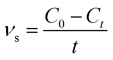
Methylene blue (MB) was used as a probe dye to evaluate the photocatalytic activity of the g-C3N4/TiO2 composites under a 300 W xenon lamp (CEL-HXF300, light intensity: 83 mW cm−2). To analyze the photocatalytic activity of g-C3N4/TiO2 composites under visible light, a UV cut-off filter (λ > 420 nm) was used. Typically, 40 mg of the as-prepared photocatalyst was dispersed in a 40 mL of MB aqueous solution (10 mg L−1) under constant stirring. Prior to illumination, the solution was kept in dark for 60 min and stirred to reach an adsorption–desorption equilibrium. At given intervals, the supernatant liquid was obtained by filtration with 0.22 μm filter and examined using a UNICO WFZ UV-2802s spectrophotometer at the characteristic wavelength of 664 nm. To evaluate the stability of photocatalyst, the photocatalyst was collected by centrifugation, washing and drying after the photocatalytic reaction for the recycling test. The degradation rates were calculated according to the following equation:| |
 | (1) |
where νs (mg L−1 min−1) is the degradation rate of samples to MB. C0 (mg L−1) and Ct (mg L−1) stand for the concentrations of dye at initial and time t (min).
3. Results and discussion
3.1 Preparation of g-C3N4/TiO2 composite
XRD patterns of g-C3N4, CT-10, CT-5, CT-1, CT-0 are shown in Fig. 1. The diffraction peak of pure g-C3N4 at 2θ 27.4° represents the conjugated aromatic system, which is indexed to (002) graphitic material.33 An obvious g-C3N4 characteristic peak is shown in CT-10. A relatively weak peak of g-C3N4 is observed in CT-5 (inset in Fig. 1), showing that the presence of g-C3N4. However, no obvious diffraction peak of g-C3N4 is found in CT-1, probably due to the very small amount of DICY used. CT-0 shows several characteristic peaks at 2θ 25.3°, 37.8°, 48.0°, 53.9° and 55.0°, which are attributed to (101), (004), (200), (105) and (211) crystal planes of anatase TiO2, respectively.34,35 For CT-1, CT-5 and CT-10, TiO2 characteristic peaks are found in all samples. It is worthy to note the diffraction peak of the (101) face shifts toward lower angles (25.1°) for sample CT-5 and CT-10, and the d-spacing of (101) face changes from 0.3520 to 0.3548 nm according to the Bragg equation, probably because some N ions are doped into TiO2 crystal.36
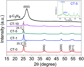 |
| | Fig. 1 XRD patterns of g-C3N4, CT-10, CT-5, CT-1, CT-0 and magnified CT-5 (inset). | |
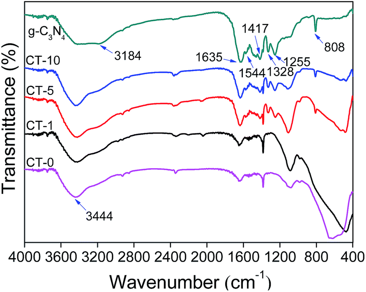
FTIR spectra were recorded to show chemical structures of g-C3N4, CT-10, CT-5, CT-1 and CT-0. As presented in Fig. 2, characteristic peaks of g-C3N4 and pure anatase TiO2 (CT-0) are consistent to those in literature.37–39 For g-C3N4, several adsorption peaks in the region of 1200–1650 cm−1 are attributed to the typical stretching modes of g-C3N4 heterocycles. Among them, the adsorption peaks at 1255, 1328, 1417, 1544 cm−1 are assigned to aromatic C–N stretching, and the peaks at 1635 cm−1 are ascribed to C–N stretching.40,41 In addition, the peak at 808 cm−1 is ascribed to characteristic breathing mode of triazine unites.42 A wide adsorption region of 3000–3600 cm−1 (e.g. 3184, 3444 cm−1) are assigned to N–H stretching vibration of remainder NH2 group attached to the sp2 hybridized carbon and O–H stretching concerned with the adsorbed water.43,44 In the spectrum of CT-0, a wide band from 400 to 800 cm−1 is ascribed to Ti–O–Ti stretching vibration mode.45,46 All characteristic adsorption peaks of g-C3N4 and anatase TiO2 appear obviously in CT-10 and CT-5 spectra, demonstrating a successful combination of g-C3N4 and TiO2.47 As expected, the spectrum of CT-1 is very similar to that of CT-0 that confirms the low amount of g-C3N4 in CT-1.
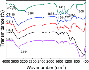 |
| | Fig. 2 FTIR spectra of g-C3N4, CT-10, CT-5, CT-1 and CT-0. | |
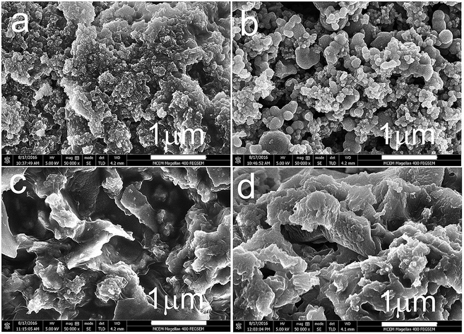
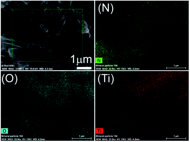
The morphologies of pristine g-C3N4, pure anatase TiO2 and g-C3N4/TiO2 composites were investigated, and SEM images of g-C3N4, CT-0, CT-5 and CT-10 are shown in Fig. 3. Pristine g-C3N4 presents a bulk structure composed of sub-micrometer particles, and pure anatase TiO2 CT-0 shows spherical-like particles with sizes of 20–200 nm. CT-5 and CT-10 also show a bulk structure, whereas no spherical-like particles were observed. Such structures could partially confirm that TiO2 and g-C3N4 are interconnected. In order to further prove the homogenous structure of g-C3N4/TiO2 composites, CT-5 was selected to conduct the EDX mapping with the results give in Fig. 4, which shows that the sample CT-5 contains elements of N, O and Ti. It is clearly shown that element N, O and Ti are well dispersed in the sample, indicating g-C3N4 and TiO2 form a homogeneous structure. The homogeneous structure is beneficial to efficient charge carrier separation in photocatalysis.
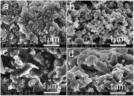 |
| | Fig. 3 SEM images of the g-C3N4 (a), CT-0 (b), CT-5 (c) and CT-10 (d). | |
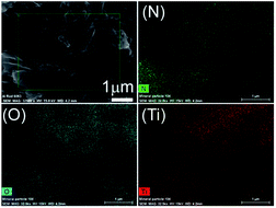 |
| | Fig. 4 EDX mapping of N, O and Ti element of the CT-5. | |
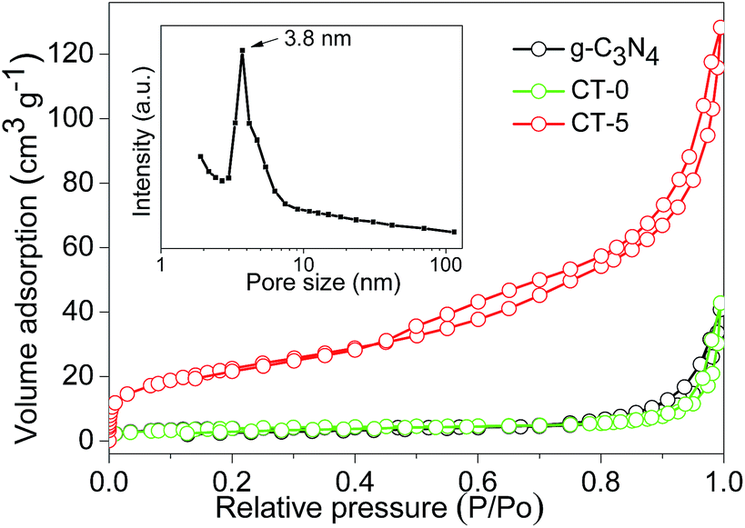
BET surface areas and pore volumes of the samples were tested by nitrogen adsorption–desorption, and the nitrogen adsorption–desorption isotherms of g-C3N4, CT-0 and CT-5 are displayed in Fig. 5. The amount of nitrogen adsorption is very low for g-C3N4 and CT-0. g-C3N4 has a BET surface area of 14 m2 g−1 that is similar to the previous reports,48,49 indicating the formation of bulk structure of g-C3N4. Pure anatase TiO2 CT-0 also shows a low BET surface area of 14 m2 g−1. By incorporation of g-C3N4, CT-1 has a BET surface area of 29 m2 g−1. For CT-5, its nitrogen adsorption capacity has a dramatic increase, and its BET surface area increases to 78 m2 g−1. Pore size distribution indicates CT-5 has a peak pore size of 3.8 nm (inset in Fig. 5), which should arise from the intraparticle voids. The pore volume of CT-5 increases to 0.147 cm3 g−1 that is higher than those of g-C3N4 and CT-0 (0.026–0.034 cm3 g−1). It is believed that the suitable amount of g-C3N4 favors a good dispersion of g-C3N4 and TiO2 to form a homogeneous structure. However, excess amount of g-C3N4 in CT-10 tends to self-aggregation, leading to a low surface area (49 m2 g−1) and a low pore volume (0.098 cm3 g−1). A high surface area and pore volume benefit the enhancement of photocatalytic performance.
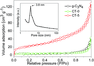 |
| | Fig. 5 N2 adsorption–desorption isotherms of g-C3N4, CT-0 and CT-5, and pore size distribution of CT-5 (inset). | |
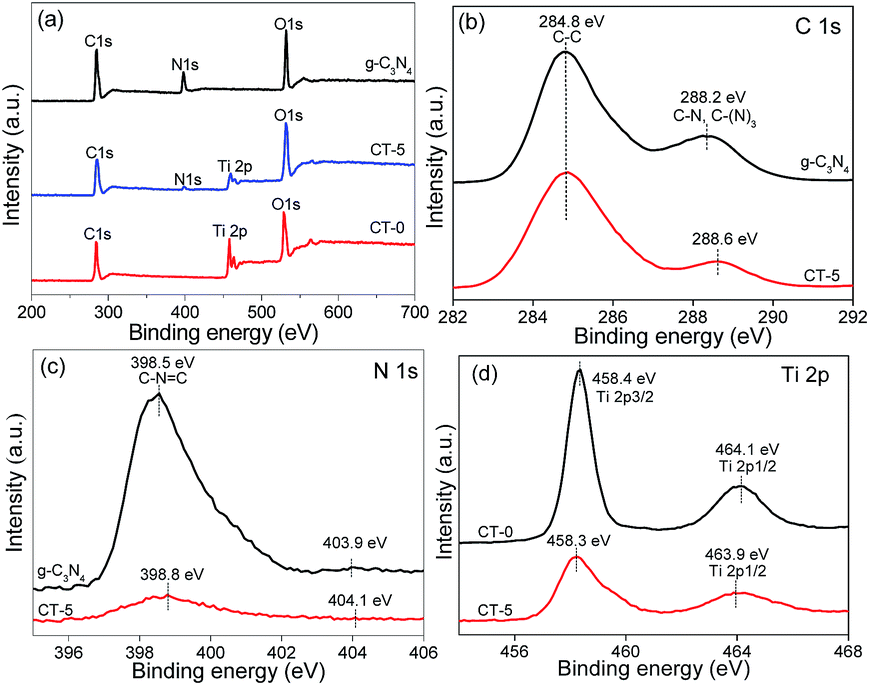
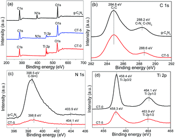
XPS analyses were carried out to investigate the surface chemical compositions of the samples and the oxidation state of key elements of C, N, and Ti. XPS survey spectra of g-C3N4, CT-0 and CT-5 are given in Fig. 6a, showing the element C, N, Ti and O are observed. The common C 1s signal about 284.8 eV is set for calibration. N and Ti elements are obviously observed in CT-5, implying the presence of g-C3N4 and TiO2 in the composite, which is in accordance with the results demonstrated by the XRD patterns and the FTIR spectra. Fig. 6b–d show the high-resolution XPS spectra of C 1s, N 1s and Ti 2p. In the C 1s XPS spectrum of g-C3N4, there are two peaks (Fig. 6b). The peak at about 284.8 eV is ascribed to the adventitious carbon, and the peak at about 288.2 eV is ascribed to C–N or C–(N)3 groups.50 For the CT-5 sample, the C 1s peaks are similar to those of g-C3N4. However, the peaks of C–N or C–(N)3 groups shift 0.4 eV towards the higher binding energy, probably due to the hybridization of g-C3N4 and TiO2. The N 1s spectrum of g-C3N4 and CT-5 are shown in Fig. 6c and two peaks can be seen. Peaks at about 398.5 and 403.9 eV are attributed to the C–N![[double bond, length as m-dash]](https://www.rsc.org/images/entities/char_e001.gif) C groups and charging effects.51,52 By comparison, the two peaks of CT-5 in the N 1s spectrum shift 0.3 and 0.2, respectively, which is due to the chemical environment change arising from the close interaction between g-C3N4 and TiO2.53 The Ti 2p spectra of CT-0 and CT-5 are shown in Fig. 6d, two peaks at ca. 458.4 and 464.1 eV for CT-0 sample are assigned to Ti 2p3/2 and Ti 2p1/2, suggesting the existence of Ti(IV).54 For the CT-5 sample, the binding energy of Ti 2p3/2 is the same as that of CT-0, and the slight shift for binding energy of Ti 2p1/2 is ascribed to the interaction between g-C3N4 and TiO2.
C groups and charging effects.51,52 By comparison, the two peaks of CT-5 in the N 1s spectrum shift 0.3 and 0.2, respectively, which is due to the chemical environment change arising from the close interaction between g-C3N4 and TiO2.53 The Ti 2p spectra of CT-0 and CT-5 are shown in Fig. 6d, two peaks at ca. 458.4 and 464.1 eV for CT-0 sample are assigned to Ti 2p3/2 and Ti 2p1/2, suggesting the existence of Ti(IV).54 For the CT-5 sample, the binding energy of Ti 2p3/2 is the same as that of CT-0, and the slight shift for binding energy of Ti 2p1/2 is ascribed to the interaction between g-C3N4 and TiO2.
 |
| | Fig. 6 XPS spectra of g-C3N4, CT-5 and CT-0 (a), high resolution XPS spectra of C 1s (b), N 1s (c) and Ti 2p (d). | |
3.2 Photocatalytic performance
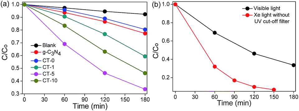
The photocatalytic performances of g-C3N4, CT-0, CT-1, CT-5 and CT-10 were investigated by the degradation of MB. CT-5 exhibits the best photocatalytic performance under visible light irradiation as compared to other photocatalysts (Fig. 7a), about 3.8 times higher as to CT-0 and 2.9 times to the pure g-C3N4. The photoactivity of CT-10 is better than that of CT-1. These results demonstrate that g-C3N4/TiO2 composites (CT-1, CT-5 and CT-10) offer much better degradation performance than that of pure g-C3N4 and pure anatase TiO2 CT-0. Pure g-C3N4 shows a little higher photocatalytic activity than CT-0, owing to its small band gap, but the high recombination rate of photo electrons and holes limits its photocatalytic activity. The above results demonstrate that the combination of g-C3N4 and TiO2 not only enormously improves light harvest, but also increases the survival time of photo-induced electrons. The photodegradation efficiency of CT-5 under Xe light without UV cut-off filter is shown in Fig. 7b, in which CT-5 could degrade 94% of MB in 2.5 h, but only 67% of MB could be decomposed under visible light irradiation in 3 h, demonstrating the generality of the synthetic effect of g-C3N4/TiO2 composites.
 |
| | Fig. 7 Photodegradation of MB using different photocatalysts under visible light (λ > 420 nm, light intensity 83 mW cm−2) (a) and photodegradation of MB over CT-5 under visible light (λ > 420 nm, light intensity 83 mW cm−2) and Xe light without UV cut-off filter (light intensity 83 mW cm−2) (b). | |
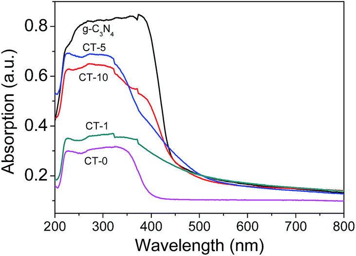
In Fig. 8, the UV-Vis spectra of g-C3N4 and g-C3N4/TiO2 composites show that the main absorption edge of the pure g-C3N4 occurs at ca. 450 nm, comparing with CT-0 in the wavelength of 400–800 nm. The absorption threshold values of the g-C3N4/TiO2 composites are extended up to the visible light region (500 nm) obviously, which confirms that more visible light can be harvested by g-C3N4/TiO2 composites.
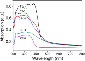 |
| | Fig. 8 UV-Vis diffuse reflection spectra of various samples: g-C3N4, CT-0, CT-1, CT-5 and CT-10. | |
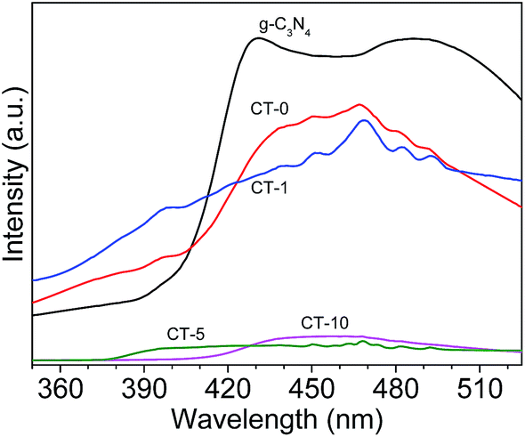
Photoluminescence (PL) spectra of the photocatalysts is shown in Fig. 9. The PL intensity of CT-5 and CT-10 are significantly reduced in comparison with pure g-C3N4,48 indicating that the electron–hole recombination on the surface of these photocatalysts is largely inhibited, to generate more photo-induced electrons and holes to participate in the photocatalytic reaction. At the same time, the survival time of photoelectrons is increased greatly, which is crucial to the photocatalytic efficiency. This is because the interfacial interaction between g-C3N4 and TiO2 can prevent the recombination of photo-generated charge effectively. The strong intensity of CT-1 is probably due to small amount of g-C3N4 in TiO2, leading to poor interfacial interaction between g-C3N4 and TiO2. Therefore, the above results, including BET surface areas, UV-Vis diffuse reflection spectra and PL spectra, are consistent to their photodegradation performance of MB.
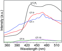 |
| | Fig. 9 PL spectra of various photocatalysts: g-C3N4, CT-0, CT-1, CT-5 and CT-10. | |
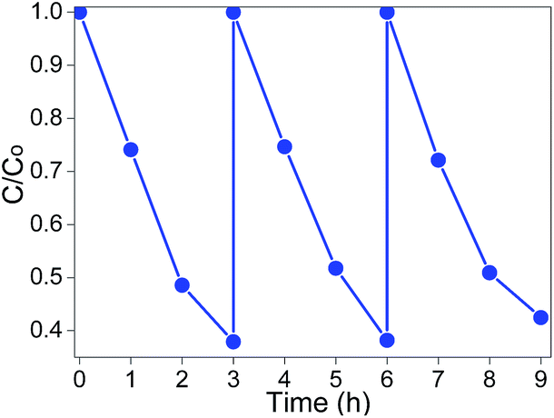
To evaluate the reusability of CT-5, the experiments were carried out on MB degradation under visible light irradiation for three times at the same conditions. The photocatalysts were recycled by centrifugation, washed with water three times and then dried. To make sure the amount of recycled catalysts was equal to that of the first-time use, several batches of reactions were carried out under equal conditions and then combined the recycled photocatalysts together. The experimental results are shown in Fig. 10, no significant decrease of activity is observed. The slight decrease should relate to the intermediates that were strongly adsorbed on the surface of the as-prepared photocatalysts, which might decline the electron transfer velocity and the adsorption capacity.55 The reusability test indicates that CT-5 has good stability in MB photodegradation under visible light irradiation.
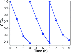 |
| | Fig. 10 Recycling test of CT-5 on photodegradation of MB (λ > 420 nm, light intensity: 83 mW cm−2). | |
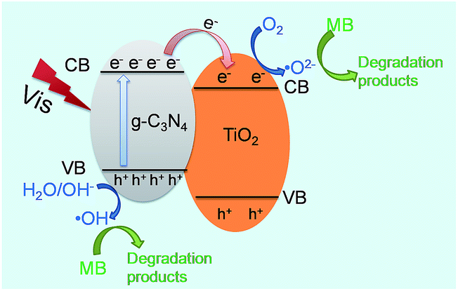
3.3 Photocatalytic mechanism of homogeneous g-C3N4/TiO2
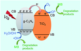
The above-mentioned results have confirmed that g-C3N4/TiO2 composite CT-5 exhibits much better photocatalytic efficiency than the pure g-C3N4 and TiO2 (CT-0). The better photocatalytic performance is mainly associated with two factors: (1) the capacity of harvesting light and (2) the separation efficiency of the photoelectrons and holes. For the first factor of light absorption, TiO2 has little adsorption of visible light; on the contrary, g-C3N4 shows a wide adsorption edge (Fig. 8). Therefore, the composite CT-5 could harvest the visible light greatly since the two substances combined together. For the second factor of charger separation, as shown in Scheme 1, when the visible light irradiates, photo-generated electrons (e−) transfer from the valence band (VB) to the conduction band (CB) of g-C3N4, leaving the holes (h+) in the VB. The different energy levels of g-C3N4 and TiO2 drive the electrons transfer from the CB of g-C3N4 to that of TiO2, thus increasing the survival time of the electrons and separating electrons and holes effectively. The homogeneously interconnected interfacial structure between g-C3N4 and TiO2 provides a closely-matched path for the free transfer of electrons, compared with the physical mixture of g-C3N4 and TiO2.32 The discussions above are called the synergistic effects between g-C3N4 and TiO2. The electrons accumulated in the CB of TiO2 are believed to reduce the oxygen (O2) to active oxygen radicals (˙O2−), and the electron-deficient holes in the VB of g-C3N4 can oxidize the hydroxyl (OH−) to hydroxyl radicals (˙OH). Both ˙O2− and ˙OH are capable to decompose MB effectively.32
 |
| | Scheme 1 Proposed mechanism of charge transfer at the interface between g-C3N4 and TiO2. | |
4. Conclusions
Facile preparation of g-C3N4/TiO2 homogeneous composites with well-combined structures has been achieved by stir-dried evaporation and high temperature calcination. The resulting g-C3N4/TiO2 composites exhibited much higher photocatalytic activity than that of pure g-C3N4 and TiO2 in the degradation of methylene blue under visible light due to the strong synergistic effect between g-C3N4 and TiO2. The CT-5 composite performed the best photocatalytic activity which was nearly 3.8 times to the TiO2 and 2.9 times compared to the pure g-C3N4. In addition, the CT-5 composite showed outstanding photocatalytic activity under Xe light, good stability and recyclability. Overall, this work provides a simple and effective path to prepare photocatalysts with fine hybrid structures and may inspire peers to design novel photocatalytic nanomaterials to enhance the efficiency of solar energy utilization for such as environmental remediation and clean chemicals synthesis.
Acknowledgements
The authors are grateful for the financial support of Natural Science Key Project of the Jiangsu Higher Education Institutions (15KJA220001), Jiangsu Specially-Appointed Professor Program and Priority Academic Program Development of Jiangsu Higher Education Institutions (PAPD).
References
- A. Fujishima and K. Honda, Nature, 1972, 238, 37–38 CrossRef CAS PubMed.
- L. B. Khalil, M. W. Rophael and W. E. Mourad, Appl. Catal., B, 2002, 36, 125–130 CrossRef CAS.
- H. Kyung, J. Lee and W. Y. Choi, Environ. Sci. Technol., 2005, 39, 2376–2382 CrossRef CAS PubMed.
- V. Vaiano, G. Iervolino, D. Sannino, J. J. Murcia, M. C. Hidalgo, P. Ciambelli and J. A. Navio, Appl. Catal., B, 2016, 188, 134–146 CrossRef CAS.
- V. Vaiano, O. Sacco, D. Sannino and P. Ciambelli, Appl. Catal., B, 2015, 170, 153–161 CrossRef.
- H. Li, Y. Hao, H. Lu, L. Liang, Y. Wang, J. Qiu, X. Shi, Y. Wang and J. Yao, Appl. Surf. Sci., 2015, 344, 112–118 CrossRef CAS.
- M. K. Seery, R. George, P. Floris and S. C. Pillai, J. Photochem. Photobiol., A, 2007, 189, 258–263 CrossRef CAS.
- J. Wang, F. Cao, Z. Bian, M. K. Leung and H. Li, Nanoscale, 2014, 6, 897–902 RSC.
- H. Lu, B. Zhao, R. Pan, J. Yao, J. Qiu, L. Luo and Y. Liu, RSC Adv., 2014, 4, 1128–1132 RSC.
- J. Du, X. Li, K. Li, X. Gu, W. Qi and K. Zhang, J. Alloys Compd., 2016, 687, 893–897 CrossRef CAS.
- K. Sridharan, E. Jang and T. J. Park, Appl. Catal., B, 2013, 142, 718–728 CrossRef.
- L. Gu, J. Wang, Z. Zou and X. Han, J. Hazard. Mater., 2014, 268, 216–223 CrossRef CAS PubMed.
- X. Sun, C. Li, L. Ruan, Z. Peng, J. Zhang, J. Zhao and Y. Li, J. Alloys Compd., 2014, 585, 800–804 CrossRef CAS.
- J. Yu, J. Xiong, B. Cheng and S. Liu, Appl. Catal., B, 2005, 60, 211–221 CrossRef CAS.
- G. Liu, Y. Zhao, C. Sun, F. Li, G. Q. Lu and H. M. Cheng, Angew. Chem., Int. Ed., 2008, 47, 4516–4520 CrossRef CAS PubMed.
- P. P. Sun, L. Liu, S. C. Cui and J. G. Liu, Catal. Lett., 2014, 144, 2107–2113 CrossRef CAS.
- Z. Bian, T. Tachikawa, P. Zhang, M. Fujitsuka and T. Majima, J. Am. Chem. Soc., 2013, 136, 458–465 CrossRef PubMed.
- W. Hou, Z. Liu, P. Pavaskar, W. H. Hung and S. B. Cronin, J. Catal., 2011, 277, 149–153 CrossRef CAS.
- Y. Gao, X. Chen, J. Zhang and N. Yan, ChemPlusChem, 2015, 80, 1556–1564 CrossRef CAS.
- X. Chen, H. Yang and N. Yan, Chem.–Eur. J., 2016, 22, 13402–13421 CrossRef CAS PubMed.
- A. Thomas, A. Fischer, F. Goettmann, M. Antonietti, J.-O. Müller, R. Schlögl and J. M. Carlsson, J. Mater. Chem., 2008, 18, 4893–4908 RSC.
- J. Hu, W. Cheng, S. Huang, D. Wu and Z. Xie, Appl. Phys. Lett., 2006, 89, 1117 Search PubMed.
- S. Cao, J. Low, J. Yu and M. Jaroniec, Adv. Mater., 2015, 27, 2150–2176 CrossRef CAS PubMed.
- X. Wang, K. Maeda, X. Chen, K. Takanabe, K. Domen, Y. Hou, X. Fu and M. Antonietti, J. Am. Chem. Soc., 2009, 131, 1680–1681 CrossRef CAS PubMed.
- Z. Ding, X. Chen, M. Antonietti and X. Wang, ChemSusChem, 2011, 4, 274–281 CAS.
- K. Takanabe, K. Kamata, X. Wang, M. Antonietti, J. Kubota and K. Domen, Phys. Chem. Chem. Phys., 2010, 12, 13020–13025 RSC.
- S. Yan, Z. Li and Z. Zou, Langmuir, 2010, 26, 3894–3901 CrossRef CAS PubMed.
- S. Yan, S. Lv, Z. Li and Z. Zou, Dalton Trans., 2010, 39, 1488–1491 RSC.
- J. Z. Ma, C. X. Wang and H. He, Appl. Catal., B, 2016, 184, 28–34 CrossRef CAS.
- K. Sridharan, E. Jang and T. J. Park, Appl. Catal., B, 2013, 142, 718–728 CrossRef.
- J. Zhou, M. Zhang and Y. Zhu, Phys. Chem. Chem. Phys., 2015, 17, 3647–3652 RSC.
- X. Chen, J. Wei, R. Hou, Y. Liang, Z. Xie, Y. Zhu, X. Zhang and H. Wang, Appl. Catal., B, 2016, 188, 342–350 CrossRef CAS.
- L. Ge, C. C. Han, J. Liu and Y. F. Li, Appl. Catal., A, 2011, 409, 215–222 CrossRef.
- M. Shen, Z. Yan, L. Yang, P. Du, J. Zhang and B. Xiang, Chem. Commun., 2014, 50, 15447–15449 RSC.
- T. C. An, J. Y. Chen, X. Nie, G. Y. Li, H. M. Zhang, X. L. Liu and H. J. Zhao, ACS Appl. Mater. Interfaces, 2012, 4, 5988–5996 CAS.
- Y. Huo, Y. Jin, J. Zhu and H. Li, Appl. Catal., B, 2009, 89, 543–550 CrossRef CAS.
- J. Yu, S. Wang, J. Low and W. Xiao, Phys. Chem. Chem. Phys., 2013, 15, 16883–16890 RSC.
- J. Lei, Y. Chen, F. Shen, L. Wang, Y. Liu and J. Zhang, J. Alloys Compd., 2015, 631, 328–334 CrossRef CAS.
- X. Song, Y. Hu, M. Zheng and C. Wei, Appl. Catal., B, 2016, 182, 587–597 CrossRef CAS.
- J.-X. Sun, Y.-P. Yuan, L.-G. Qiu, X. Jiang, A.-J. Xie, Y.-H. Shen and J.-F. Zhu, Dalton Trans., 2012, 41, 6756–6763 RSC.
- S.-W. Bian, Z. Ma and W.-G. Song, J. Phys. Chem. C, 2009, 113, 8668–8672 CAS.
- Y. Wang, R. Shi, J. Lin and Y. Zhu, Energy Environ. Sci., 2011, 4, 2922–2929 CAS.
- C. Miranda, H. Mansilla, J. Yáñez, S. Obregón and G. Colón, J. Photochem. Photobiol., A, 2013, 253, 16–21 CrossRef CAS.
- G. Zhang, J. Zhang, M. Zhang and X. Wang, J. Mater. Chem., 2012, 22, 8083–8091 RSC.
- J.-G. Yu, H.-G. Yu, B. Cheng, X.-J. Zhao, J. C. Yu and W.-K. Ho, J. Phys. Chem. B, 2003, 107, 13871–13879 CrossRef CAS.
- J. F. Yao and H. T. Wang, Ind. Eng. Chem. Res., 2007, 46, 6264–6268 CrossRef CAS.
- H. Yan and H. Yang, J. Alloys Compd., 2011, 509, L26–L29 CrossRef CAS.
- X.-j. Wang, W.-y. Yang, F.-t. Li, Y.-b. Xue, R.-h. Liu and Y.-j. Hao, Ind. Eng. Chem. Res., 2013, 52, 17140–17150 CrossRef CAS.
- Y. Wu, L. Tao, J. Zhao, X. Yue, W. Deng, Y. Li and C. Wang, Res. Chem. Intermed., 2016, 42, 3609–3624 CrossRef CAS.
- Z. H. Sheng, L. Shao, J. J. Chen, W. J. Bao, F. B. Wang and X. H. Xia, ACS Nano, 2011, 5, 4350–4358 CrossRef CAS PubMed.
- S. Zhou, Y. Liu, J. M. Li, Y. J. Wang, G. Y. Jiang, Z. Zhao, D. X. Wang, A. J. Duan, J. Liu and Y. C. Wei, Appl. Catal., B, 2014, 158, 20–29 CrossRef.
- Y. F. Chen, W. X. Huang, D. L. He, S. T. Yue and H. Huang, ACS Appl. Mater. Interfaces, 2014, 6, 14405–14414 CAS.
- H. P. Li, J. Y. Liu, W. G. Hou, N. Du, R. J. Zhang and X. T. Tao, Appl. Catal., B, 2014, 160, 89–97 CrossRef.
- M. Kong, Y. Z. Li, X. Chen, T. T. Tian, P. F. Fang, F. Zheng and X. J. Zhao, J. Am. Chem. Soc., 2011, 133, 16414–16417 CrossRef CAS PubMed.
- S. Z. Liu, H. Q. Sun, A. Suvorova and S. B. Wang, Chem. Eng. J., 2013, 229, 533–539 CrossRef CAS.
|
| This journal is © The Royal Society of Chemistry 2017 |
Click here to see how this site uses Cookies. View our privacy policy here. 
 Open Access Article
 This Open Access Article is licensed under a Creative Commons Attribution-Non Commercial 3.0 Unported Licence
 *ab
*ab