
 Open Access Article
 This Open Access Article is licensed under a Creative Commons Attribution-Non Commercial 3.0 Unported Licence
Fracture behaviors of monolithic lithium disilicate ceramic crowns with different thicknesses
Tao Yu†
,
Fu Wang†,
Yan Liu,
Tao Wu,
Zaixi Deng and
Jihua Chen *
*
State Key Laboratory of Military Stomatology, National Clinical Research Center for Oral Diseases, Shaanxi Key Laboratory of Stomatology, Department of Prosthodontics, School of Stomatology, The Fourth Military Medical University, Xi'an, 710032 PR China. E-mail: jhchen@fmmu.edu.cn; Fax: +86-029-84776329; Tel: +86-029-84776329
First published on 12th May 2017
Abstract
The present in vitro study assessed the fracture resistance of monolithic ceramic crowns, made from two lithium disilicate glass ceramics with different thicknesses. Sixty monolithic ceramic crowns with different thicknesses (0.5 mm, 0.8 mm, 1.0 mm, 1.2 mm, and 1.5 mm respectively, n = 6 for each thickness group) were fabricated with IPS e.max Press (EMAX) and an experimental lithium disilicate ceramic (ELDC), respectively. All crowns were luted on the PMMA abutments with resin cement. Fracture load value (F(u)) was tested in a universal testing machine, and fractographic analysis was performed by stereomicroscope and scanning electron microscope (SEM). The results demonstrated that the F(u) values of the EMAX crowns at different thickness ranged from 685–1827 N, and those of the ELDC crowns ranged from 700–1791 N. An increase in the F(u) was observed as thickness increased. Besides, no statistical difference in F(u) values between ELDC and EMAX crowns at the same thickness was found. Thickness played a significant role in determining the fracture resistance of monolithic lithium disilicate ceramic crowns and a thickness range from 1.0–1.2 mm was recommended for monolithic crowns using EMAX and ELDC.
1. Introduction
Dental ceramic materials such as leucite, lithium disilicate, alumina and zirconia ceramic have been widely applied in dental clinical practice due to their biocompatibility, chemical stability, and superior aesthetics.1,2 Leucite glass ceramics have proven to be successful in achieving good aesthetics but with low mechanical strength, and are only suitable for inlays or veneers. Lithium-disilicate glass ceramics can perform successfully for single posterior crown and 3-unit fixed partial dentures in the anterior area. Alumina and zirconia ceramics has superior mechanical properties for posterior fixed partial dentures.3 However, the lowest translucency reported for zirconia, almost comparable to a metal alloy, may limit their application when a high degree of translucency is required, such as in the esthetic restoration of anterior teeth.4For dental restorative applications, such as making crowns and implant superstructures, suitable mechanical strength and translucent characteristics are essential for withstanding the masticatory force and simulating the translucent effect of natural teeth.5–7 Therefore, high-strength ceramics such as zirconia or aluminum oxide are commonly used as a framework that can be veneered with a translucent but weak feldspathic porcelain, in a process which is similar to the manual production of metal-ceramic crowns. Since several decades, the manufacturers' recommendations for the preparation of all-ceramic crowns suggested an occlusal reduction of 1.5–2.0 mm thickness in order to provide space for these bilayer ceramic restorations, which results in up to almost 75% loss of coronal tooth substance.8,9 The removal of tooth structure is associated with the potential risk of pulp damage, especially in young patients. In addition, the core ceramic veneered with weakened porcelain results in bilayer ceramic restoration, exhibits a significantly lower fracture resistance and higher failure rate in comparison with the monolithic restoration.10–12
Attributing to the improved controlled crystallization, dental lithium disilicate glass ceramic has an improved flexural strength about 300–400 MPa, which can be used for 3-unit fixed partial denture in the anterior area.13 Lithium disilicate (1.55) have similar refractive indices to the glassy matrix (1.50), which thus provided this material with suitable translucency for esthetic restoration.4 A combination of suitable mechanical properties and translucent characteristics capacitates this material for application in the full anatomical form without additional decorative porcelain.14 The first dental lithium disilicate ceramic (IPS Empress 2, Ivoclar Vivadent, Schaan, Liechtenstein) was commercially introduced in 1998 as enhanced glass ceramic systems for superior mechanical strength. In 2007, an updated generation of lithium disilicate ceramic, known as IPS e.max Press (EMAX) (Ivoclar Vivadent) was introduced for posterior molar monolithic crowns.15,16 In addition, previous studies also developed an experimental lithium disilicate ceramic (ELDC) from the SiO2–Li2O–K2O–Al2O3–ZrO2–P2O5 system with suitable strength and transparency for fabricating monolithic crowns without veneering porcelain.17–19
The fracture behavior of the brittle material of dental ceramic restoration should be evaluated to gain an insight in the longevity and estimate the risk of failure.20–23 Conventional in vitro tests included static loading on the standard bar or disk-shaped specimen until apparent failure of the sample. However, in clinical practice, several factors influenced on the fracture resistance of ceramic crowns including adhesive technique, bonding surface treatment, composition, and thickness of the ceramic,11,12,24,25 out of which, thickness played a key role in determining the fracture resistance of the ceramic crowns. For example, some studies reported that compared with the classical bilayer crowns, the monolithic zirconia crowns showed superior fracture resistance with the minimally invasive preparation of natural tooth.2,11,26
Hitherto, data on the influence of the thickness of the monolithic lithium disilicate ceramic crowns on the fracture resistance of restorations is still lacking of. Therefore, the present study aimed to evaluate the fracture behavior of monolithic crowns fabricated through two lithium disilicate ceramics with different thicknesses.
2. Materials and methods
2.1 Preparation of the abutment teeth and crowns
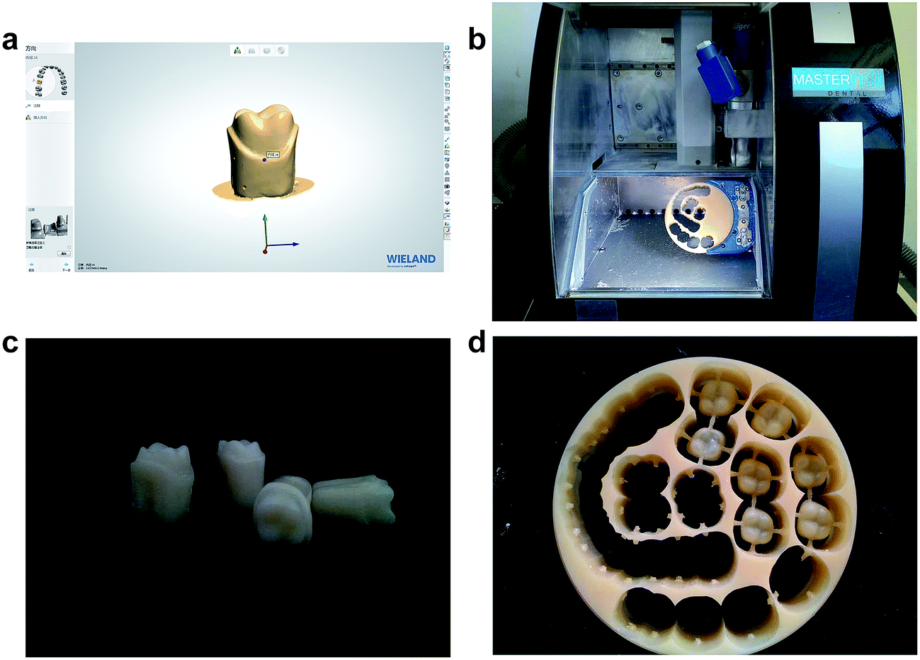 | ||
| Fig. 1 Preparation of the PMMA abutments and crowns (a). Scanning of a prepared maxillary first molar (b), milling the dental resin disk, PMMA abutment tooth (c), and PMMA crowns with different thicknesses (d). | ||
![[thin space (1/6-em)]](https://www.rsc.org/images/entities/char_2009.gif) :25 mL. The invested molds were heated at a rate of 10 °C min−1, from room temperature to 850 °C, for 1 h in an electric furnace (Kavo EWL, Typ5625, Germany), and the PMMA crowns were melted down. Consecutively, the invested molds were immediately transferred into a heat-press furnace (Empress EP600, Ivoclar Vivadent) which was preheated to 700 °C following the instruction of manufacturer. The lithium disilicate ceramic ingots (EMAX and ELDC) were heat-pressed, in accordance with the manufacture's guidelines and previous reports,15,19 respectively. Subsequently, the investment molds were removed from the pressing furnace and cooled for 2 h in a ventilated room followed by devesting performed by sandblasting with Al2O3 particles (50 μm) at a pressure of 0.2 MPa. The reacted layer was removed through immersing the pressed specimens in an aqueous solution containing 0.6% hydrofluoric acid solution (Invex Liquid, Ivoclar AG). Then, the specimens were ultrasonically cleaned by distilled water for 10 min and dried using oil-free air. Surface glazing (EMAX Ceram Glasurpaste, Ivoclar-Vivadent) and firing at 725 °C was performed. Totally, sixty monolithic lithium disilicate glass ceramic crowns with different thicknesses were fabricated, with six specimens in each group.
:25 mL. The invested molds were heated at a rate of 10 °C min−1, from room temperature to 850 °C, for 1 h in an electric furnace (Kavo EWL, Typ5625, Germany), and the PMMA crowns were melted down. Consecutively, the invested molds were immediately transferred into a heat-press furnace (Empress EP600, Ivoclar Vivadent) which was preheated to 700 °C following the instruction of manufacturer. The lithium disilicate ceramic ingots (EMAX and ELDC) were heat-pressed, in accordance with the manufacture's guidelines and previous reports,15,19 respectively. Subsequently, the investment molds were removed from the pressing furnace and cooled for 2 h in a ventilated room followed by devesting performed by sandblasting with Al2O3 particles (50 μm) at a pressure of 0.2 MPa. The reacted layer was removed through immersing the pressed specimens in an aqueous solution containing 0.6% hydrofluoric acid solution (Invex Liquid, Ivoclar AG). Then, the specimens were ultrasonically cleaned by distilled water for 10 min and dried using oil-free air. Surface glazing (EMAX Ceram Glasurpaste, Ivoclar-Vivadent) and firing at 725 °C was performed. Totally, sixty monolithic lithium disilicate glass ceramic crowns with different thicknesses were fabricated, with six specimens in each group.2.2 Bonding and cementation procedure
Before cementation with the adhesive resin, the inner surfaces of the crowns were cleaned using 36% phosphoric acid etching gel, followed by etching with 5% hydrofluoric acid (IPS Ceramic Ätzgel, Ivoclar Vivadent) for 20 s. Then, the etched ceramic surface was thoroughly cleaned using water spray for 60 s. A silane coupling agent (Monobond Plus, Ivoclar Vivadent) was applied to the inner surface of each crown immediately and air dried after 60 s. Then, the ceramic crowns were cemented to PMMA abutments using the luting resin cement (VariolinkII, Ivoclar Vivadent). The excess luting cement at the margin was removed carefully, and an air-inhibiting gel was applied along the margin. The composite resin cement was lightly cured (EliparTM S10 3M, Germany) for 30 s on each side (labial, lingual, mesial, and distal) with 500 mW cm−2 light intensity. After 15 min, the cemented crowns were vertically embedded by self-curing resin that had already been poured into a stainless-steel model (22 mm diameter, 10 mm in height), leaving the cervical margins evenly exposed 2 mm above the acrylic resin surface. 1 h after the cementation, all the specimens were preserved in distilled water at 37 °C for 24 h.2.3 Fracture load test
Prior to the fracture test, all the specimens were subjected to 10000 times thermal cycling between 5 and 55 °C (dwelling time at each temperature 30 s, DC0515 FANGRUI Shanghai China), which aims at simulating artificial aging. Then, all the specimens were placed in a universal test machine (AGS-10KN Japan) for the fracture test. A stainless-steel ball (6 mm diameter) was used to apply a compressive load on the occlusal surface along the long axis of abutment at a crosshead speed of 1 mm min−1. This compressive load was centered on the midline fissure of each crown, so it was applied to the triangular ridges of both lingual and facial cusps establishing a three-point contact. In order to maintain the stability, the contact areas were tested thin red occlusion foil papers (Zhangjiang Biologic Material Shanghai, China). Additionally, a piece of polyethylene forming foil, with 1 mm thickness, was placed between the crown and the loading ball to achieve a uniform distribution of the force,27 The maximum load (newton [N]) until crown fracture was recorded by TestXpert II (Zwick, Ulm, Germany).
2.4 Fracture mode and fractographic analysis
The fracture mode of crowns was observed using a stereomicroscope (M205A, Leica, Heerbrugg, Germany). The representative specimens were selected and examined by scanning electron microscopy (SEM) (FE-SEM S-4800, Hitachi). Prior to observation, all the crowns were spruced in an ultrasonic alcohol bath (BioSonic UC50D, Whaledent, USA) for 10 min and coated with gold. The analysis was initiated from the edge of the broken crown, from the upper part to the inner surface and ending at the other side of the crown. Different magnifications of the stereomicroscope and illumination angles were adjusted to detect the characteristic marks of the crack clearly. Finally, photomicrographs were recorded and fracture morphology was analyzed according to the description and methods employed for the brittle materials.24,25,28,292.5 Statistical analysis
Mean and standard deviation of the fracture load value (F(u)) for each group were calculated. The normal distribution of the data was verified by the Kolmogorov–Smirnov test. Besides, the effects of the material and thickness on the F(u) of the glass-ceramic crowns were analyzed using two-way ANOVA, followed by the Tukey's Honest Significant Difference (HSD) test. The differences in F(u) of ELDC or EMAX ceramic crowns at different thicknesses were analyzed by one-way ANOVA variance analysis. Moreover, the differences between two lithium disilicate ceramic crowns at the same thickness were analyzed by the Student's t-test. All the statistical analyses were performed by SPSS 19.0 and the level of significance was set at 0.05.3. Results
3.1 Fracture load
The average F(u) values of the EMAX ceramic crowns ranged from 685–1827 N as thickness increased from 0.5 mm to 1.5 mm, and that for ELDC ceramic crowns from 700–1791 N (Table 1). Using two-way ANOVA, the effects of the ceramic materials and thickness of the crowns on the F(u) values of the monolithic crowns were analyzed. Results demonstrated that the influence of the thickness factor on the F(u) values was statistically significant (P < 0.01). The type of ceramic materials had no significant effect on F(u) values, and no interaction was observed between two variables (P > 0.05) (Table 2). Through comparing the F(u) values of ELDC and EMAX crowns at the same thickness, no significantly difference was found (P > 0.05) (Table 1), indicating that ELDC and EMAX ceramic had similar ability to resistant fracture. One-way ANOVA results of F(u) values of lithium disilicate ceramic crowns proved that there were significant differences in F(u) values as thicknesses varied in both ELDC and EMAX crowns (P < 0.01) (Tables 3 and 4). The 0.5 mm crowns showed the lowest F(u) values (P < 0.05). In general, an increase in the F(u) values was found with statistical significance as thickness of the crown increased for both ELDC and EMAX. No significant difference between 1.2 mm and 1.5 mm groups was found (Fig. 2).| 0.5 mm | 0.8 mm | 1.0 mm | 1.2 mm | 1.5 mm | |
|---|---|---|---|---|---|
| ELDC (n = 6) | 700.6 ± 110.1 | 1102.5 ± 202.1 | 1340.7 ± 222.2 | 1522.3 ± 219.1 | 1791.5 ± 287.0 |
| EMAX (n = 6) | 685.1 ± 116.2 | 1106.7 ± 250.7 | 1337.7 ± 198.3 | 1526.7 ± 191.2 | 1827.3 ± 337.6 |
| t | 0.237 | −0.032 | 0.025 | −0.036 | −0.198 |
| P | 0.817 | 0.975 | 0.981 | 0.972 | 0.847 |
| Source | Sum of squares | df | Mean square | F | P |
|---|---|---|---|---|---|
| a R-square = 0.776 (adjusted R-square = 0.735). | |||||
| Corrected model | 862076.02a |
9 | 957 862.34 | 19.20 | 0.000 |
| Intercept | 10048277.00 |
1 | 100 484 276.80 | 2013.76 | 0.000 |
| Materials × thickness | 4307.83 | 4 | 1076.96 | 0.022 | 0.999 |
| Materials | 400.42 | 1 | 400.42 | 0.008 | 0.929 |
| Thickness | 8616052.77 |
4 | 2 154 013.19 | 43.168 | 0.000 |
| Error | 2494947.17 |
50 | 49898.94 |
||
| Total | 111599985.00 |
60 | |||
| Corrected total | 11115708.20 |
59 | |||
| Source | Sum of squares | df | Mean square | F | P |
|---|---|---|---|---|---|
| Between groups | 4143038.46 |
4 | 1035759.61 |
22.25 | 0.00 |
| Within groups | 1163465.00 |
25 | 46538.60 |
||
| Total | 5306503.46 |
29 |
| Source | Sum of squares | df | Mean square | F | P |
|---|---|---|---|---|---|
| Between groups | 4477322.13 |
4 | 1 119 330.53 | 21.02 | 0.00 |
| Within groups | 1331482.17 |
25 | 53259.29 |
||
| Total | 5808804.30 |
29 |
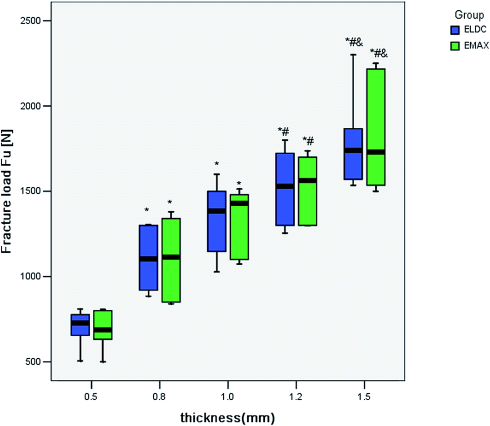 | ||
| Fig. 2 Box plot of fracture load values F(u) of ELDC and EMAX crowns with different thicknesses. (*) indicated a significant difference compared with 0.5 mm groups (P < 0.01). (#) indicated a significant difference compared with 0.8 mm groups (P < 0.01). (&) indicated a significant difference compared with 1.0 mm groups (P < 0.01). | ||
3.2 Fractographic analysis
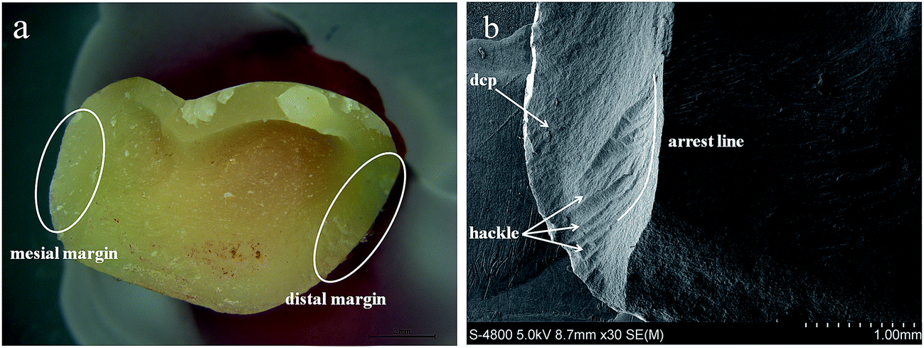
In the present study, all the monolithic crowns failed due to a complete bulk fracture of the crowns with a mixed cohesive/adhesive failure. Stereomicroscope results of the fractured surface from the coronal and sagittal planes demonstrated indicated that the crack path propagated from occlusal surface to the mesiodistal marginal ridges, results in the splitting of most specimens into several pieces (Fig. 3a and b). In addition, in most cases, the cement was left on both tooth and the crown side. SEM analysis confirmed that the crack penetrated from the occlusal surface to the other side of the crown. A small fuzzy area was observed at the crack initiation site, which occurred at the crack surface and lingual edge successive to the fractured crowns (Fig. 4a). The hackles demonstrated the origin of the pressure and the main direction of crack propagation (dcp) (Fig. 4b). Besides, the crack initiation site was observed as a small chip that occurred on the crack surface and lingual edge after the crowns fractured (Fig. 5a and b).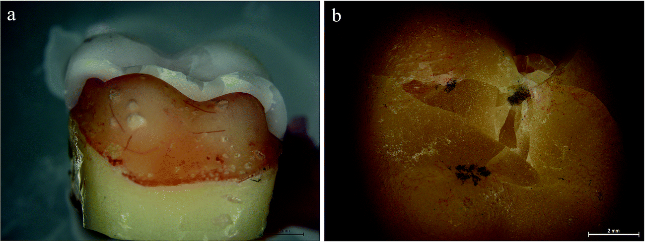 | ||
| Fig. 3 Stereomicroscope images showed that the primary fracture modes of the ELDC (a) and EMAX (b) crowns were bulk fractures. The cracks propagated perpendicularly from the occlusal fissures downward to the inner surface, and the crack path extended along both the mesiodistal and buccal fissures. Consequently, the crown failed into several pieces. | ||
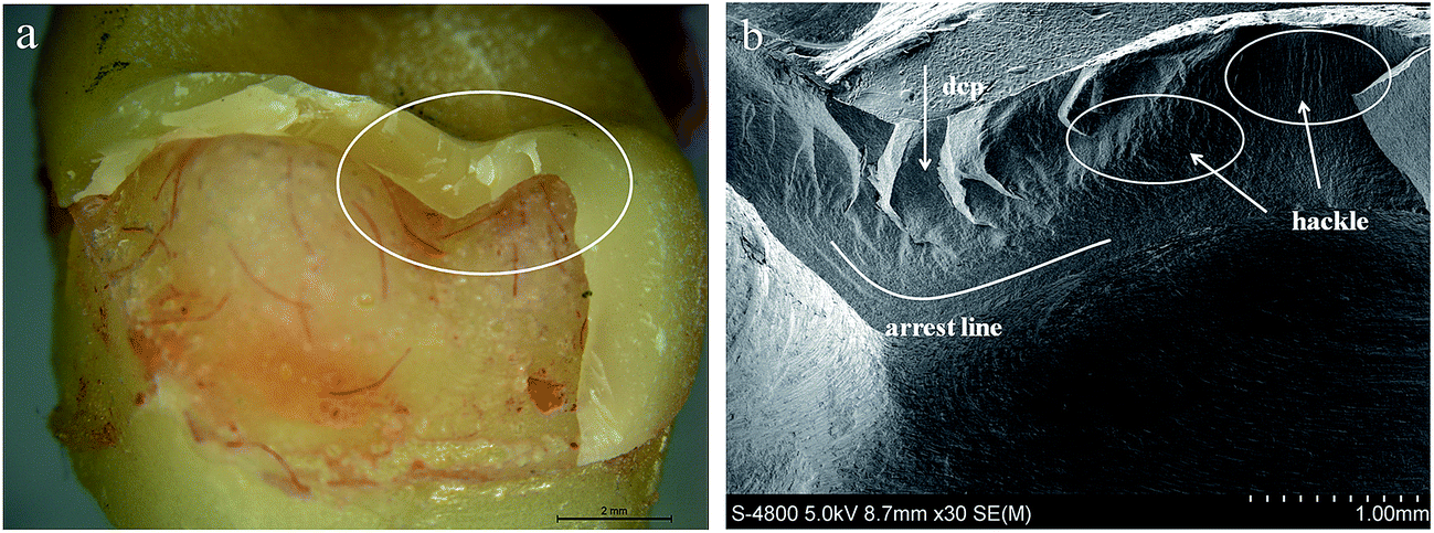 | ||
| Fig. 4 Stereomicroscope and SEM images of the fractured surface (a). High magnification of area indicated by the white ellipse in the image (b). The hackle and arrest line on the occlusal surface confirmed the dcp on the fracture surface extending from top to bottom (SEM, 30×). | ||
 | ||
| Fig. 5 Stereomicroscope images of the chip on a fragment (a). Additional hackles were found on both mesial and distal side of the broken surface (b). The arrest lines indicated the originating crack, marked by white curves and the dcp demonstrated that the crack hackle originated from the exterior and extended perpendicularly to the inner margin (SEM, 30×). | ||
4. Discussion
This study investigated the fracture behaviors of two monolithic lithium disilicate ceramic crowns, which especially focused on the relationship between the fracture behavior and thickness of monolithic crowns. The monolithic lithium disilicate crown has reportedly resolved the chipping issue in bilayered crowns.30 The frequently used thickness for bilayered crowns was 1.5–2.0 mm in the majority reported studies.31,32 Because lithium disilicate glass ceramics combined the aesthetic potential and suitable mechanical property for making dental crowns, the addition of veneer porcelain for aesthetic requirement was not essential. Accordingly, the remove of nature tooth structure can be reduced, which might be beneficial for tooth health, especially in young patients with the aim to prevent the excessive removal of the natural tooth tissue. Moreover, the application in the monolithic crown form endows simplicity of production. Therefore, a better understanding of the relationship between fracture resistance and thickness of monolithic lithium disilicate crowns was critical in conservative dentistry.In most cases, wax crown patterns made by hands were used for fabricating ceramic crowns by applying heat pressing method. However, it was challenging to maintain the accuracy in thickness and homogeneous among the crowns. Therefore, in the present study, all the crown patterns were fabricated by CAD/CAM technology using PMMA material for accurate control of crown thickness. With the consideration of the fact that the individual differences of the human teeth such as the dimensions, form, and quality may increase the variability of the fracture resistance,33 the PMMA molar abutments fabricated by CAD/CAM technology ensured the homogeneity and uniformity in each group in the present study. Besides, artificial periodontium was not applied to surround the abutment root as some authors postulated that single crowns with artificial periodontium would reduce the axial force when the specimen moved in the surrounding elastic layer, and the consequent mobility was neither regulated nor optimized.34
The present study revealed an average F(u) values ranging from 685–1827 N for EMAX crowns and 700–1791 N for ELDC crowns as the thickness varied from 0.5 mm to 1.5 mm. The average occlusal bite force measured at the first mandibular molar was 633 N for males and 527 N for females.35 In other reports, the average high biting force in the posterior region was reported as 597 N for females and 847 N for males with a maximum of about 900 N.36,37 Therefore, regarding the results of the fracture test in the present study (Table 2), except 0.5 mm group (700.6 ± 110.11 N for ELDC and 685.17 ± 116.15 N for EMAX), the other thickness groups seemed to achieve a higher F(u) than the reported biting force in the posterior region. Under physiological conditions, the extreme force will be distributed in several teeth rather than a single occlusal contact. However, under specific clinical conditions such as bruxism, the crowns may be subjected to the worst challenge during mastication. Therefore, although the results of the 0.8 mm thickness groups demonstrated high average fracture values (1102.50 ± 202.14 N for ELDC and 1106.67 ± 250.73 N for EMAX) than that of the reported occlusal bite force in the posterior regions, it did not indicate that 0.8 mm thickness could be safely applied, since the values of some specimens in these groups were lower than the reported occlusal bite force value.
The fracture resistance of EMAX and ELDC were not statistically different at the same thickness. An increase in the F(u) was observed as thickness increased. Moreover, the extent of change was similar for EMAX and ELDC crowns. In addition, no statistical difference in F(u) values between 1.2 mm and 1.5 mm groups was revealed, implying that an increased 1.5 mm thickness would not expect an improved fracture resistance. As a result, according to the principle of conservative dentistry, the preparation of a tooth for ELDC or EMAX crowns can be reduced from 1.5 mm to 1.2 mm, without causing an increased fracture risk. However, the result might not represent the clinical situation as only a perpendicular force was applied. For a better understanding of the fracture resistance of the tested materials, other impact factors, i.e. lateral force and mechanical fatigue, were expected to be taken into consideration.
Different crack initiations (including cone crack, quasi-plastic, and radial crack) were detected in this study. Compared with the bilayer structure (veneer porcelain–core ceramic), monolithic lithium disilicate glass ceramic showed a more homogenous structure at the fractured surface, without pores or large voids. The majority fracture mode for the ELDC and EMAX crowns constituted complete cracking into two or three pieces (Fig. 3a and b). The hackles observed below the surface demonstrated that the cracks started from the occlusal surface between the contact points and grew deeply into the inner surface following the applied load in the perpendicular direction. The arrest lines were present in the form of ridges on the fracture surfaces, indicating the joining of the cracks at this intersection (Fig. 4a and b). At the same time, the hackle also appeared in the region in proximity to the cervical margin, which represented as stress concentration area and one of the weakest parts of the crown structure (Fig. 5a and b). The results also confirmed to the description of monolithic ceramic crowns in the previously published report.11
As for thinner crowns, the radial cracks generated and extended easily to cause a catastrophic fracture, which might explain the lowest F(u) value of the 0.5 mm groups. Conversely, for thicker groups, the cone crack mechanisms became more predominant. The thicker crowns showed high fracture loads due to high fracture energy, which was prone to generate added bifurcations in order to release high fracture energy.38,39 Consequently, the increase of the crowns thickness might contribute to reducing the initiation of the radial cracks. Within the limitations of this study, it may be advantageous to increase the thickness up to a minimum of 1.0 mm, which might reduce the first radial cracks.
Several studies proved that thermal cycling (TC) fatigue in simulating oral conditions could accelerate the damage of ceramic materials, ascribing to the periodic stress in temperature weakening the mechanical properties.40 In the present work, all the crowns suffered 10000 times thermal cycling before the fracture test, for a simply simulation of the clinical condition used in many studies.41,42 As the primary interest of this study was to investigate how the fracture behaviors of two types of monolithic lithium disilicate ceramic crowns related to different thicknesses, other influencing factors such as mechanical aging or dynamical loading method were not included in the present study. Although standard tooth abutments and crowns used in the present study could ensure the homogeneity of the investigated targets, the configuration of crowns in clinical practice would be more complex. To better understand and predict the clinical performance of the two ceramic crowns, future in vitro and in vivo studies should be conducted to focus on the factors mentioned above for a comprehensive assessment of the fracture behavior of monolithic lithium disilicate ceramic crowns.
5. Conclusions
Within the limitations of the present study, it can be concluded that the thickness played a major role in determining the fracture resistance of monolithic lithium disilicate ceramic crowns. ELDC monolithic crowns showed similar fracture behavior in comparison with the EMAX crowns. An increase in the fracture resistance would be achieved when increasing ceramic thickness and a thickness range 1.0–1.2 mm was recommended for fabricating monolithic crowns using EMAX or ELDC ceramic in the posterior teeth.Acknowledgements
This study was supported by the National Natural Science Foundation of China (51472269), Science and Technology Innovation Project of Shaanxi province (2012KTCG04-09) and Program for Changjiang Scholars and Innovative Research Team in University (No. IRT13051).References
- M. A. Rosenblum and A. Schulman, J. Am. Dent. Assoc., JADA, 1997, 128, 297–307 CrossRef CAS PubMed.
- S. Wolfart, S. Eschbach, S. Scherrer and M. Kern, Dent. Mater., 2009, 25, e63–71 CrossRef CAS PubMed.
- H. J. Conrad, W. J. Seong and I. J. Pesun, J. Prosthet. Dent., 2007, 98, 389–404 CrossRef CAS PubMed.
- M. J. Heffernan, S. A. Aquilino, A. M. Diaz-Arnold, D. R. Haselton, C. M. Stanford and M. A. Vargas, J. Prosthet. Dent., 2002, 88, 4–9 CrossRef PubMed.
- K. Klosa, S. Wolfart, F. Lehmann, H. J. Wenz and M. Kern, J. Adhes. Dent., 2009, 11, 127–135 CAS.
- P. F. Motro, P. Kursoglu and E. Kazazoglu, J. Prosthet. Dent., 2012, 108, 231–237 CrossRef CAS PubMed.
- J. M. Lima, A. C. Souza, L. C. Anami, M. A. Bottino, R. M. Melo and R. O. Souza, Dent. Mater., 2013, 29, 1063–1072 CrossRef CAS PubMed.
- D. Edelhoff and J. A. Sorensen, Int. J. Periodontics Restorative Dent., 2002, 22, 241–249 Search PubMed.
- B. Seydler, S. Rues, D. Muller and M. Schmitter, Clin. Oral Investig., 2014, 18, 1165–1171 CrossRef PubMed.
- P. C. Guess, A. Kulis, S. Witkowski, M. Wolkewitz, Y. Zhang and J. R. Strub, Dent. Mater., 2008, 24, 1556–1567 CrossRef CAS PubMed.
- J. H. Kim, S. J. Lee, J. S. Park and J. J. Ryu, Implant Dent., 2013, 22, 66–70 CrossRef PubMed.
- K. Zhao, Y. R. Wei, Y. Pan, X. P. Zhang, M. V. Swain and P. C. Guess, Dent. Mater., 2014, 30, 164–171 CrossRef CAS PubMed.
- B. Taskonak and A. Sertgöz, Dent. Mater., 2006, 22, 1008–1013 CrossRef CAS PubMed.
- K. Harada, A. J. Raigrodski, K. H. Chung, B. D. Flinn, S. Dogan and L. A. Mancl, J. Prosthet. Dent., 2016, 116, 257–263 CrossRef CAS PubMed.
- P. C. Guess, R. A. Zavanelli, N. R. Silva, E. A. Bonfante, P. G. Coelho and V. P. Thompson, Int. J. Prosthodont., 2010, 23, 434–442 Search PubMed.
- M. Kern, M. Sasse and S. Wolfart, J. Am. Dent. Assoc., JADA, 2012, 143, 234–240 CrossRef PubMed.
- F. Wang, J. Gao, H. Wang and J. H. Chen, Mater. Des., 2010, 31, 3270–3274 CrossRef CAS.
- K. Yuan, F. Wang, J. Gao, X. Sun, Z. X. Deng, H. Wang and J. H. Chen, J. Non-Cryst. Solids, 2013, 362, 7–13 CrossRef CAS.
- F. Wang, Z. G. Chai, Z. X. Deng, J. Gao, H. Wang and J. H. Chen, PLoS One, 2015, 10, e0126896 Search PubMed.
- N. Nawafleh, M. Hatamleh, S. Elshiyab and F. Mack, J. Prosthodontics, 2016, 25, 116–126 CrossRef PubMed.
- J. R. Kelly, J. Prosthet. Dent., 1999, 81, 652–661 CrossRef CAS PubMed.
- Y. Zhang, J. W. Kim, S. Bhowmick, V. P. Thompson and E. D. Rekow, J. Biomed. Mater. Res., Part B, 2009, 88, 402–411 CrossRef PubMed.
- P. C. Guess, S. Schultheis, E. A. Bonfante, P. G. Coelho, J. L. Ferencz and N. R. Silva, Dent. Clin. North Am., 2011, 55, 333–352 CrossRef PubMed.
- L. H. Schlichting, H. P. Maia, L. N. Baratieri and P. Magne, J. Prosthet. Dent., 2011, 105, 217–226 CrossRef CAS PubMed.
- P. C. Guess, S. Schultheis, M. Wolkewitz, Y. Zhang and J. R. Strub, J. Prosthet. Dent., 2013, 110, 264–273 CrossRef CAS PubMed.
- A. Albosefi, M. Finkelman and R. Zandparsa, J. Prosthodontics, 2014, 23, 296–301 CrossRef PubMed.
- T. Sun, S. Zhou, R. Lai, R. Liu, S. Ma, Z. Zhou and S. Longquan, J. Mech. Behav. Biomed. Mater., 2014, 35, 93–101 CrossRef CAS PubMed.
- G. Quinn, Fractography of ceramics and glasses, A NIST recommended practice guide, National Institute of Standards and Technology, Washington, DC, May 2007 Search PubMed.
- A. S. T. M. C.-a, Standard practice for fractography and characterization of fracture origins in advanced ceramics, Annual book of standards, 15.01., ASTM International, West Conshohoken, PA, 2005 Search PubMed.
- I. Sailer, A. Feher, F. Filser, L. J. Gauckler, H. Luthy and C. H. Hammerle, Int. J. Prosthodont., 2007, 20, 383–388 Search PubMed.
- S. Reich and O. Schierz, Clin. Oral Investig., 2013, 17, 1765–1772 CrossRef PubMed.
- P. Marquardt and J. R. Strub, Quintessence Int., 2006, 37, 253–259 Search PubMed.
- C. F. Stappert, P. C. Guess, S. Chitmongkolsuk, T. Gerds and J. R. Strub, J. Oral Rehabil., 2006, 33, 698–705 CrossRef CAS PubMed.
- S. D. Heintze, A. Cavalleri, G. Zellweger, A. Buchler and G. Zappini, Dent. Mater., 2008, 24, 1352–1361 CrossRef CAS PubMed.
- B. K. Al-Zarea, Med. Princ. Pract., 2015, 24, 142–146 CrossRef PubMed.
- A. Waltimo and M. Kononen, Scand. J. Dent. Res., 1994, 102, 372–375 CAS.
- A. Waltimo and M. Kononen, Acta Odontol. Scand., 1995, 53, 254–258 CrossRef CAS PubMed.
- M. Groten and F. Huttig, Int. J. Prosthodont., 2010, 23, 429–431 Search PubMed.
- R. P. Christensen and B. J. Ploeger, J. Am. Dent. Assoc., JADA, 2010, 141, 1317–1329 CrossRef PubMed.
- M. Khoroushi and M. Mansoori, ISRN Dent., 2012, 2012, 204813 Search PubMed.
- M. S. Gale and B. W. Darvell, J. Dent., 1999, 27, 89–99 CrossRef CAS PubMed.
- A. L. Morresi, M. D'Amario, M. Capogreco, R. Gatto, G. Marzo, C. D'Arcangelo and A. Monaco, J. Mech. Behav. Biomed. Mater., 2014, 29, 295–308 CrossRef CAS PubMed.
Footnote |
| † Those authors contributed equally to this work. |
| This journal is © The Royal Society of Chemistry 2017 |