
 Open Access Article
 This Open Access Article is licensed under a
 Creative Commons Attribution 3.0 Unported Licence
Growth of Zr/N-codoped TiO2 nanorod arrays for enhanced photovoltaic performance of perovskite solar cells
Zhenlong Zhanga,
Junfeng Lia,
Xiaoli Wanga,
Jianqing Qina,
Wenjia Shia,
Yuefeng Liua,
Huiping Gaoa and
Yanli Mao *ab
*ab
aSchool of Physics and Electronics, Henan University, Kaifeng 475004, China. E-mail: ylmao1@163.com; Tel: +86-371-23893703
bInstitute for Computational Materials Science, Henan University, Kaifeng 475004, China
First published on 27th February 2017
Abstract
In this paper, Zr and N co-doped TiO2 (Zr/N–TiO2) nanorod arrays were synthesized using a hydrothermal method and perovskite solar cells were fabricated using them as an electron transfer layer. The solar cells based on Zr/N–TiO2 presented an enhanced performance compared with those based on un-doped TiO2. The solar cell performance was optimized by changing the Zr doping content. The efficiency of solar cells based on Zr/N–TiO2 with a Zr doping content of 1% (Zr/Ti, atomic ratio) has been achieved at 12.6%, which was 31.6% higher than that of solar cells based on un-doped TiO2. To get an insight into the enhancement, some investigations were carried out. The results indicate that the larger open voltage (Voc) could be due to the larger conduction band offset resulting from the smaller energy band gap for Zr/N–TiO2, and the enlarged short current (Isc) could be attributed to the faster electron transfer and reduced recombination rate for Zr/N–TiO2 NRs. These induce the enhancement of solar cell efficiency.
1. Introduction
Recently, perovskite solar cells (PSCs) have attracted more attention due to their high efficiency, low cost, and long charge diffusion length.1–4 The power conversion efficiency (PCE) of perovskite solar cells has increased to over 22% (ref. 5) within a very short period of time. Typically, mesoporous PSCs are composed of three layers, the electron transfer material (ETM) layer, the perovskite material layer, and the hole transfer material (HTM) layer. TiO2 has been widely utilized as an ETM in PSCs due to its chemical inertness, photostability, nontoxicity and low cost production.6,7 However, the wide band gap (3.2 eV) and rapid recombination rate of photogenerated carriers limit the applications of TiO2.One of the strategies to reduce the recombination rate of photogenerated carriers is element doping of TiO2. It has been reported that metal element doping, such as Mg–TiO2,8 Cd–TiO2,9 Zr–TiO2,10 W–TiO2,11 etc., and nonmetal doping, such as F–TiO2,12 can effectively improve the performance of electron transfer layer in PSCs. Recently, theoretical calculations and experimental data have demonstrated that the recombination rate of photogenerated carriers in TiO2 can be further reduced by metal and nonmetal co-doping, such as Zr/N co-doping.13–16 The Zr/N co-doping TiO2 could enhance the energy conversion efficiency of dye-sensitized solar cells (DSSCs), narrow the band gap, and improve the absorption in visible light range.16 However, there are no reports on the applications of Zr/N co-doping TiO2 in perovskite solar cells until now.
In our previous paper,17 we investigated the effect of doping N content on the performance of perovskite solar cells, in which the solar cells with the doping N content of 1% (N/Ti, nominal atomic ratio) presented the best performance. Based on the previous work, in the present study, we synthesized Zr and N co-doped TiO2 (Zr/N–TiO2) nanorod arrays and fabricated the perovskite solar cells using them as electron transfer layer. The solar cell performance was optimized by changing the Zr doping contents. The PCE of solar cells based on Zr/N–TiO2 with the Zr doping content of 1% (Zr/Ti, nominal atomic ratio) has been achieved 12.6%, which was 31.6% higher than that of solar cells based on un-doped TiO2. The possible mechanisms of the enhancement were investigated.
2. Experimental
2.1 Growth of TiO2 nanorod arrays
FTO-coated glass substrate was patterned by etching with Zn metal powder and 2 M HCl diluted in deionized water, and cleaned by sonication for 20 min in detergent, acetone, 2-propanol, and ethanol, respectively. Oxygen plasma was subsequently used to treat the substrate for 20 min. A compact layer of TiO2 was formed on FTO by treating the substrate in a 0.2 M aqueous solution of TiCl4 at 70 °C for 30 min. TiO2 nanorods (NRs) were grown on the compact layer by a hydrothermal method.18 In brief, 20 mL of 37% hydrochloric acid and 20 mL of deionized water were mixed. Subsequently 0.7 mL of titanium(IV) n-butoxide (99%, Aladdin reagent) was added and stirred for 30 min. In the next step, nothing was added to the solution for the growth of un-doped TiO2, a certain amount of CO(NH2)2 (N/Ti, nominal atomic ratio, 1%) was added for the growth of N doped TiO2 (N–TiO2), and pre-calculated amount of CO(NH2)2 (N/Ti, nominal atomic ratio, 1%) and Zr(NO3)4·5H2O (Zr/Ti, nominal atomic ratio, 0.5%, 1%, 3%, and 5%) were added for the growth of Zr/N codoped TiO2 (Zr/N–TiO2). The mixed solution and a compact layer coated FTO substrate was sealed in a stainless steel autoclave. The sealed autoclave was placed inside the oven preheated to 170 °C for several hours. After cooling down to room temperature, the TiO2 nanorods film was rinsed with ethanol and deionized water, and annealed at 500 °C for 60 min.2.2 Materials preparation
Methylammonium iodide (CH3NH3I) was synthesized using a previously reported method.19 Typically, aqueous solution of hydroiodic acid (HI) (5 mL, 57 wt% in water, Aladdin Reagent) was reacted with methylamine (CH3NH2) (12 mL, 33 wt% in absolute ethanol, Aladdin reagent) at 0 °C for 2 h with constant stirring under nitrogen atmosphere. Methylammonium iodide was crystallized by removing the solvent with a rotary evaporator. The generated white powder was washed with diethyl ether for three times and dried in vacuum for overnight at 60 °C. The perovskite precursor solution was prepared by dissolving CH3NH3I and lead(II) chloride (PbCl2) in anhydrous N,N-dimethylformamide (DMF) at a 3![[thin space (1/6-em)]](https://www.rsc.org/images/entities/char_2009.gif) :1 molar ratio at 60 °C.
:1 molar ratio at 60 °C.
2.3 Solar cell fabrication
The perovskite precursor solution was spin-coated on the annealed TiO2 film at 2000 rpm for 60 s in an argon-filled glove box. The sample was dried on a hotplate at 110 °C for 60 min. The hole-transporter layer was deposited by spincoating a solution of 2,2′,7,7′-tetrakis(N,N-di-p-methoxyphenyl-amine)9,9′-spirobifluorene (spiro-MeOTAD) at 2000 rpm for 60 s. The spiro-MeOTAD solution was prepared by dissolving 72.3 mg of spiro-MeOTAD in 1 mL of chlorobenzene, to which 28.8 μL of 4-tert-butylpyridine and 17.5 μL of lithium bis(trifluoromethanesulfonyl)imide (Li-TFSI) solution (520 mg Li-TSFI in 1 mL acetonitrile, Aladdin reagent) were added. Finally, a gold layer with a thickness of 80 nm was thermally evaporated on top of the device.2.4 Characterization
X-ray diffraction (XRD) patterns were recorded on a DX-2700 diffractometer with Cu Kα radiation with λ = 0.1542 nm. Photocurrent–voltage (I–V) measurements were performed using a Keithley 2440 Sourcemeter under AM 1.5 G illumination from a Newport Oriel Solar Simulator with an intensity of 100 mW cm−2. The active area was 0.1 cm2 determined by a shadow mask. Morphologies and microstructures were observed with a scanning electron microscope (SEM, JEM-7001F, JEOL) equipped with an energy dispersive spectrometer (EDS). UV-vis absorption spectra were collected on a UV-vis spectrophotometer (Varian Cary 5000). Steady-state photoluminescence (PL) and time-resolved photoluminescence (TRPL) measurements were acquired with a FLS 980 E fluorometer (Edinburgh Photonics), with an excitation source of 515 nm diode laser. The electrochemical impedance spectroscopy (EIS) was performed under a forward bias of 0.6 V under 1 sun illumination conditions with an electrochemical workstation (CHI660e, Shanghai CHI Co., Ltd.) with the frequency range from 1 Hz to 300 kHz. The magnitude of the alternative signal was 10 mV.3. Results and discussion
We synthesized un-doped, N doped, and Zr/N co-doped TiO2 nanorod arrays, and fabricated perovskite solar cells using them as an electron transfer material. I–V measurements were performed by reverse scan (RS) and forward scan (FS). The photovoltaic parameters were obtained by the average of RS and FS for each device. The short current (Isc), open voltage (Voc), fill factor (FF), and power conversion efficiency (PCE) of the solar cells were obtained by an average of the data from 20 pieces of devices. Fig. 1A shows the dependence of PCE on Zr doping contents. It displays that the PCE of solar cells is the maximum at the Zr doping content of 1% (Zr/Ti, nominal atomic ratio). There is an optimal doping content for Zr incorporation. When the content of Zr was lower than its optimal level, the Zr impurity energy level would be a separation center, which could improve the separation of photoinduced carriers. In contrast, when the content of Zr was higher than its optimal level, Zr impurity energy level would be a recombination center, which could increase the recombination of photoinduced carriers.14,20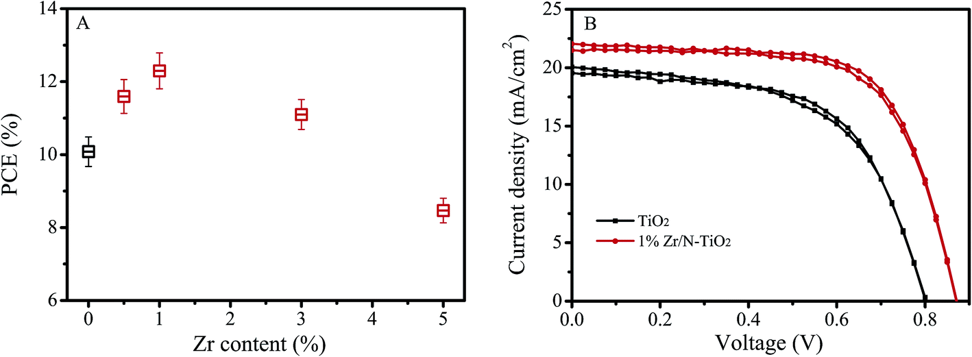 | ||
| Fig. 1 (A) Dependence of solar cells PCE on Zr doping contents. (B) I–V curves of best performance solar cells based on un-doped TiO2 and 1% Zr/N–TiO2 NRs. | ||
Table 1 shows the photovoltaic parameters of the solar cells based on un-doped TiO2, 1% N–TiO2, and 1% Zr/N–TiO2 NRs. The photovoltaic parameters of solar cells on 1% Zr/N–TiO2 NRs are enhanced compared with those of solar cells on un-doped TiO2 and 1% N–TiO2 NRs. The high PCE of 12.6% has been obtained for the solar cells on 1% Zr/N–TiO2 NRs, which is 31.6% higher than that of solar cells on un-doped TiO2 NRs. Fig. 1B shows the I–V curves of best performance solar cells based on un-doped TiO2 and 1% Zr/N–TiO2 NRs.
| Sample | Voc (V) | Jsc (mA cm−2) | FF | PCE (%) |
|---|---|---|---|---|
| TiO2 | 0.80 ± 0.02 | 19.2 ± 0.6 | 0.62 ± 0.03 | 9.5 ± 0.3 |
| 1% N–TiO2 | 0.82 ± 0.01 | 20.5 ± 0.7 | 0.65 ± 0.02 | 10.9 ± 0.2 |
| 1% Zr/N–TiO2 | 0.88 ± 0.03 | 21.6 ± 0.7 | 0.66 ± 0.02 | 12.5 ± 0.1 |
To explain the enhancement phenomenon, we carried out some investigations. Fig. 2 shows the XRD patterns of un-doped TiO2 and 1% Zr/N–TiO2 NRs. The peaks labelled with stars were assigned to SnO2 (JCPDS card, 41-1445) on FTO substrate. The diffraction peak at 36.1° is assigned to the (101) planes of rutile TiO2 (JCPDS card, 21-1276).21 Only one peak appears in the XRD patterns, which suggests that almost all the crystallites grew preferentially along the (101) plane parallel to the substrate surface.22 For the XRD patterns of Zr/N–TiO2 NRs, Zr peaks did not observed, which might be due to the homogeneous distribution of Zr with Ti in the samples23 and small amount of Zr doping contents.
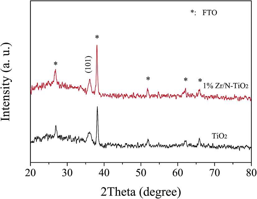 | ||
| Fig. 2 XRD patterns of un-doped TiO2 and 1% Zr/N–TiO2 NRs. | ||
Fig. 3 shows the XPS spectra of 1% Zr/N–TiO2 NRs. The peaks located at 458.5 and 464.3 eV in Fig. 3a are corresponding to Ti 2p3/2 and Ti 2p1/2, respectively.24,25 The binding energy at 529.8 eV in Fig. 3b is attributed to the O 1s.24,25 The peak at 400.1 eV in Fig. 3c is ascribed to the N 1s.24,25 The peaks at 182.1 and 184.5 eV in Fig. 3d are assigned to the Zr 3d5/2 and Zr 3d3/2, respectively.24 The XPS spectra demonstrated that both Zr and N atoms are doped into the TiO2 samples.
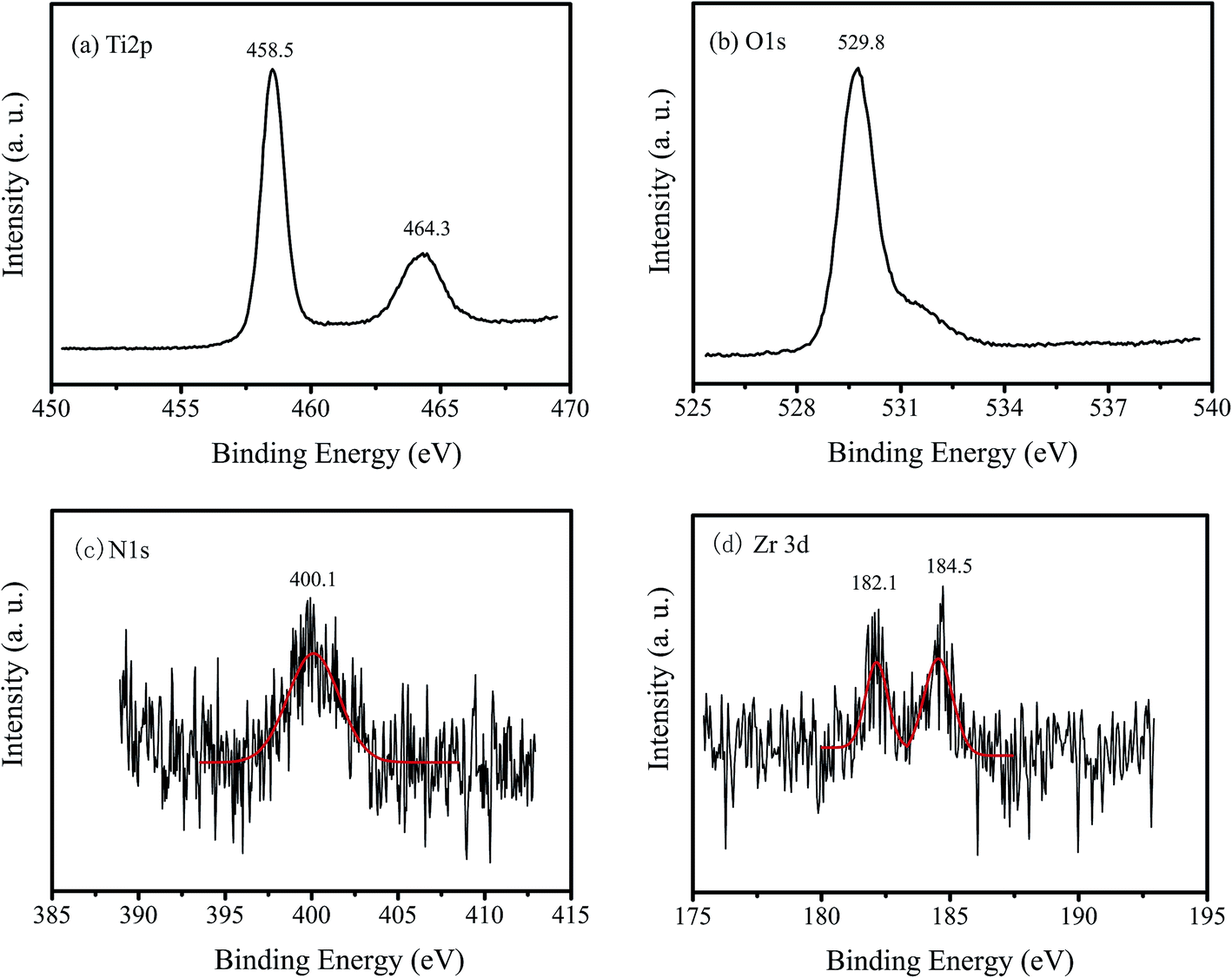 | ||
| Fig. 3 XPS spectra of 1% Zr/N–TiO2 NRs. (a) Ti 2p, (b) O 1s, (c) N 1s, and (d) Zr 3d. | ||
Fig. 4A and B show the plane-view SEM images of un-doped TiO2 and 1% Zr/N–TiO2 NRs, respectively. Fig. 4C and D show the cross sectional SEM images of un-doped TiO2 and 1% Zr/N–TiO2 NRs, respectively. The diameter and length of the un-doped TiO2 NRs were determined to be 50 ± 5 nm and 480 ± 15 nm, respectively. The diameter and length of the 1% Zr/N–TiO2 NRs were determined to be 40 ± 8 nm and 460 ± 35 nm, respectively. The diameter of N–TiO2 NRs is slightly decreased compared with that of un-doped TiO2 NRs. The length distribution of 1% Zr/N–TiO2 NRs is more ununiform than that of un-doped TiO2 NRs. This could be attributed to the effect of Zr/N doping.
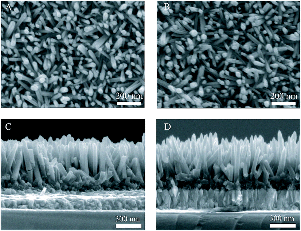 | ||
| Fig. 4 SEM images of un-doped TiO2 (A and C), and 1% Zr/N–TiO2 (B and D). | ||
Fig. 5A shows the UV-vis absorption spectra of un-doped TiO2 and 1% Zr/N–TiO2 NRs. The Zr/N–TiO2 NRs presented a stronger absorption intensity than un-doped TiO2. The energy band gap (Eg) can be determined using the Tauc plot which is shown below,26
| (αhν)1/2 = A(hν − Eg) | (1) |
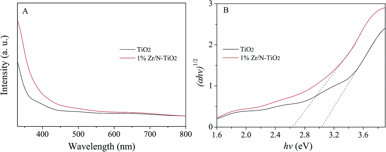 | ||
| Fig. 5 (A) UV-vis absorption spectra of un-doped TiO2 and 1% Zr/N–TiO2 NRs. (B) Tauc curves. | ||
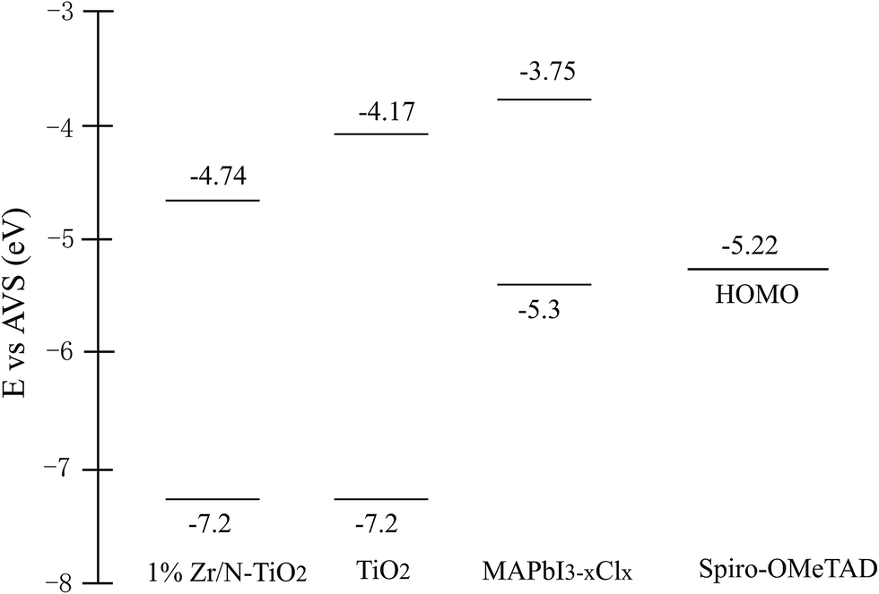 | ||
| Fig. 6 Energy band diagrams of TiO2, MAPbI3−xClx, and spiro-OMeTAD. | ||
Photoluminescence (PL) can provide an evidence of electron extraction and transfer efficiency.29,30 Therefore we measured the PL spectra of un-doped TiO2/MAPbI3−xClx and 1% Zr/N–TiO2/MAPbI3−xClx and shown in Fig. 7A. The peak at 780 nm is attributed to the emission from MAPbI3−xClx.1 The PL intensity of Zr/N–TiO2/MAPbI3−xClx is weaker than that of un-doped TiO2/MAPbI3−xClx, which demonstrated that the efficiency of electron extraction and transport of Zr/N–TiO2/MAPbI3−xClx is more than that of un-doped TiO2/MAPbI3−xClx.
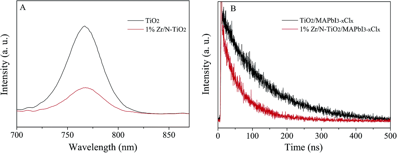 | ||
| Fig. 7 (A) PL, and (B) TRPL spectra of un-doped TiO2/MAPbI3−xClx and 1% Zr/N–TiO2/MAPbI3−xClx. | ||
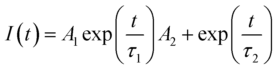
Fig. 7B displays the time-resolved photoluminescence (TRPL) kinetic decay curves of un-doped TiO2/MAPbI3−xClx and 1% Zr/N–TiO2/MAPbI3−xClx. The TRPL curve was fitted to a biexponential function,
 | (2) |
The detailed parameters are summarized in Table 2. The fast decay (τ1) might be originated from the transportation of free carriers from perovskite layer to the respective hole or electron contact. The slow decay (τ2) could be attributed to the radiative recombination of free charge carriers before the charge collection.31,32 From Table 2, we can see that the fast decay time (28.5 ns) and slow decay time (95.2 ns) of Zr/N–TiO2/MAPbI3−xClx are less than those of un-doped TiO2/MAPbI3−xClx (55.1 ns and 121.4 ns), while the fraction of fast decay process (31.3% and 43.3%) was increased. This proves the improved electron extraction and transport efficiency, and reduced charge recombination of Zr/N–TiO2 contrast to un-doped TiO2.
| Sample | τ1/ns | % of τ1 | τ2/ns | % of τ2 |
|---|---|---|---|---|
| TiO2/MAPbI3−xClx | 55.1 | 31.3 | 121.4 | 67.7 |
| 1% Zr/N–TiO2/MAPbI3−xClx | 28.5 | 43.3 | 95.2 | 56.7 |
Electrochemical impedance spectroscopy (EIS) is a powerful technique to reveal the underlying carrier transport behavior in perovskite solar cells.33,34 The Nyquist plots of solar cells based on un-doped TiO2 and 1% Zr/N–TiO2 NRs are shown in Fig. 8A, in which two RC arcs were observed. The data were fitted to an equivalent circuit shown in Fig. 8B. The high-frequency RC element is attributed to contact resistance (Rco) at the interfaces, while the low-frequency element is ascribed to the recombination resistance (Rrec) and chemical capacitance (Cμ) of the system, and the Rs is an additional contribution from series resistance.18,35 The fitting parameters are listed in Table 3. The total series resistance (Rs + Rco) for the cells based on Zr/N–TiO2 is smaller than that on un-doped TiO2, while the recombination resistance of the former is larger than that of the latter, which indicates that an enhanced charge transport ability and induced carrier recombination rate for the cells based on Zr/N–TiO2. This agrees well with the I–V measurements.
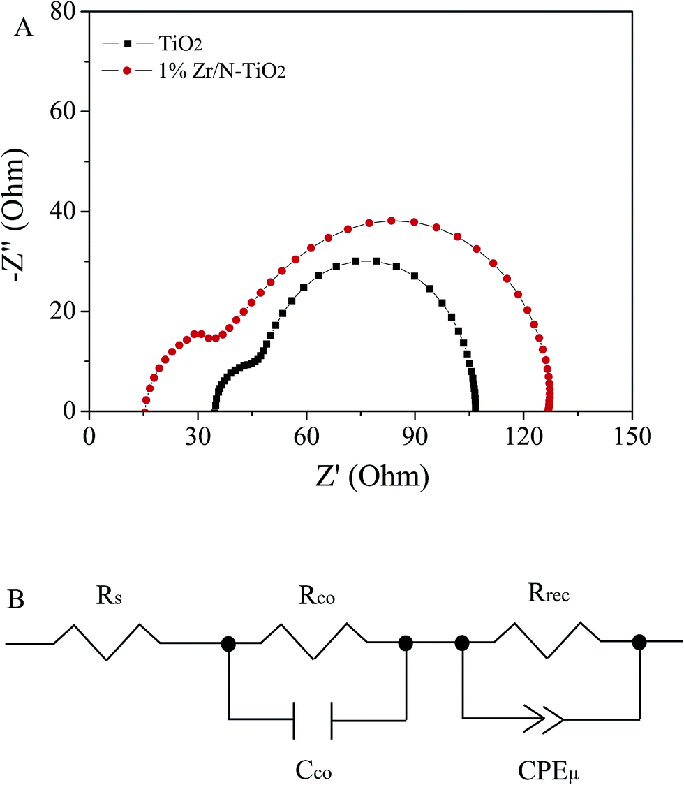 | ||
| Fig. 8 (A) EIS spectra of solar cells that based on un-doped TiO2 and 1% Zr/N–TiO2 NRs based solar cells. (B) Equivalent circuit for fitting the EIS data. | ||
| Sample | Rs/Ω | Rco/Ω | Rrec/Ω | CPE-T/F |
|---|---|---|---|---|
| TiO2 | 34.8 | 59.3 | 12.7 | 6.3 × 10⁻⁶ |
| 1% Zr/N–TiO2 | 17.4 | 22.2 | 83.1 | 4.8 × 10⁻⁵ |
4. Conclusion
In this study, Zr/N-codoped TiO2 NRs were synthesized and perovskite solar cells based on them were fabricated. The solar cells based on Zr/N–TiO2 NRs presented an enhanced performance compared with those on un-doped TiO2 NRs. The solar cell performance was optimized by changing the Zr doping contents. The PCE of solar cells based on Zr/N–TiO2 with the Zr doping content of 1% (Zr/Ti, atomic ratio) has been achieved 12.6%, which was 31.6% higher than that of solar cells based on un-doped TiO2. To explain the enhancement, some investigations were performed. EDS and Tauc plot spectra indicated the incorporation of Zr in TiO2 nanorods. Absorption spectra showed higher absorption of visible light for Zr/N–TiO2 than un-doped TiO2. The Zr doping reduced the energy band gap from 3.03 to 2.64 eV. The PL and TRPL spectra displayed the faster electron transfer from perovskite layer to Zr/N–TiO2 than to un-doped TiO2. EIS showed the smaller resistance of device based on Zr/N–TiO2 than that on un-doped TiO2.Acknowledgements
This work is supported by the NSFC-Henan Province Joint Fund (U1604144), Science Fund of Henan Province (162300410020), National Science Research Project of Education Department of Henan Province (No. 17A140005), Science and Technology Development Project of Henan Province (No. 142102210389).References
- N. Ahn, D. Y. Son, I. H. Jang, S. M. Kang, M. Choi and N. G. Park, J. Am. Chem. Soc., 2015, 137, 8696–8699 CrossRef CAS PubMed.
- D. P. McMeekin, G. Sadoughi, W. Rehman, G. E. Eperon, M. Saliba, M. T. Horantner, A. Haghighirad, N. Sakai, L. Korte, B. Rech, M. B. Johnston, L. M. Herz and H. J. Snaith, Science, 2016, 351, 151–155 CrossRef CAS PubMed.
- H. Tsai, W. Y. Nie, J. C. Blancon, C. C. Toumpos, R. Asadpour, B. Harutyunyan, A. J. Neukirch, R. Verduzco, J. J. Crochet, S. Tretiak, L. Pedesseau, J. Even, M. A. Alam, G. V. Gupta, J. Lou, P. M. Ajayan, M. J. Bedzyk, M. G. Kanatzidis and A. D. Mohite, Nature, 2016, 536, 312–316 CrossRef CAS PubMed.
- S. Michael, M. Taisuke, D. Konrad, J. Y. Seo, A. Ummadisingu, S. M. Zakeeruddin, J. P. Correa-Baena, W. R. Tress, A. Abate, A. Hagfeldt and M. Gratzel, Science, 2016, 354, 206–209 CrossRef PubMed.
- National Renewable Energy Laboratory Best Research-Cell Efficiencies, https://www.nrel.gov/ncpv/images/efficiency_chart.jpg, accessed 17 May 2016.
- K. Mahmood, B. S. Swain, A. R. Kirmani and A. Amassian, J. Mater. Chem. A, 2015, 17, 9051–9057 Search PubMed.
- J. H. Heo, S. H. Im, J. H. Noh, T. N. Mandal, C. S. Lim, J. A. Chang, Y. H. Lee, H. J. Kim, A. Sarkar, M. K. Nazeeruddin, M. Gratzel and S. I. Seok, Nat. Photonics, 2013, 7, 487–492 CrossRef.
- K. Manseki, T. Ikeya, A. Tamura, T. Ban, T. Sugiura and T. Yoshida, RSC Adv., 2014, 4, 9652–9655 RSC.
- Y. M. Li, Y. Guo and X. F. Zhou, Electrochim. Acta, 2016, 200, 29–36 CrossRef CAS.
- H. Nagaoka, F. Ma, D. W. deQuilettes, S. M. Vorpahl, M. S. Glaz, A. E. Colbert, M. E. Ziffer and D. S. Ginger, J. Phys. Chem. Lett., 2015, 6, 669–675 CrossRef CAS PubMed.
- J. W. Liu, J. Zhang, G. Q. Yue, X. W. Lu, Z. Y. Hu and Y. J. Zhu, Electrochim. Acta, 2016, 195, 143–149 CrossRef CAS.
- X. Q. Zhang, Y. P. Wu, Y. Huang, Z. H. Zhou and S. Shen, J. Alloys Compd., 2016, 681, 191–196 CrossRef CAS.
- X. J. Yao, X. D. Wang, L. Su, H. Yan and M. Yao, J. Mol. J. Mol. Catal. A: Chem., 2011, 351, 11–16 CrossRef CAS.
- R. Dhabbe, A. Kadam, P. Korake, M. Kokate, P. Waghmare and K. Garadkar, J. Mater. Sci., 2015, 26, 554–563 CAS.
- M. Zhang, X. L. Yu, D. D. Lu and J. J. Yang, Nanoscale Res. Lett., 2013, 8, 543–551 CrossRef PubMed.
- J. Y. Park, K. H. Lee, B. S. Kim, C. S. Kim, S. E. Lee, K. Okuyama, H. D. Jang and T. O. Kim, RSC Adv., 2014, 4, 9946–9953 RSC.
- Z. L. Zhang, J. F. Li, X. L. Wang, J. Q. Qin, W. J. Shi, Y. F. Liu, H. P. Gao and Y. L. Mao, Nanoscale Res. Lett., 2017, 12, 43–49 CrossRef PubMed.
- J. F. Li, Z. L. Zhang, H. P. Gao, Y. Zhang and Y. L. Mao, J. Mater. Chem. A, 2015, 3, 19476–19482 CAS.
- M. M. Lee, J. Teuscher, T. Miyasaka, T. N. Murakami and H. J. Snaith, Science, 2012, 338, 643–647 CrossRef CAS PubMed.
- P. Goswami and J. N. Gangul, Dalton Trans., 2013, 42, 14480–14490 RSC.
- H. S. Kim, J. W. Lee, N. Yantara, P. P. Boix, S. A. Kulkarni, S. Mhaisalkar, M. Gratzel and N. G. Park, Nano Lett., 2013, 13, 2412–2417 CrossRef CAS PubMed.
- F. Zhang and X. H. Liu, Thin Solid Films, 1998, 326, 171–174 CrossRef CAS.
- K. V. Buneesh, D. K. Kim and D. W. Park, Nanoscale, 2010, 2, 1222–1228 RSC.
- C. Feng, Y. Wang, J. Zhang, L. Yu, D. Li, J. Yang and Z. Zhang, Appl. Catal., B, 2012, 113, 61–71 CrossRef.
- M. Zhang, X. L. Yu, D. D. Lu and J. J. Yang, Nanoscale Res. Lett., 2013, 8, 543–550 CrossRef PubMed.
- X. Y. Liu, H. W. Zheng, Z. L. Zhang, X. S. Liu, R. Q. Wan and W. F. Zhang, J. Mater. Chem., 2011, 21, 4108–4116 RSC.
- H. S. Kim and N. G. Park, J. Phys. Chem. Lett., 2014, 5, 2927–2934 CrossRef CAS PubMed.
- Y. L. Li, W. H. Sun, W. B. Yan, S. Y. Ye, H. T. Peng, Z. W. Liu, Z. Q. Bian and C. H. Huang, Adv. Funct. Mater., 2015, 25, 4867–4873 CrossRef CAS.
- P. S. Archana, A. Gupta, M. M. Yusoff and R. Jose, Appl. Phys. Lett., 2014, 105, 53901 CrossRef.
- Y. Shi, K. Wang, Y. Du, H. Zhang, J. Gu, C. Zhu, L. Wang, W. Guo, A. Hagfeldt, N. Wang and T. Ma, Adv. Mater., 2013, 25, 4413–4419 CrossRef CAS PubMed.
- H. H. Wang, Q. Chen, H. Zhou, L. Song, S. Luo, Z. S. Louis, N. D. Marco, Y. Fang, P. Sun, T. B. Song, H. Chen and Y. Yang, J. Mater. Chem. A, 2015, 3, 9108–9115 CAS.
- D. Zhong, B. Cai, X. L. Wang, Z. Yang, Y. D. Xing, S. Miaoa, W. H. Zhang and C. Li, Nano Energy, 2015, 11, 409–418 CrossRef CAS.
- A. Dualeh, T. Moehl, N. Tetreault, J. Teuscher, P. Gao, M. K. Nazeeruddin and M. Gratzel, ACS Nano, 2013, 8, 362–373 CrossRef PubMed.
- V. Gonzalez-Pedro, E. J. Juarez-Perez, W.-S. Arsyad, E. M. Barea, F. Fabregat-Santiago, I. Mora-Sero and J. Bisquert, Nano Lett., 2014, 14, 888–893 CrossRef CAS PubMed.
- D. Y. Liu, J. L. Yang and T. L. Kelly, J. Am. Chem. Soc., 2014, 136, 17116–17122 CrossRef CAS PubMed.
| This journal is © The Royal Society of Chemistry 2017 |