
 Open Access Article
 This Open Access Article is licensed under a
 Creative Commons Attribution 3.0 Unported Licence
Enhanced anti-stocks luminescence in LaNbO4:Ln3+ (Ln3+ = Yb3+, Er3+/Ho3+/Tm3+) with abundant color†
Huining Huanga,
Haifeng Zhoub,
Juan Zhouc,
Tao Wanga,
Dapeng Huanga,
Yaqiang Wua,
Leilei Suna,
Guangjun Zhou *a,
Jie Zhana and
Jifan Hua
*a,
Jie Zhana and
Jifan Hua
aState Key Laboratory of Crystal Materials, Shenzhen Research Institute, Shandong University, Jinan 250100, P. R. China. E-mail: gjzhou@sdu.edu.cn
bSchool of Materials Science and Engineering, Qilu University of Technology, Jinan 250353, P. R. China
cCenter for Disease Prevention and Control of Jinan Military Command, Jinan 250014, P. R. China
First published on 16th March 2017
Abstract
Lanthanide ion doped up-conversion luminescent (UCL) materials, which have the ability to convert near-infrared longer wavelength excitation light into shorter wavelength visible light, have recently drawn much attention. Now, a series of Ln3+ (Yb3+, Er3+/Ho3+/Tm3+) ions doped LaNbO4 (LNO) materials were prepared through a two-step route, including a facile sol–gel process and subsequent combustion. In our work, thermogravimetric and differential thermal analysis (TG-DTA), X-ray diffraction (XRD), field emission scanning electron microscopy (FE-SEM), up-conversion luminescence (UCL), energy level diagram, luminescent lifetimes and corresponding CIE were utilized to characterize the properties. A 980 nm laser was employed to excite Yb3+ ions to achieve the 2F7/2 → 2F5/2 transition, and the LNO:Yb3+,Er3+/Ho3+/Tm3+ samples exhibited intense green, yellowish-green and blue emission, respectively. Luminescent spectra at different powers demonstrated the two-photon absorption process; meanwhile, the corresponding energy transfer mechanisms from Yb3+ to Ln3+ and the emissions of Ln3+ under 980 nm laser excitation were described via an energy level diagram. Moreover, multicolor UCL emissions, the optimal intensities and corresponding mechanism were systematically explored via a suite of concentration spectra of different Ln3+ ions. At last, the decay lifetimes based on the concentration variation of Yb3+ ion demonstrated that the lifetimes are heavily influenced by Yb3+ ion.
1. Introduction
Up-conversion luminescence (UCL), a process that can convert near-infrared excitation into visible emission, also known as anti-Stokes shift, has recently gained more and more attention.1–8 The energy transfer process, in which two or more low-energy photons are converted into one high-energy photon, has great potential applications in laser materials, data storage, near-infrared quantum counters, solar energy, traditional light, display technologies, biological imaging and so on.9–20 Multiple metastable levels of the lanthanides just perfectly meet the requirement of these applications. The lanthanides are filled with the 4f-shell which range from element lanthanum (La) to lutetium (Lu), and their trivalent ions (Ln3+) generally possess several excited 4f energy level except for La3+, Yb3+, Ce3+, and Lu3+. Because the unique 4f–4f transitions of Ln3+ are shielded by the 5s2 and 5p6 sub-shells, weak electron–phonon are coupling and consequently sharp and narrow f–f transition bands are come into being. Besides, the f–f transitions are Laporte forbidden which can lead to low transition probabilities and substantially long-lived excited states.21 Therefore, rare-earth doped up-conversion materials are extremely available for varied application.UCL can be achieved by singly doped and double doped materials. Ln3+ ions such as Er3+, Ho3+ and Tm3+, which have abundant ladder-like arranged energy levels, are usually employed as activators in the UCL materials. However, the capacity absorbing cross-sections of Ln3+ is extremely low, and in turn the UCL intensity of singly doped materials is overall low. Additionally, high doping levels can result in harmful cross-relaxation and quenching excitation energy. Therefore, it is essential to reduce the concentration of Ln3+ and avoid the quenching effect. As a consequence, a sensitizer which has an abundant absorption cross-section in the near-infrared range is usually co-doped to enhance the UCL intensity. Trivalent Yb possesses an extremely simple energy level structure, including only one ground state level and one excited state level. In addition, the excited state level of Yb3+ is higher than the metastable energy levels of the representative up-converting Ln3+ (Er3+, Ho3+, and Tm3+) and the 2F7/2 → 2F5/2 transition is perfectly resonant with them because the energy state pair of Ln3+ is closed to the energy gap of Yb3+ (104 cm−1). With the assistance of Yb3+, a relatively low (less than 0.02) content of the up-converting activators can realize the UCL emission. In the experiments, the optimal concentrations of Er3+/Ho3+/Tm3+ are 0.02, 0.005 and 0.003, respectively. In our work, the Yb3+ ions with excellent optical characteristics are employed as a sensitizer in high-efficiency UCL materials.
Beyond that, it is extremely vital to find a suitable host compound with outstanding optical properties. Firstly, ideal host materials should be inorganic compounds with trivalent rare-earth ions, which ascribe to the similar ionic size and chemical properties of the whole rare-earth ions. Secondly, ideal host materials also require low lattice phonon energy, which can reduce non-radiative loss to increase the radiative emission. Although heavy halides and fluorides exhibit low phonon energy (less than 300 cm−1 and 350 cm−1), the applications are still limited due to their hygroscopic and instability. In comparison, oxides exhibit higher thermal and chemical stability, so appropriate oxides with relatively low phonon energy have more promising application. The third influencing factor is the crystal structure, which can be imputed to the difference of the crystal-fields around activators in various symmetrical matrices. Compared with high symmetry hosts, low symmetry hosts have more probability to achieve f–f transition for up-converting Ln3+, and this is because the electronic coupling between 4f energy levels and electronic configuration. Furthermore, the reduction of cation size in the host can lead to the enhancement of the crystal-field around the doped ions and subsequently increase UCL intensity.
Up to now, a series of niobates such as YNbO4, LaNbO4, GdNbO4, CaNb2O6 have showed good mechanical and chemical stability, thus they have attracted widespread attention. Lin group have demonstrated that the niobates are a commendable host material in the down-conversion emission.22–24 La3+ possesses the biggest radius which can be replaced by the other rare-earth ions and the symmetry of LaNbO4 is pretty low, which are beneficial to enhance the optical properties, thus we select LaNbO4 as our host material.
As far as we know, as of now, the UCL properties of niobate have rarely been reported. In our work, LNO and Ln3+ doped LNO have been fabricated via a facile sol–gel and combustion method. In general, the adulteration of various rare-earth ions is the easiest way to achieve multicolor in the UCL emission. Under the irradiation of 980 nm laser, four-color emissions from UCL materials NaYbF4:Tm/Ho/Er/Yb were first demonstrated by Nann et al.25 In our work, an array of up-conversion luminescent properties, including the up-conversion mechanism, power-dependent spectra, concentration-dependent spectra, lifetimes and CIE chromaticity coordinates. Additionally, we find the optimal concentration to achieve the strongest UCL intensities. It indicates that the samples have great prospect for applications such as 3D display and solid-state lasers.
2. Experimental
2.1. Synthetic procedures
A sequence of nano/micro-materials with chemical composition of La1−(y+e/h/t)NbO4:yYb3+,eEr3+/hHo3+/tTm3+ (y = 0.02–0.25, e = 0.005–0.04, h = 0.0025–0.02, t = 0.001–0.006), where La atoms occupations were considered to be occupied by other rare earth atoms, were synthesized by a facile sol–gel combustion process. Stoichiometric amounts of high-purity chemical compounds, including lanthanum oxide (La2O3), ytterbium oxide (Yb2O3), erbium oxide (Er2O3), holmium oxide (Ho2O3), thulium oxide (Tm2O3), niobium oxide (Nb2O5), citric acid (C6H8O7·H2O) and ammonium nitrate (NH4NO3), were used as the raw materials. The synthetic method is a two-step route, involving the sol–gel progress and the high-temperature combustion progress. First, La(NO3)3, Yb(NO3)3, Ho(NO3)3 and Er(NO3)3 aqueous solutions were prepared by dissolving the calculated amount of La2O3, Yb2O3, Er2O3, Ho2O3 and Tm2O3 into diluted nitric acid at a certain mole ratio, respectively. The residual nitric acid was removed via heating and evaporation. Second, excess hydrofluoric acid (HF, 40%) was employed to dissolve niobium oxide (Nb2O5, 99.9%) at 90 °C and the pH was regulated to 9.0 by adding aqueous ammonia solution, then a white precipitate of Nb2O5·nH2O was obtained. Subsequently, the precipitate was washed with deionized water repeatedly by centrifugation to guarantee that the F− ion was entirely removed. Third, citric acid and ammonium nitrate were used to dissolve the precipitate with a mole ratio of 3![[thin space (1/6-em)]](https://www.rsc.org/images/entities/char_2009.gif) :5:1. In this process, citric acid and ammonium nitrate play the roles of complexant and fuel, respectively. Fourth, the RE nitrates were dissolved in the above solution under continuous stirring at a constant temperature of 85 °C to form the homogeneous sol. The transparent sol became a white gel with high viscosity by evaporating the water. After drying the gel for 12 h at 110 °C, a nut-brown precursor was formed. The precursor was directly annealed in air for 3 h at 1000 °C in a furnace and cooled down to room temperature naturally to obtain the final product.
:5:1. In this process, citric acid and ammonium nitrate play the roles of complexant and fuel, respectively. Fourth, the RE nitrates were dissolved in the above solution under continuous stirring at a constant temperature of 85 °C to form the homogeneous sol. The transparent sol became a white gel with high viscosity by evaporating the water. After drying the gel for 12 h at 110 °C, a nut-brown precursor was formed. The precursor was directly annealed in air for 3 h at 1000 °C in a furnace and cooled down to room temperature naturally to obtain the final product.
2.2. Characterization
Thermal analysis of the precursor was performed on a thermogravimetric-differential thermal analyser (TG-DTA) (Perkin Elmer Corporation, Diamond TG-DTA) from 30 °C to 1100 °C with a constant heating rate of 20 °C min−1. The X-ray diffraction (XRD) measurements were carried out on a Germany Bruker Axs D8-Focus diffractometer with graphite-monochromatized Cu Kα radiation (λ = 0.15418 nm) at a scanning rate of 0.04 s per step over the 2θ range from 10° to 80°. The morphology and size of the products were obtained using a scanning electron microscope (SEM, Hitachi, S-4800). The UCL spectra, decay times and were recorded on fluorescence spectrometer (Edinburgh FLS 980) equipped with a tuneable 980 nm semiconductor (1 W laser) as the excitation source.3. Results and discussion
3.1. Structural, phase and morphological analysis
The TG-DTA curves of pure LNO precursor xerogel powder dried for 12 h at 110 °C is shown in Fig. 1. Throughout the temperature range from 30 °C to 1100 °C, there are three main weight loss stages in the TG curve. The first stage is from room temperature to 235 °C. In this stage, the evaporation of water, the combustion of organic phases (such as citric acid) and the thermal decomposition of NO3− collectively result in weight loss (at approximately 40.83%), an endothermic peak (at approximately 57 °C) and a strong exothermic peak (at approximately 212 °C). At the second stage, throughout which the temperature ranges from 235 °C to 508 °C, the weight loss is about 37.65%, and a high-intensitive exothermic peak occurs at 486 °C, which can be ascribed to the further combustion of the remaining organic materials. The last stage of weight loss occurring between 508 °C and 645 °C is about 2.52%, corresponding to a faint exothermic weak at 632 °C, which is mainly because of the process of the phase transformation from tetragonal to monoclinic and higher crystallization. The tetragonal phase can not be existent under high temperature.26 No obvious weight loss is observed above 632 °C, which indicates that all organic compounds in the precursor had been decomposed completely below 632 °C, and the crystallized LNO inorganic phase is formed.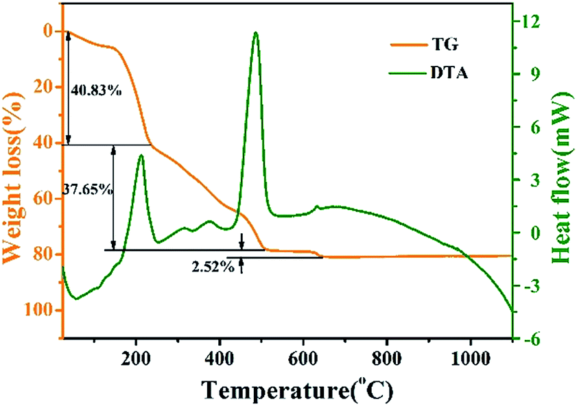 | ||
| Fig. 1 TG-DTA curves of pure LNO precursor xerogel powder. | ||
The composition, crystal structure, and phase purity of the as-prepared samples LNO host under various temperatures and times, LNO:0.10Yb3+,0.02Er3+, LNO:0.15Yb3+,0.005Ho3+ and LNO:0.15Yb3+,0.003Tm3+ are respectively determined from the XRD patterns, which are clearly shown in Fig. 2. All of the diffraction peaks could be well matched with the XRD pattern of monoclinic LaNO4 phase corresponding to standard reference JCPDS card no. 81-1973. As shown in Fig. 3, the crystallization belongs to monoclinic system, and space group is I112/b (15), and cell parameters are a = 5.5634 Å, b = 5.2030 Å, c = 11.5227 Å, V = 332.69(3) Å3, and Z = 4. Significantly, as the annealing temperature increases from 500 °C to 1000 °C and reaction time grows from 0.5 h to 3 h, the diffraction peaks become obviously stronger and sharper, implying that the high annealing temperature and longer reaction time contribute to the high crystallinity of the samples. Based on the higher crystallinity of the heat treated samples, we can choose more appropriate condition to prepare the samples. In general, the samples along with high crystallinity show higher emission intensity. Further, no traces of impurity phases are observed, demonstrating little change of this crystal structure accompanied by introducing such Yb3+, Er3+, Ho3+ and Tm3+ ions into the host. This is because such Ln3+ ions have similar radius and the La3+ ions is just located at the central position surrounded by eight oxygen atoms and the LaNbO4 phase has a low symmetry crystal structure. Only one kind of La cationic position with a Wyckoff position 4e could be taken in for activators due to the analogical ionic radius of La3+ [r = 1.061 Å, CN = 8], Yb3+ (r = 0.858 Å, CN = 8), Er3+ (r = 0.881 Å, CN = 8), Ho3+ (r = 0.894 Å, CN = 8) and Tm3+ (r = 0.87 Å, CN = 8). Furthermore, in the inset of Fig. 2, the diffraction peaks (−121) (121) are slightly shifted to a higher degree and the crystallinity lower down accompanied with Yb3+, Er3+/Ho3+/Tm3+ doped into the host material.
 | ||
| Fig. 2 XRD patterns of the as-prepared (a) LaNbO4 host with different temperature, time and the standard pattern (JCPDS 81-1973) of LaNbO4. (b) LaNbO4:0.10Yb3+,0.02Er3+, LNO:0.15Yb3+,0.005Ho3+, LNO:0.15Yb3+,0.003Tm3+ samples. | ||
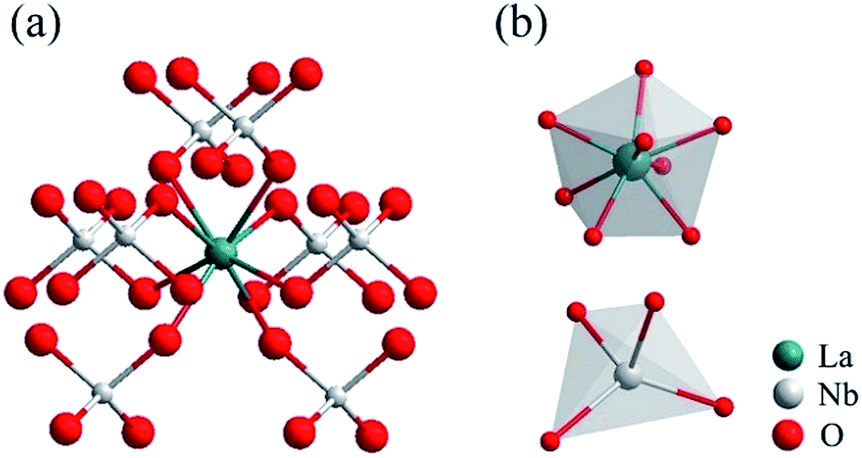 | ||
| Fig. 3 Crystal structure of the monoclinic LaNbO4 phase. | ||
The SEM images of the as-prepared LNO, LNO:0.10Yb3+,0.02Er3+, LNO:0.15Yb3+,0.005Ho3+, LNO:0.15Yb3+,0.003Tm3+ samples are shown in Fig. 4. It can be clearly found that the morphology and particle size of the as-prepared samples have been slightly influenced by the dopant, which is corresponding to the XRD patterns.
 | ||
| Fig. 4 SEM images of the as-prepared (a) LNO, (b) LNO:0.10Yb3+,0.02Er3+, (c) LNO:0.15Yb3+,0.005Ho3+, (d) LNO:0.15Yb3+,0.003Tm3+. | ||
The agglomeration of the samples is observed especially in un-doped LNO sample, which is attributed to the high-temperature combustion process. The morphology and size of the samples are not comparatively homogeneous based on the same reason. The diameter of all the samples ranges from 200 nm to 500 nm except that the morphology become more uniform along with Yb3+, Er3+, Ho3+, Tm3+ co-doped in LNO. The TEM images which shown in Fig. S1† are also demonstrated the phenomenon.
3.2. Upconversion photoluminescence properties and mechanism
In order to obtain multicolor in the UCL, Er3+, Ho3+, Tm3+ together with Yb3+ are doped in LNO, respectively. The UCL spectra of LNO:Yb3+,Er3+/Ho3+/Tm3+ under 980 nm excitation and their corresponding CIE (Commission Internationale de I'Eclairage 1931 chromaticity) coordinates positions are shown in Fig. 5. Sharp characteristic emission peaks are all obvious in the UCL spectra. Fig. 5a exhibit the UCL spectrum of the as-prepared LNO:0.10 Yb3+,0.02 Er3+ and there are mainly two typical emission bands. The shorter-wavelength (green) emission in the range of 510 to 580 nm, corresponding to the transition from the excited state 2H11/2 and 4S3/2 to the ground state 4I15/2. While the longer-wavelength (red) emission ranging from 635 to 690 nm, which belongs to 4F9/2 → 4I15/2 transition of Er3+. Because the intensity of the green emission is obviously stronger than the red emission, the final color is green and CIE chromaticity diagram for it is (0.26790, 0.71130) as shown in Fig. 5d(E) under the excitation of 980 nm laser.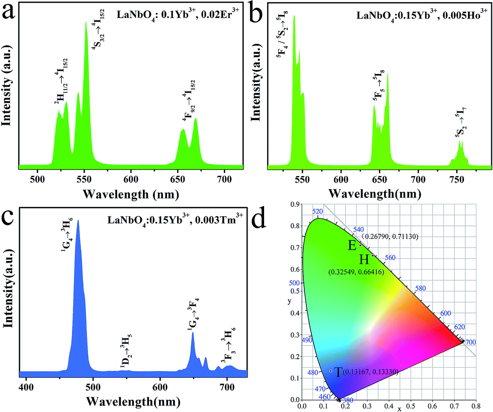 | ||
| Fig. 5 The up-conversion emission spectra of (a) LNO:0.10Yb3+,0.02Er3+, (b) LNO:0.15Yb3+,0.005Ho3+, (c) LNO:0.15Yb3+,0.003Tm3+, (d) the CIE chromaticity coordinates of the as-prepared samples under the 980 laser excitation. | ||
Fig. 5b shows the UCL spectrum of the as-prepared LNO:0.15Yb3+,0.005Ho3+, radiative relaxation processes of 5F4/5S2 → 5I8, 5F5 → 5I8 and 5S2 → 5I7 levels corresponding to green (about 540 nm), red (about 660 nm) and NIR (about 753 nm) emissions, respectively. In addition, the CIE chromaticity coordinates of LNO:0.15Yb3+,0.003Ho3+ is (0.32549, 0.66416) shown in Fig. 5d(H) under the excitation of 980 nm laser.
Fig. 5c displays the UCL spectrum of the as-prepared LNO:0.15Yb3+,0.003Tm3+, which exhibit one extremely strong blue emission, one weak green emission and two very weak red emission ascribed to 1G4 → 3H6 (located at 475 nm), 1D2 → 3H5 (between 515 nm to 560 nm) and 1G4 → 3F4, 3F3 → 3H6 (ranging from 625 nm to 720 nm) respectively. The final color is relative pure blue and CIE chromaticity diagram is (0.13167, 0.13330) as shown in Fig. 5d(T) under the excitation of 980 nm laser.
As is well-known to all, the UCL is an anti-Stokes luminescent process, in which two or more low-energy photons are consecutively absorbed and followed by emission of a higher-energy photon in quick succession.27 To explore the populating mechanism, the up-conversion luminescent properties are compared at different powers, which are shown in Fig. 6a–c. According to the spectra, the transition intensity of the as-prepared samples becomes stronger corresponding to the increasing pump powers.
 | ||
| Fig. 6 UCL spectra of the as-prepared (a) LNO:0.10Yb3+,0.02Er3+, (b) LNO:0.15Yb3+,0.005Ho3+, (c) LNO:0.15Yb3+,0.003Tm3+ under the excitation of 980 nm laser at the different power and the corresponding power dependence of UCL in (d) LNO:0.10Yb3+,0.02Er3+, (e) LNO:0.15Yb3+,0.005Ho3+, (f) LNO:0.15Yb3+,0.003Tm3+. | ||
For any unsaturated UCL process, the visible emission intensity (Iem) and the pump power P of infrared excitation resource is expressed as
| Iem ∝ Pn |
In general, three luminescence mechanism have been proved in the UCL process, and they are ground/excited state absorption (GSA/ESA), energy transfer up-conversion (ETU) and photon avalanche (PA).31 In the Fig. 6d–f, each slope of all the samples is not changed, which demonstrates PA mechanism is not involved in the UCL process. To explore the UCL populating mechanism, the typical energy level diagrams and the possible mechanism for LNO:Yb3+/Er3+, LNO:Yb3+/Ho3+, LNO:Yb3+/Tm3+ are exhibited in Fig. 7a–c. The solid, dotted and curly arrows represent the emission, energy transfer, and multi-phonon relaxation process, respectively. In the Yb3+ and Ln3+ co-doped LNO samples, Yb3+ ions absorb energy from the 980 nm laser excitation, while Er3+, Ho3+ and Tm3+ generate visible emission. First of all, the ground state 2F7/2 of two Yb3+ are promoted to the 2F5/2 by absorbing the excitation of 980 nm laser. The transition of 2F7/2 → 2F5/2 is usually resonant with the f–f transition of Er3+, Ho3+ and Tm3+, prompting the efficient energy transform from Yb3+ to these ions. For LNO:Yb3+/Er3+, the ground state 4I15/2 of Er3+ is excited to the state 4I11/2. Then under the effect of ET mechanism of Yb3+ → Er3+, the excited electrons on the level 4I11/2 are partly excited to the energy level 4F7/2. Afterwards, the electrons relax from 4F7/2 to 2H11/2, 4S3/2, generating green 2H11/2, 4S3/2 → 4I15/2 transition. In another case, if the excited electrons on the energy level 4I11/2 are relaxed to the energy level 4I13/2 accompanied by another timely ET from Yb3+ to the energy level 4I13/2 of Er3+, the energy from 4I13/2 will be transferred to 4F9/2, and subsequently return to the ground state via radiative transition, producing red 4F9/2 → 4I15/2 transition.32–35 For LNO:Yb3+/Ho3+, the mechanism is somewhat different from LNO:Yb3+/Er3+. The ground state absorption (GSA) is the phonon assisted process because the excitation energy between donor and acceptor could not match well (about 1580 cm−1) and hence there is no resonant transition. Firstly, the energy of Ho3+ ions is excited from the ground state 5I8 to the excited state 5I6 via phonon-assisted ET. Following this process, the second photon absorbed from energy level 2F5/2 of Yb3+ or the second pump photons make Ho3+ excite to the state 5F4, 5S2 and then decay to the ground state or the state 5I7, in which process green 5F4, 5S2 → 5I8 and NIR 5F4, 5S2 → 5I7 are produced. If direct multiphotons relax to the energy level from 5F4, 5S2 to 5F5, a strong red emission 5F5 → 5I8 can be generated.36,37 Non-radiative multiphoton relaxation rate also determines the efficiency of the UCL through impacting the population of the intermediate and the emitting levels. The non-radiative multiphoton relaxation rate constant is expressed as below:
| knr ∝ exp(−βΔE/hωmax) |
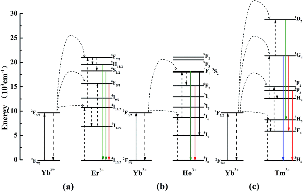 | ||
| Fig. 7 The energy level diagrams of LNO:Yb3+/Er3+, LNO:Yb3+/Ho3+, LNO:Yb3+/Tm3+ samples up-conversion mechanisms under 980 nm laser excitation. | ||
The concentration of sensitizer and activator is a significant factor of the UCL properties. The concentration affects the relative amount of Ln3+ in the samples and the average distance between adjacent dopant ions, leading to a significant impact on the optical properties of the samples. Fig. 8 exhibit various UCL spectra under 980 nm excitation for LNO:yYb3+,eEr3+/hHo3+/tTm3+ (y = 0.02–0.25, e = 0.005–0.04, h = 0.0025–0.02, t = 0.001–0.006) with different concentrations of up-conversion Ln3+ ions, respectively. All the as-prepared samples have the similar spectral profiles apart from the UCL intensity, indicating the crystal field is nearly consistent. Overall, as the concentration of Yb3+, Er3+/Ho3+/Tm3+ ions increases, the emission intensities of them in the LNO:yYb3+,eEr3+/hHo3+/tTm3+ systems are clearly rising to the maximum at y = 0.1, e = 0.02; y = 0.15, h = 0.005; y = 0.15, t = 0.003 and descending subsequently. The spectra of Er3+, Ho3+ and Tm3+ with different concentration are shown in Fig. 8a–c. When the concentrations of Er3+, Ho3+ and Tm3+ are lower than the maximum, the intensities of UCL keep rising corresponding to the increasing concentration. Energy transition is induced by the shorter distance between the activators, so the probability of energy transfers from sensitizer to activator increases.
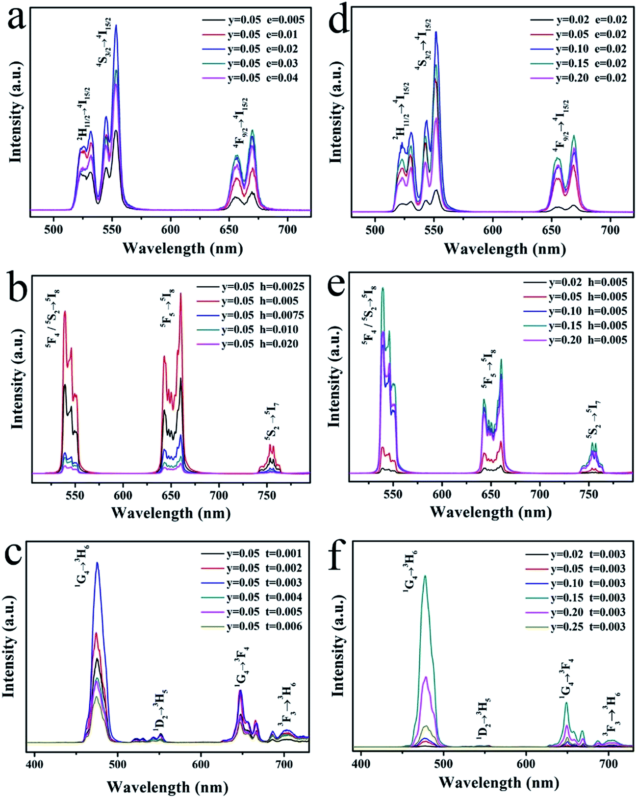 | ||
| Fig. 8 Dependence of UCL emission spectra of (a) LNO:0.05Yb3+,eEr3+, (b) LNO:0.05Yb3+,hHo3+, (c) LNO:0.05Yb3+,tTm3+, (d) LNO:yYb3+,0.02Er3+, (e) LNO:yYb3+,0.005Ho3+, (f) LNO:yYb3+,0.003Tm3+. | ||
Under the effect of cross-relaxation, the intensities decline occurs, when the concentrations surpass the optimal one. In Fig. 8d–f, as Yb3+ absorbing energy from 980 nm laser excitation, more and more energy can be absorbed and transferred to Ln3+ ions, leading to the enhancement of UCL intensities.42 However, once the concentration of Yb3+ ions exceeds the maximum, concentration quenching occurs immediately. There are two explanations to account for the phenomenon: on the one hand, the pairing or aggregation of Yb3+ ions could induce a quenching effect. On the other hand, excessive Yb3+ ions act as the energy migrating bridge to defects, which can waste the excited energy through the non-radiative energy transition from Yb3+ ions to the defects.43 The large absorption cross-section of Yb3+, which minimizes the cross-relaxation energy loss, makes the activator content is relatively low(less than 2 mol%). In addition, from the spectra of Fig. 8a and d, the green emission of quenching concentration of LNO:yYb3+,eEr3+ is not equal to the red emission, which the maximum concentrations are respectively 0.1 and 0.15. The enhancement of Yb3+ concentration leads to a relative increase in the red emission intensity of Er3+. A similar phenomenon has been found by other teams, and the factor on green emission and red emission has been studied. The reason for the variation of relative intensity of red (4F9/2 → 4I15/2) and green emission (2H11/2/4S3/2 → 4I15/2) is possibly the cross-relaxation process of 2H11/2/4S3/2 (Er) + 2F7/2 (Yb) → 4I13/2 (Er) + 2F5/2 (Yb), resulting in the population increasing on the 4F9/2 level. Compared with 4F9/2 → 4I15/2 transitions, the 2H11/2/4S3/2 → 4I15/2 are restrained by the cross-relaxation process. In consequence, the phenomenon can be attributed to back-energy transition from Er3+ to Yb3+.44–46
The corresponding CIE coordinates positions as well as the chromaticity coordinates for the as-prepared LNO:yYb3+,eEr3+/hHo3+/tTm3+ samples under 980 nm laser excitation are shown in Fig. 9 and Table 1, respectively. It can be found that the emitted light of LNO:yYb3+,Er3+ samples shift from shorter wavelength to longer wavelength accompanied with increasing value of y, which exactly demonstrates the back-energy transition from Er3+ to Yb3+. In addition, the chromaticity coordinates generally move regularly. When the ratio of Yb3+/Ho3+ increases, the CIE positions shift from light yellow to green. It may be caused by the concentration of Yb3+. For LNO:yYb3+/tTm3+, T1(LNO:0.02Yb3+,0.003Tm3+), T2(LNO:0.05Yb3+,0.003Tm3+) are respectively situated at (0.21049, 0.36642), (0.16614, 0.25068) corresponding to cyan and light blue and T3–T14 are assembled around dark blue area. Thus we can achieve different color through controlling the relative concentrations of sensitizer and activators.
 | ||
| Fig. 9 CIE chromaticity diagram for LNO:yYb3+,eEr3+(E1–E10), LNO:yYb3+,hHo3+(H1–H10), LNO:yYb3+,tTm3+(T1–T14) (y = 0.02–0.25, e = 0.005–0.04, h = 0.0025–0.02, t = 0.001–0.006). | ||
| No. of points | LNO:yYb3+,0.02Er3+ | CIE(x, y) | |
|---|---|---|---|
| E1 | y = 0.02 | e = 0.02 | (0.26514, 0.71330) |
| E2 | y = 0.05 | e = 0.02 | (0.26473, 0.71428) |
| E3 | y = 0.10 | e = 0.02 | (0.26790, 0.71130) |
| E4 | y = 0.15 | e = 0.02 | (0.26973, 0.70855) |
| E5 | y = 0.20 | e = 0.02 | (0.28336, 0.69640) |
| No. of points | LNO:0.05Yb3+,eEr3+ | CIE(x, y) | |
|---|---|---|---|
| E6 | y = 0.05 | e = 0.005 | (0.26614, 0.71319) |
| E7 | y = 0.05 | e = 0.01 | (0.27386, 0.70567) |
| E8 | y = 0.05 | e = 0.02 | (0.28428, 0.68682) |
| E9 | y = 0.05 | e = 0.03 | (0.29076, 0.69105) |
| E10 | y = 0.05 | e = 0.04 | (0.29964, 0.68363) |
| No. of points | LNO:yYb3+,0.05Ho3+ | CIE(x, y) | |
|---|---|---|---|
| H1 | y = 0.02 | h = 0.05 | (0.39424, 0.59712) |
| H2 | y = 0.05 | h = 0.05 | (0.37109, 0.61964) |
| H3 | y = 0.10 | h = 0.05 | (0.33925, 0.65076) |
| H4 | y = 0.15 | h = 0.05 | (0.32549, 0.66416) |
| H5 | y = 0.20 | h = 0.05 | (0.32951, 0.66023) |
| No. of points | LNO:0.05Yb3+,hHo3+ | CIE(x, y) | |
|---|---|---|---|
| H6 | y = 0.05 | h = 0.0025 | (0.36330, 0.62725) |
| H7 | y = 0.05 | h = 0.005 | (0.36480, 0.62580) |
| H8 | y = 0.05 | h = 0.0075 | (0.40780, 0.58411) |
| H9 | y = 0.05 | h = 0.01 | (0.36171, 0.62881) |
| H10 | y = 0.05 | h = 0.02 | (0.37292, 0.61810) |
| No. of points | LNO:yYb3+,0.003Tm3+ | CIE(x, y) | |
|---|---|---|---|
| T1 | y = 0.02 | t = 0.003 | (0.21049, 0.36642) |
| T2 | y = 0.05 | t = 0.003 | (0.16614, 0.25068) |
| T3 | y = 0.10 | t = 0.003 | (0.16215, 0.14648) |
| T4 | y = 0.15 | t = 0.003 | (0.13167, 0.13330) |
| T5 | y = 0.20 | t = 0.003 | (0.13410, 0.13978) |
| T6 | y = 0.25 | t = 0.003 | (0.14384, 0.14477) |
| T7 | y = 0.30 | t = 0.003 | (0.13575, 0.14112) |
| T8 | y = 0.35 | t = 0.003 | (0.13235, 0.13685) |
| No. of points | LNO:0.05Yb3+,tTm3+ | CIE(x, y) | |
|---|---|---|---|
| T9 | y = 0.05 | t = 0.001 | (0.15857, 0.16977) |
| T10 | y = 0.05 | t = 0.002 | (0.17098, 0.14516) |
| T11 | y = 0.05 | t = 0.003 | (0.14840, 0.13937) |
| T12 | y = 0.05 | t = 0.004 | (0.16342, 0.15238) |
| T13 | y = 0.05 | t = 0.005 | (0.16899, 0.13647) |
| T14 | y = 0.05 | t = 0.006 | (0.17106, 0.14151) |
To elucidate the quenching effect, we studied lifetimes of LNO:yYb3+,0.02Er3+ (monitored at 552 nm and 669 nm for 4S3/2 → 4I15/2 and 4F9/2 → 4I15/2), LNO:yYb3+,0.005Ho3+ (monitored at 539 nm and 660 nm for 5F4/5S2 → 5I8 and 5F5 → 5I8) and LNO:yYb3+,0.003Tm3+ (monitored at 477 nm and 649 nm for 1G4 → 3H6 and 1G4 → 3F4) under the excitation of a 980 nm laser as shown in Fig. 10. The decay curves of characteristic emissions are obviously changed with the concentration variation of Yb3+. Generally, double-exponential decay behavior of the activators is usually accompanied with the energy transition from sensitizer to activator. Thus all of the samples can be well fitted with the double-exponential formula as follows:
| I(τ) = I1exp(−t/τ1) + I2exp(−t/τ2) |
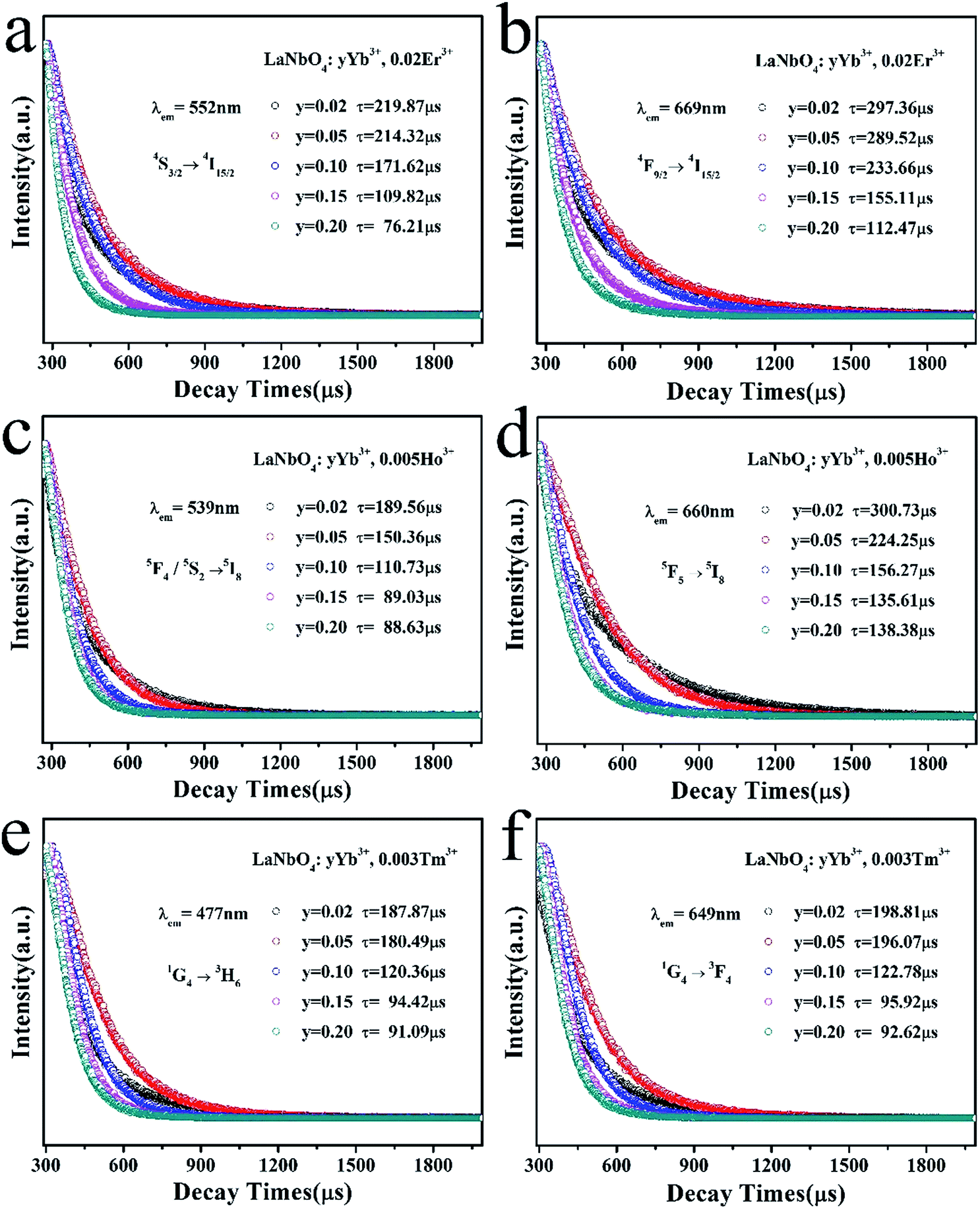 | ||
| Fig. 10 Dependence of UCL decay lifetimes of (a and b) LNO:yYb3+,0.02Er3+ monitored at 552 nm and 669 nm, (c and d) LNO:yYb3+,0.005Ho3+ monitored at 539 nm and 660 nm, (e and f) LNO:yYb3+,0.003Tm3+ monitored at 477 nm and 649 nm, respectively. | ||
4. Conclusions
In summary, a series of Ln3+ (Yb3+, Er3+/Ho3+/Tm3+) ions doped LNO materials have been successfully prepared through a facile sol–gel process and subsequent combustion, and the up-conversion results are presented. The results of TG-DTA, XRD and SEM analyses demonstrate that the samples annealed at 1000 °C present as the monoclinic phase of LNO with no additional phases and exhibit homogeneous and spherical grains. Under 980 nm laser excitation, LNO:Yb3+/Er3+, LNO:Yb3+/Ho3+, LNO:Yb3+/Tm3+ samples exhibit intense up-conversion emissions. The power-dependent UCL spectra of LNO:Yb3+,Er3+/Ho3+/Tm3+ indicate a two-photon absorption is the main process. The corresponding mechanism, including the emission, energy transfer, multi-phonon relaxation process, has been discussed detailedly. UCL multicolor fine-tuning can be achieved via changing the concentration of the dopant ions. We also receive the optimal UCL intensity, which are separately LNO:0.10Yb3+/0.02Er3+, LNO:0.15Yb3+/0.005Ho3+, LNO:0.15Yb3+/0.003Tm3+, respectively.The relative variation of red and green emission for LNO:yYb3+/eEr3+ has also given detailed explanation. And meanwhile, spectra, emitting colors as well as lifetimes have been certified the relation with the concentration of Yb3+ ion. All in all, it can be concluded that we have found an excellent matrix to achieve efficient UCL emission. The UCL properties have shown potential application in the field of 3D display and solid-state lasers and provided a new insight to design a novel UCL materials with high efficiency.
Acknowledgements
The authors would like to acknowledge the financial support from National Science Foundation of Shandong Province (ZR2016EMM20, ZR2016EMQ09), the Science and Technology Foundation of Shenzhen, Shenzhen Science and Technology Innovation Committee (JCYJ20160331173823401) and National Science Foundation of China (51372138).Notes and references
- M. Haase and H. Schäfer, Angew. Chem., Int. Ed., 2011, 50, 5808 CrossRef CAS PubMed.
- X. Teng, Y. Zhu, W. Wei, S. Wang, J. Huang, R. Naccache, W. Hu, A. Y. Tok, Y. Han, Q. Zhang, Q. Fan, W. Huang, J. A. Capobianco and L. Huang, J. Am. Chem. Soc., 2012, 134, 8340 CrossRef CAS PubMed.
- M. Challenor, P. Gong, D. Lorenser, M. Fitzgerald, S. Dunlop, D. D. Sampson and K. S. Iyer, ACS Appl. Mater. Interfaces, 2013, 5, 7875 CAS.
- Q. C. Sun, H. Mundoor, J. C. Ribot, V. Singh, I. I. Smalyukh and P. Nagpal, Nano Lett., 2013, 14, 101 CrossRef PubMed.
- J. H. Kim and J. H. Kim, ACS Photonics, 2015, 2, 633 CrossRef CAS.
- S. Guo, X. Xie, L. Huang and W. Huang, ACS Appl. Mater. Interfaces, 2015, 8, 847 Search PubMed.
- K. Yamamoto, M. Fujii, S. Sowa, K. Imakita and K. Aoki, J. Phys. Chem. C, 2015, 119, 1175 CAS.
- X. Chen, W. Xu, H. Song, C. Chen, H. Xia, Y. Zhu, D. Zhou, S. Cui, Q. Dai and J. Zhang, ACS Appl. Mater. Interfaces, 2016, 8, 9071 CAS.
- T. Liu, X. Bai, C. Miao, Q. Dai, W. Xu, Y. Yu, Q. Chen and H. Song, J. Phys. Chem. C, 2014, 118, 3258 CAS.
- A. Stepuk, G. Casola, C. M. Schumacher, K. W. Krämer and W. J. Stark, Chem. Mater., 2014, 26, 2015 CrossRef CAS.
- X. Ma and X. Ni, J. Nanopart. Res., 2013, 15, 1 CrossRef.
- J. Yu, Y. Yang, R. Fan, D. Liu, L. Wei, S. Chen, L. Li, B. Yang and W. Cao, Inorg. Chem., 2014, 53, 8045 CrossRef CAS PubMed.
- J. Jin, Y. J. Gu, C. W. Y. Man, J. Cheng, Z. Xu, Y. Zhang, H. Wang, V. H. Y. Lee, S. H. Cheng and W. T. Wong, ACS Nano, 2011, 5, 7838 CrossRef CAS PubMed.
- R. Wei, Z. Wei, L. Sun, J. Z. Zhang, J. Liu, X. Ge and L. Shi, ACS Appl. Mater. Interfaces, 2015, 8, 400 Search PubMed.
- V. Muhr, S. Wilhelm, T. Hirsch and O. S. Wolfbeis, Acc. Chem. Res., 2014, 47, 3481 CrossRef CAS PubMed.
- X. Yu, M. Li, M. Xie, L. Chen, Y. Li and Q. Wang, Nano Res., 2010, 3, 51 CrossRef CAS.
- S. M. Ametamey, M. Honer and P. A. Schubiger, Chem. Rev., 2008, 108, 1501 CrossRef CAS PubMed.
- T. V. Esipova, X. Ye, J. E. Collins, S. Sakadžić, E. T. Mandeville, C. B. Murray and S. A. Vinogradov, Proc. Natl. Acad. Sci. U. S. A., 2012, 109, 20826 CrossRef CAS PubMed.
- D. Patel, A. Kell, B. Simard, B. Xiang, H. Y. Lin and G. Tian, Biomaterials, 2011, 32, 1167 CrossRef CAS PubMed.
- X. Ge, L. Dong, L. Sun, Z. Song, R. Wei, L. Shi and H. Chen, Nanoscale, 2015, 7, 7206 RSC.
- F. Auzel, Chem. Rev., 2004, 104, 139 CrossRef CAS PubMed.
- Y. Lu, X. Tang, L. Yan, K. Li and X. Liu, J. Phys. Chem. C, 2013, 117, 21972 CAS.
- K. Li, Y. Zhang, X. Li, M. Shang, H. Lian and J. Lin, Phys. Chem. Chem. Phys., 2015, 17, 4283 RSC.
- K. Li, X. Liu, Y. Zhang, X. Li, H. Lian and J. Lin, Inorg. Chem., 2014, 54, 323 CrossRef PubMed.
- O. Ehlert, R. Thomann, M. Darbandi and T. Nann, ACS Nano, 2008, 2, 120 CrossRef CAS PubMed.
- G. Blasse and L. H. Brixner, Chem. Phys. Lett., 1990, 173, 409 CrossRef CAS.
- F. Auzel, Chem. Rev., 2004, 104, 139 CrossRef CAS PubMed.
- J. Zhao, Y. Sun, X. Kong, L. Tian, Y. Wang, L. Tu, J. Zhao and H. Zhang, J. Phys. Chem. B, 2008, 112, 15666 CrossRef CAS PubMed.
- F. Vetrone, V. Mahalingam and J. A. Capobianco, Chem. Mater., 2009, 21, 1847 CrossRef CAS.
- R. Balakrishnaiah, D. W. Kim, S. S. Yi, K. Jang, H. S. Lee and J. H. Jeong, Opt. Mater., 2009, 31, 959 CrossRef CAS.
- F. Wang and X. Liu, Chem. Soc. Rev., 2009, 38, 976 RSC.
- J. Tang, L. Chen, J. Li, Z. Wang, J. Zhang, L. Zhang, Y. Luo and X. Wang, Nanoscale, 2015, 7, 14752 RSC.
- Y. Tian, Y. Tian, P. Huang, L. Wang, Q. Shi and C. Cui, Chem. Eng. J., 2016, 297, 26 CrossRef CAS.
- F. Zhang, G. Li, W. Zhang and Y. L. Yan, Inorg. Chem., 2015, 54, 7325 CrossRef CAS PubMed.
- W. Yao, Q. Tian, J. Liu, Z. Wu, S. Cui, J. Ding, Z. Dai and W. Wu, J. Mater. Chem. C, 2016, 4, 6327 RSC.
- P. Anurag, K. Vinod, R. E. Kroon and H. C. Swart, J. Alloys Compd., 2016, 672, 190 CrossRef.
- A. Dwivedi, A. K. Singh and S. B. Rai, Dalton Trans., 2014, 43, 15906 RSC.
- J. M. F. Van Dijk and M. F. H. Schuurmans, J. Chem. Phys., 1983, 78, 5317 CrossRef CAS.
- M. Rathaiah, P. Haritha, A. D. Lozano-Gorrín, P. Babu, C. K. Jayasankar, U. R. Rodríguez-Mendoza, V. Lavín and V. Venkatramu, Phys. Chem. Chem. Phys., 2016, 18, 14720 RSC.
- H. Guo, N. Dong, M. Yin, W. Zhang, L. Lou and S. Xia, J. Phys. Chem. B, 2004, 108, 19205 CrossRef CAS.
- M. Li, X. Liu, L. Liu, B. Ma, B. Li, X. Zhao, W. Tong and X. Wang, Inorg. Chem., 2016, 3, 1082 CAS.
- D. Xu, C. Liu, J. Yan, S. Yang and Y. Zhang, J. Phys. Chem. C, 2015, 119, 6852 CAS.
- J. Wang, R. Deng, M. A. MacDonald, B. Chen, J. Yuan, F. Wang, D. Chi, T. S. A. Hor, P. Zhang, G. Liu, Y. Han and X. Liu, Nat. Mater., 2014, 13, 157 CrossRef CAS PubMed.
- G. Chen, G. Somesfalean, Y. Liu, Z. Zhang, Q. Sun and F. Wang, Phys. Rev. B: Condens. Matter Mater. Phys., 2007, 75, 195204 CrossRef.
- D. Xu, C. Liu, J. Yan, S. Yang and Y. Zhang, J. Phys. Chem. C, 2015, 119, 6852 CAS.
- A. Li, D. Xu, Y. Zhang, H. Lin, S. Yang, Z. Chen and Y. Shao, J. Am. Ceram. Soc., 2016, 99, 1657 CrossRef CAS.
Footnote |
| † Electronic supplementary information (ESI) available. See DOI: 10.1039/c6ra28592a |
| This journal is © The Royal Society of Chemistry 2017 |