DOI:
10.1039/C6RA28503A
(Paper)
RSC Adv., 2017,
7, 23355-23362
A novel h-BN–RGO hybrids for epoxy resin composites achieving enhanced high thermal conductivity and energy density
Received
21st December 2016
, Accepted 27th March 2017
First published on 27th April 2017
Abstract
In recent decades, significant attention has been focused on developing composite materials with high thermal conductivity utilizing h-BN, which has outstanding thermal conductivity. However, the enhancement in thermal conductivity by using h-BN is commonly limited because of high thermal resistance between h-BN and polymer materials. Herein, we fabricated novel h-BN–RGO hybrids (h-BN–RGO), by electrostatic assembly between h-BN and GO. It is found that the addition of h-BN–RGO hybrids into epoxy resins can enhance the thermal conductivity. The samples containing 26.04 vol% h-BN–RGO exhibit the highest thermal conductivity (3.45 W m−1 K−1), which is as high as 16 times that of neat epoxy resin (0.24 W m−1 K−1). The epoxy resins/h-BN–RGO composites also exhibit an enhanced dielectric constant (11.12) and low loss tangents (0.05). The energy density of the composites reaches 0.51 J cm−3 in the composites with 26.04 vol%, which is 79.6% higher than that of the pure epoxy. We attribute the enhanced thermal conductivity to the well-designed h-BN–RGO interface as well as the good dispersion of BN–RGO hybrids in epoxy resin. The energy density is mainly due to the absorbed effect of RGO nanosheets at the BN surface and its good dispersion in comparison with pure BN. This work offers a new insight into the methods for the improvement of thermal conductivity and energy storage characteristics, which has potential applications in integrated circuit packaging and structural energy storage.
1. Introduction
Epoxy resins are used for electrical appliances and structural plastic materials due to their excellent physical and chemical properties.1 With the development of increasing power densities in electronics, efficient thermal management has played an important role. However, epoxy resin has a low thermal conductivity of 0.2 W m−1 K−1, which cannot meet the requirement of thermal management. One of the effective ways to enhance the thermal conductivity of epoxy matrix is introducing inorganic fillers with high thermal conductivity.2–12 Among inorganic fillers, electrically conductive fillers such as graphite platelet,13 carbon nanotubes,14 and graphene sheets15 have been widely used to dissipate the heat which electronic devices generate. However, those fillers would change the insulating properties of the composites and cannot be suitable for fabricating high thermally conductive composites.
In recent years, h-BN, which is known as a two-dimensional nanomaterial, has attracted more and more attention because of their many exceptional properties, particularly high thermal conductivity.16 Traditionally, in order to reach the target thermal conductivity values (>1 W m−1 K−1), high loadings of thermal conducive fillers (50–80 vol%) in polymers are indispensable.17 However, high loadings of fillers lead to heavyweight and expensive composites with inferior mechanical properties, which limits their potential in modern electronics. On the other hand, the enhancement in thermal conductivity by using h-BN as fillers is commonly limited because of high thermal resistance between h-BN and polymer materials.18
Apart from thermal conductivity, the dielectric properties of composites such as dielectric constant, dielectric loss, breakdown strength, and energy density are also important for practical application.19 It has been accepted that the interface between the fillers and the polymer matrix is one of the most critical issues in the energy storage composites.20 At the same time, the surface modification could improve the dispersion of the fillers in the polymer matrix, which can enhance the energy density and energy efficiency of the composites. Herein, it is necessary to investigate the energy storage characteristics of the composites.
In our previous work, we fabricated boron nitride–graphene oxide hybrids and studied the effect of these hybrids on the thermal conductivity of epoxy resins. Herein, the boron nitride–graphene oxide hybrids were reduced to boron nitride–reduced graphene oxide hybrids.21 Considering the reduced graphene oxide has higher thermal conductivity than that of graphene oxide, we expect the addition of boron nitride–reduced graphene oxide hybrids will further enhance the thermal conductivity of epoxy. In addition, it was reported that the RGO can improve the dispersion of the filler in epoxy resins and reduce the agglomeration and voids.22 The h-BN–RGO/epoxy exhibited improved thermal conductivity, dielectric constant, breakdown strength and energy density. The thermal conductivity increased as the volume fraction of filler increased, and reached a maximum of 3.45 W m−1 K−1 when the loading of h-BN–RGO hybrids was 26.04 vol%. Meanwhile, the energy density storage of the composites was increased to 0.51 J cm−3, which is 61.9% higher than that of the neat epoxy matrix at the electric field of 1000 kV cm−1. Therefore, this hybrid is suitable for a wide spectrum of thermal management and energy storage applications.
2. Experimental
Materials
The h-BN powders (∼2 μm, purity > 99%) were purchased from Denka Co., Ltd (Japan). Epoxy resins (epoxy equivalent weight: 165–175 g per equiv.) were provided by Dow Co., Ltd. Graphene oxide nanosheets (GO) was provided by Shanxi Institute of Coal Chemistry (Shanxi, China). Both curing agent and catalyst were obtained from Sigma-Aldrich. Hydrazine hydrate (H4N2·H2O) was obtained from Ling Feng Chemical Co, Ltd (Shanghai, China). 3-Aminopropyltriethoxysilane (APTES) was provided by J&K Scientific Co, Ltd (Beijing, China).
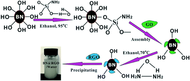
Preparation of h-BN–RGO
In a typical preparation, 10 g of h-BN powders, 190 mL of ethanol and 10 mL of H2O were stirred in a flask and ultrasonicated for 30 min. APTES (1 g) was then slowly added into the solution, which refluxed at 95 °C for 36 h under a nitrogen atmosphere. After filtering and washing three times with deionized water, the solution was dried at 70 °C under vacuum. The functionalized h-BN (5 g) was added into the GO solution (100 mL) and they were then mild stirred for 2 h. The solution was stirred at 70 °C for 5 h, after 1 mL of hydrazine hydrate (80%) was added into it.
Preparation of h-BN–RGO/epoxy composites
Epoxy resins (cycloaliphatic epoxy; 3,4-epoxycyclohexylmethyl), curing agent (hexahydrophthalic anhydride) and catalyst (imidazole) with weight ratio of 100![[thin space (1/6-em)]](https://www.rsc.org/images/entities/char_2009.gif) :100:1 was mixed together firstly. The h-BN–RGO hybrids was then added into the epoxy mixture, and mixed to get the uniform mixture. Finally, the mixture was softly poured into the mold, cured at 100 °C for 3 h, and 120 °C for 1.5 h.
:100:1 was mixed together firstly. The h-BN–RGO hybrids was then added into the epoxy mixture, and mixed to get the uniform mixture. Finally, the mixture was softly poured into the mold, cured at 100 °C for 3 h, and 120 °C for 1.5 h.
Characterization
The morphology of h-BN–RGO particles was investigated by the transmission electron microscopy (TEM) using TEM-G2F30. For TEM measurements, samples were obtained by drop casting onto a grid of carbon and copper followed by solvent evaporation in air at 70 °C. Atomic force microscopy (AFM) image of GO nanosheets was obtained in the tapping mode by using a Bruker Multimode 8 apparatus. The sample was prepared by dropping onto a silicon substrate and dried at 60 °C after it was dispersed in ethanol for 1.5 h in an ultrasonic bath. Wide-angle X-ray diffraction (XRD) was carried out with Shimadzu XRD-6000 using Cu Kα radiation at an accelerated voltage of 40 kV and a current of 30 mA. Fourier-transform infrared (FTIR) spectra were recorded on a Bruker Vertex 70 spectrometer at room temperature over a frequency range of 4000–500 cm−1. Raman spectrum is obtained over the range 1000–2000 cm−1 using Renishaw Invia Raman Microscope. The fracture morphology of h-BN–RGO/epoxy composites was observed using a Zeiss, Supra 55 field-emission scanning electron microscope (SEM). The thermal conductivity (λ) is described as the following equation:where ρ is the density of the samples, CP is the specific heat capacity, and D is the thermal diffusivity. D of composites was measured by a non-contact laser flash method (LFA-467, Netzsch). The samples for the test were sprayed with a very thin layer of graphite powder at two sides, which were 12 mm in diameter and 1 mm in thickness. The values of CP were measured by DSC (Q20, TA instruments). The dielectric properties of the composites were recorded on an impedance analyzer (Agilent 4294A), and all the measurements were carried out in the frequency range of 103 to 106 Hz. The direct current breakdown strength (BDS) was tested using an Allwin dielectric strength tester (CS9912BX, Allwin Instrument Science and Technology co. Ltd, China). Electric displacement–electric field (D–E) loops and leakage current measurements were investigated using a Precision multiferroic materials analyzer equipped with a Precision 10 kV single-channel high-voltage interface (Radiant Technology, Albuquerque, USA) and a high-voltage power amplifier (model 609B, Terk, Lockport, USA). The measurements were carried out in a silicone oil bath to avoid electrical discharges that could happen in air. Zeta potentials of functionalized h-BN and GO were measured with a Malvern Zetasizer (Nano ZS 90).
3. Results and discussion
Characterization of h-BN–RGO hybrids
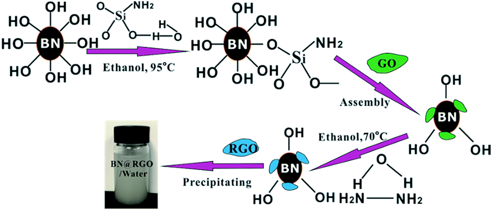
The h-BN–RGO hybrids were obtained from the chemical reduction of the electrostatically assembled h-BN–GO particles, as schematically shown in Fig. 1. The surface charge state of h-BN was switched to positive after the functionalization of amination, which will make h-BN have the ability to assemble with negative GO.21 Both functionalized h-BN and GO can disperse well in water due to the hydrophilic groups. After the solution of h-BN and GO was mixed, the particles settled down to the bottom of beaker and turn from white to brown. This phenomenon indicated that the h-BN–GO hybrid was synthesized. The phenomenon is attributed to the opposite zeta potential. The zeta potential of the functionalized h-BN is 30.4 mV, while it is −26.7 mV for GO. After reduction using hydrazine hydrate, we can obtain the h-BN–RGO hybrids.
 |
| | Fig. 1 Schematic synthesis process of h-BN–RGO hybrids. | |
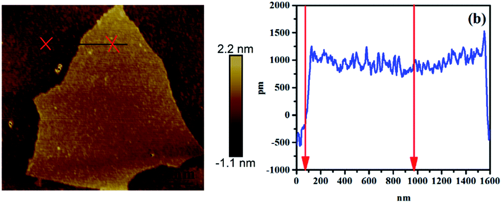
To observe the morphology and measure the thickness of RGO, AFM measurements were conducted, as shown in Fig. 2. The thickness of RGO sheets is 2 nm, which confirms the single layer of RGO sheet.
 |
| | Fig. 2 AFM image and height profiles of RGO. | |
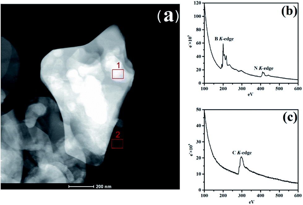
To identify h-BN and RGO, the electronic properties of the vertically stacked of h-BN–RGO particles was investigated by electron energy-loss spectroscopy (EELS) using TEM-G2F30. Fig. 3(a) illustrates the TEM image of h-BN–RGO particles, which shows that the h-BN and RGO are electrostatically attached. Fig. 4(b) and (c) are EEL spectra from areas 1 and 2 in Fig. 3(a), respectively. In Fig. 3(b), the spectra are essentially identical, exhibiting two main peaks at the energy-loss levels of about 190 eV and 405 eV. The spectrum in Fig. 3(c) shows only one peak at the energy-loss levels of about 285 eV. All the peaks of the B, N and C–K edge have been reported in the literature.23 Therefore, the h-BN–RGO particles have been prepared successfully.
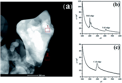 |
| | Fig. 3 (a) TEM image of h-BN–RGO, (b) core-less EEL spectrum of area 1 in (a); signals from BN from h-BN heterostructure, and (c) core-less EEL spectrum of area 2 in (a); which contains only C atoms. | |
 |
| | Fig. 4 Raman spectra of h-BN, GO, RGO and h-BN–RGO. | |
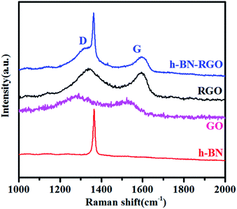
Raman spectroscopy is the fastest and non-destructive way to characterize structural damage in various carbon materials.24 Fig. 4 compares the Raman spectra of h-BN, GO, RGO and h-BN–RGO. It is observed that only an intense and sharp peak at 1368 cm−1 in the spectrum of h-BN–RGO, which is close to the characteristic Raman peak of bulk h-BN materials.25 This peak should be attributed to the high frequency intralayer E2g vibration mode of h-BN, which is in a good agreement with the previous reports.26 It is clear that RGO shows G band at 1586 cm−1, characteristic of C sp2 in-plane vibration, and D band at 1352 cm−1, characteristic of the defect carbon structure.27 The spectra of h-BN–RGO hybrids exhibits two strong peaks at 1344 and 1589 cm−1, which indicates the presence of RGO sheets in the hybrids. The intensity ratio of D to G band (ID/IG) is used to illustrate the amount of sp3-hybridized C atoms in the sp2 conjugated graphene.28 ID/IG increases from 0.82 (GO) to 0.89 (h-BN–RGO), proving the decrease of the sp2 in-plane domain induced by the introduction of defects and disorder of the sp2 domain.29
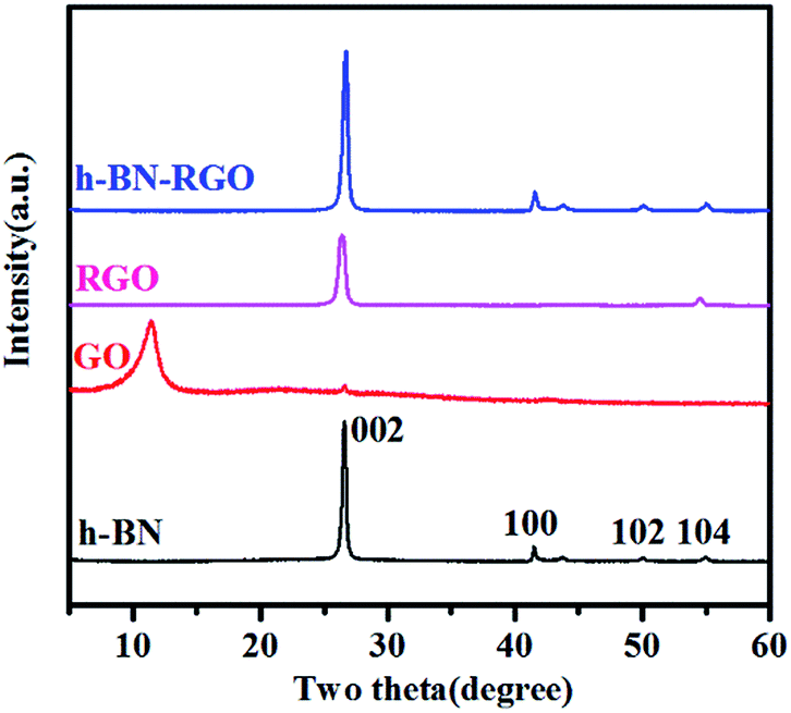
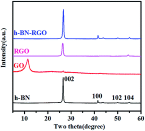
XRD patterns of h-BN, GO, RGO and h-BN–RGO are illustrated in Fig. 5. All the peaks of h-BN are consistent with the standard h-BN peaks (JCPDS: 34-0421). Apparently, the surface modification did not change the crystal structure of h-BN. As shown in Fig. 5, RGO shows a sharp diffraction peak 26.6°, corresponding to the graphitic face, while GO exhibits a broad diffraction peak at 11.3°. Abundant amounts of the functional groups on the surface of GO were removed during the chemical treatment to obtain RGO, as shown in Fig. 5. The absence of significant diffraction peak in the XRD pattern of h-BN–RGO proves the exfoliated feature after the chemical reduction of GO.
 |
| | Fig. 5 XRD patterns of h-BN, GO, RGO and h-BN–RGO. | |
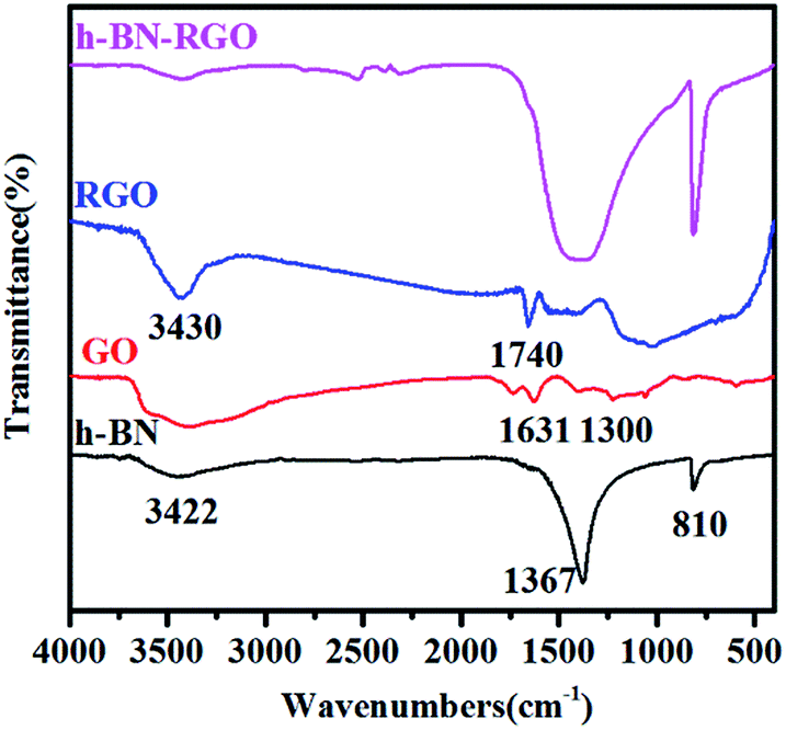
Fig. 6 presents the typical FT-IR spectra of h-BN, GO, RGO and h-BN–GO. Two strong characteristic absorption bands of h-BN can be clearly identified. The peak at 1367 cm−1 is the B–N stretching vibration and the peak around 810 cm−1 can be attributed to the B–N–B out-of-plane bending.30 A broad peak at 3422 cm−1 is assigned to the O–H stretching vibration from the surface hydroxyl groups and absorbed water molecules.31 For GO, the peaks at 1631 and 1300 cm−1 are attributed to H–O–H bending and ![[double bond, length as m-dash]](https://www.rsc.org/images/entities/char_e001.gif) C–H vibration, respectively.32 For RGO, the peaks at 3430 and 1740 cm−1 correspond to O–H stretching vibrations and CO carbonyl stretching,33 respectively. However, the content of RGO in h-BN–RGO hybrids is extremely low, and thus, the peaks of RGO are very weak in the spectrum.
C–H vibration, respectively.32 For RGO, the peaks at 3430 and 1740 cm−1 correspond to O–H stretching vibrations and CO carbonyl stretching,33 respectively. However, the content of RGO in h-BN–RGO hybrids is extremely low, and thus, the peaks of RGO are very weak in the spectrum.
 |
| | Fig. 6 FT-IR spectra of h-BN, GO, RGO and h-BN–RGO. | |
Properties of the h-BN–RGO/epoxy composites
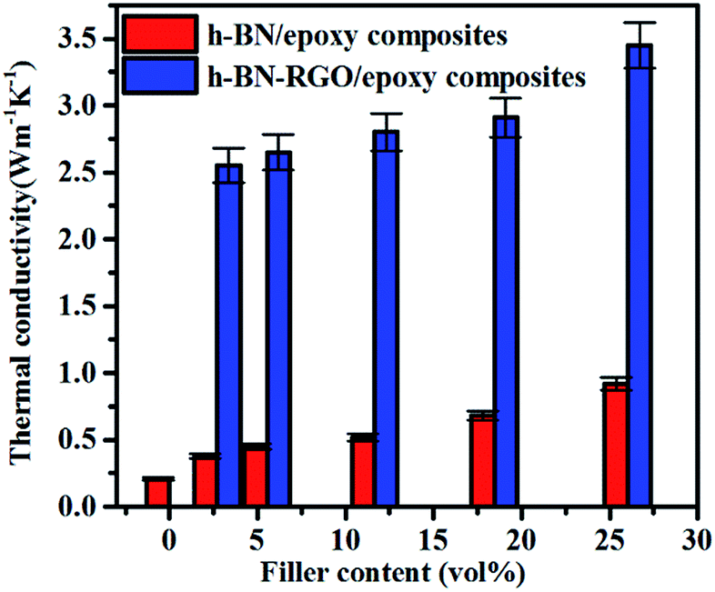
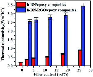
Fig. 7 shows the conductivities of the composite films prepared. The results demonstrate that the thermal conductivity increases with the fraction of the fillers consistently. Moreover, at the same filler concentration, h-BN–RGO leads to a higher thermal conductivity than pristine h-BN. As illustrated in Fig. 7, the h-BN–RGO remarkably improves the thermal conductivity, which reaches 2.80, 2.91 and 3.45 W m−1 K−1 for 11.66, 18.45 and 26.04 vol% fillers, respectively. The composite containing 26.04 vol% h-BN–RGO exhibits the highest thermal conductivity (3.45 W m−1 K−1), which is 1643% that of pure epoxy. It is also worth mentioning that the composites containing h-BN–RGO exhibit overall higher thermal conductivity than those containing h-BN fillers. This is because the agglomeration of h-BN in the epoxy matrix blocks the effective heat transport along the composites. Moreover, the agglomeration produces serious phonon scattering among the contacts with the h-BN particles, which is similar to reports in the case of carbon nanotubes.34,35 Phonons, which are defined as quantized lattice vibrations, are believed to be the dominant carriers in heat dissipating in the composite materials. Phonon scattering, which is mainly owing to the defects and interface mismatch, plays a key role in the thermal conductivity.6,36 As shown in Fig. 8, agglomeration and voids are observed, which results in increased phonon scattering, and thus showing a relatively low thermal conductivity. Table 1 summarizes previously reported thermal conductivity (K) for polymer composites with boron nitride (BN) fillers, including microBN and nanoBN (nanoparticle, nanosheets, and nanotubes). The data indicate that the h-BN–RGO hybrid exhibits an excellent ability to improve the thermal conductivity of epoxy composite.
 |
| | Fig. 7 The thermal conductivity of h-BN/epoxy and h-BN–RGO/epoxy composites with various filler content. | |
 |
| | Fig. 8 Comparison between the simulated thermal conductivity based on the EMA model and the experimental values. | |
Table 1 Comparison of thermal conductivity of our h-BN–RGO/epoxy composite with the reported polymer composites filled with different BN-based fillers
| Fillers |
Matrix |
Loading (vol.) |
K (W m−1 K−1) |
References and year |
| BN |
Epoxy |
18.5 |
1.18 |
2014 (ref. 37) |
| BNNS |
Bismaleimide |
11.7 |
1.1 |
2014 (ref. 38) |
| Aggregated BN |
Epoxy |
42.8 |
3.6 |
2014 (ref. 39) |
| BNNS |
Polystyrene |
67.6 |
1.1 |
2015 (ref. 40) |
| Oriented BNNS |
Silicone rubber |
30.8 |
5.47 |
2015 (ref. 41) |
| BN nanotube |
Epoxy |
18.5 |
2.77 |
2013 (ref. 42) |
| BNNS |
Epoxy |
18.5 |
0.62 |
2014 (ref. 43) |
| Oriented BNNS |
Natural rubber |
30.8 |
2.08 |
2015 (ref. 44) |
| Aligned BN |
Silicone rubber |
18 |
1.1 |
2014 (ref. 44) |
| h-BN–RGO |
Epoxy |
26 |
3.45 |
This work |
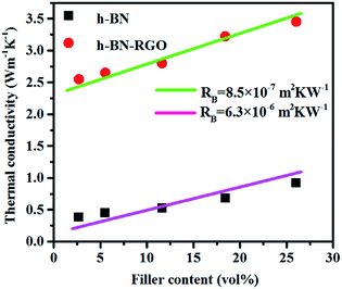
Several theoretical models have been developed to predict the thermal conductivity of polymer composites. In this work, we used the Maxwell-Garnett effective medium approximation (EMA), which works well for f < 40% (ref. 45 and 46) to analyze our experimental results. The thermal conductivity of the epoxy composites are defined as eqn (2):47
| |
 | (2) |
where
K is the thermal conductivity of composite,
KP and
Km are thermal conductivity of the filler and matrix materials,
f is the volume fraction,
H is the thickness of filler flake and
RB is the thermal boundary resistance. In this work, we assume the value of
KP are 180 W m
−1 K
−1 and 270 W m
−1 K
−1 for h-BN/epoxy composites and h-BN–RGO/epoxy composites, respectively. The value of
Km is 0.2 W m
−1 K
−1, and the value of
H is 300 nm. The value of
RB achieved from
eqn (2) for the h-BN/epoxy composite is 6.3 × 10
−6 m
2 kW
−1, which is greater than that of h-BN–RGO/epoxy composite (8.5 × 10
−7 m
2 kW
−1). The results indicate that RGO decrease the thermal contact resistance and improve the compatibility between h-BN and epoxy and the thermal conductivity of the composites significantly.
For h-BN–RGO/epoxy composites, the increase of thermal conductivity can be explained as follows. The effect of h-BN absorbing RGO promotes the dispersion of the fillers and remove agglomeration and voids, and thus reduces the number of effective phonon scattering centers, which results in the enhancement of thermal conductivity. Fig. 9 shows the fracture morphology of h-BN–RGO/epoxy composite, in which the surface is much smoother than that of h-BN/epoxy, indicating good dispersion of the fillers in epoxy matrix. It can be seen that aggregation and faults appear in h-BN/epoxy composites (marked arrows in Fig. 9(a)) which indicates a relative weak interaction between the filler and epoxy. The improvement of thermal conductivity could be attributed to the bridge effect of the RGO absorbing among the fillers, which is beneficial to the formation of thermal conductive pathways. Furthermore, the strong interactions among fillers could reduce the interface thermal resistance, leading to higher thermal conductivity.48
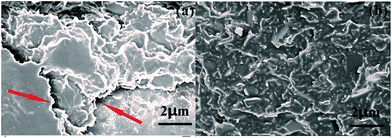 |
| | Fig. 9 SEM image of the fracture morphology of (a) h-BN/epoxy composite and (b) h-BN–RGO/epoxy composite. | |
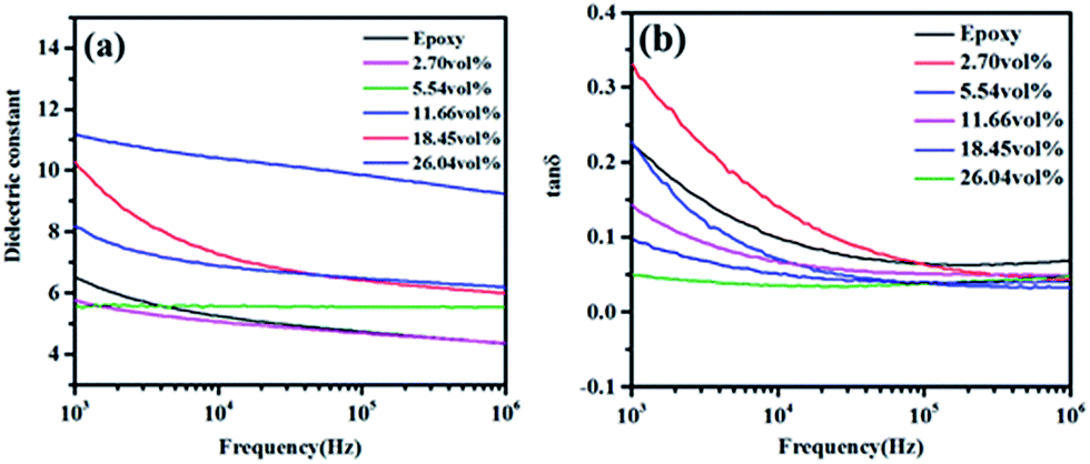
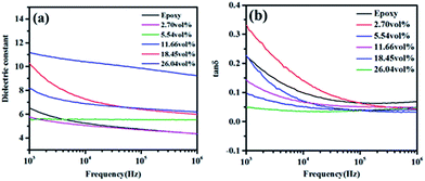
The effects of filler functionality and volume fraction on dielectric properties of h-BN–RGO/epoxy composites were examined. Fig. 10 shows the dependence of the dielectric constant and loss for the neat epoxy and h-BN–RGO composites on the frequency. As shown in Fig. 10(a), the dielectric constant of the composites decreases with the increase of the frequency. The frequency dependence of h-BN–RGO/epoxy composites is related to the interfacial polarization.49,50 Since the RGO sheets have been reduced, the electrical conductivity is higher than GO sheets. Therefore, adding the RGO sheets increases electrical currents inside the composites, which results in a charge build up at the interface when an external voltage is applied.51 However, due to the relatively high dielectric constant of h-BN and RGO, the dielectric constants of composites increased slightly. For instance, the dielectric constant increases from 5.8 for 2.70 vol% to 9.2 for 18.45 vol%. It could be obviously observed that the dielectric loss of h-BN–RGO composites with different volume fraction decreased as the frequency increased from 1 kHz to 1 MHz, as illustrated in Fig. 10(b). The result is due to the space charge polarization, which originates from the conductor–insulator interfaces. Note that adding more h-BN–RGO filler could result in an increase of the dielectric loss, and the dielectric loss of h-BN–RGO/epoxy composites keeps lower than 0.082 from 100 kHz to 1 MHz. In brief, the results indicate that the h-BN–RGO/epoxy composites have the potential in modern electronic devices requiring efficient heat transportation and an increased dielectric constant.
 |
| | Fig. 10 Dielectric properties of different volume fraction h-BN–RGO filled epoxy composites: (a) dielectric constant; (b) tan delta. | |
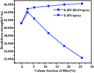
It is well known that the breakdown strength is a key factor which determines the possible maximum energy densities of the composites. Fig. 11 shows the breakdown strength of h-BN/epoxy and h-BN–RGO/epoxy composite as a function of volume fraction at room temperature. It can be seen that as the volume fraction increases, the breakdown strength values of the h-BN/epoxy composites increases slightly. Meanwhile, the h-BN–RGO/epoxy composites with 2.7 vol% rises to a maximum of 44.77 MV m−1 and then gradually decreases to a minimum of 32.31 MV m−1. For h-BN/epoxy composites, the reason of improvement is that the breakdown strength of h-BN is higher than that of epoxy.52 On the other hand, the addition of increased amount of RGO results in the decreased electric insulation property of composites by tunneling effects. In addition, the RGO sheets can reduce the agglomerations of the fillers and lead to a smaller distortions of the electrical field. It should be mentioned that the breakdown strength of composites decreases as the concentration of the filler increases (>11.66 vol%), which makes it difficult to achieve the polarization values of the composites under high electric field.
 |
| | Fig. 11 Breakdown strength of the h-BN and h-BN–RGO composites loaded with different volume fraction of fillers. | |
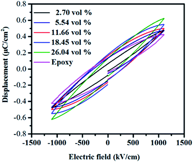
Fig. 12 presents the electric displacement–electric field (D–E) loops of the composites at a field of 1000 kV cm−1 with a frequency of 100 Hz. The maximum electric displacement of pure epoxy is 0.42 μC cm−2. With the increasing of the filler contents, the maximum electric displacement increases and obtains 0.62 μC cm−2 for the h-BN–RGO/epoxy composites with 26.04 vol%. From the figure, it can be seen that the maximum electric displacement of the composites increases as the volume fraction of fillers increases. The electric displacement is described as the following formula:
where
ε0 and
εr are permittivity of vacuum and dielectric constant of the composites, respectively. Therefore, the increased electric displacement is attributed to the increase of dielectric constant of the composites.
 |
| | Fig. 12 Electric displacement–electric field (D–E) loops of epoxy composites with different volume fraction of fillers. | |
The energy density and energy efficiency of the composites can be calculated from the electric displacement–electric field (D–E) curves using the following equations:
| |
 | (4) |
| |
 | (5) |
where
Jdischarged and
Jcharged are the discharged and charged energy densities, respectively.
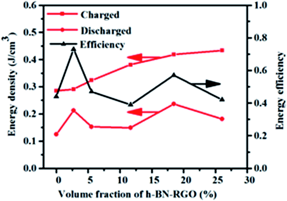
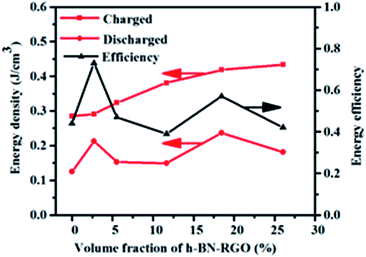
Fig. 13 exhibits the calculated energy densities and energy efficiencies. It can be seen that the charged energy densities of the composites increases with the increasing of the filler content. The maximum charged energy density reaches 0.51 J cm
−3 in the composites with 26.04 vol%, which is 79.6% higher than that of the pure epoxy. Both high energy density and high energy efficiency are required for practical applications because the energy losses usually result in heating and degenerating the performance of the composites. As illustrated in
Fig. 13, the energy efficiency reaches 77% in the composites with the 2.7 vol%, which is enhanced 175% compared to that of neat epoxy. From the experimental results, there is no direct relation between the filler concentration and the energy efficiency.
 |
| | Fig. 13 Efficiency and energy storage density of composites loaded with different volume fraction of fillers. | |
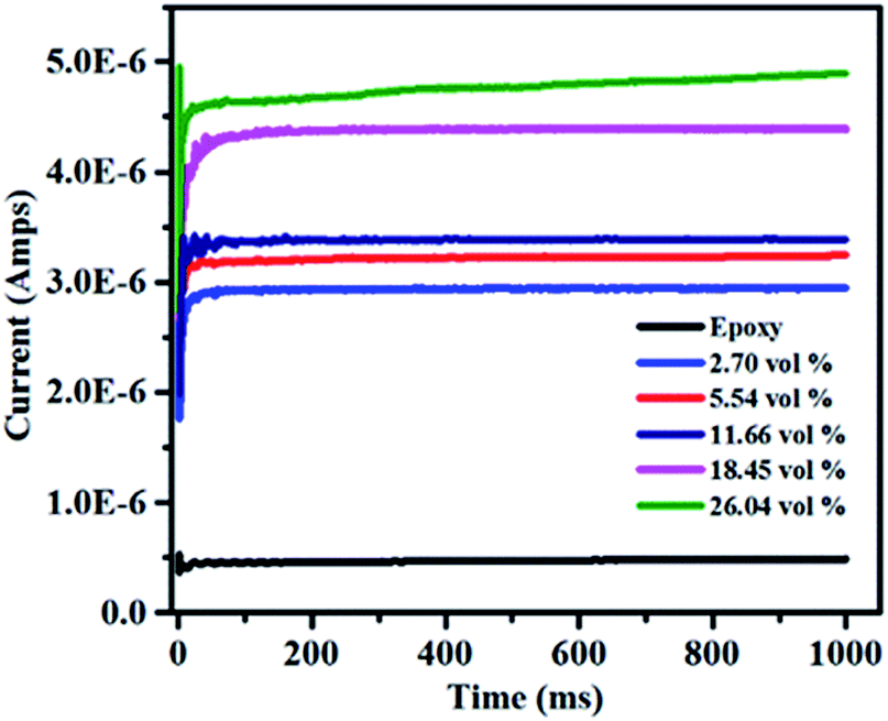
It is necessary to obtain low leakage current for the application of dielectric materials in energy density.53 The dielectric loss of dielectric materials is mostly attributed to the leakage current,54,55 especially at high electric field. The characteristic of leakage current at the applied voltage of 1000 V is shown in Fig. 14. The leakage current slightly increases from 2.9 × 10⁻⁶ to 4.9 × 10⁻⁶ amps with the volume fraction of filler increases from 2.7 vol% to 26.04 vol%. Moreover, all of the composites exhibit low leakage current at room temperature and the largest current is 4.9 × 10⁻⁶ amps. It can be explained that the electrical conductivity of the composites increases with the high RGO loading, which can make more charges to form electric current under a high applied voltage. However, the breakdown strength goes down as the filler contents increases as shown in Fig. 10. Hence, the available electric voltage to the composites in the practical application would be limited though the leakage current increases with the increase of the volume fraction of h-BN–RGO.
 |
| | Fig. 14 Leakage current of the h-BN–RGO composites loaded with different volume fraction fillers. | |
4. Conclusions
The h-BN–RGO fillers were introduced into epoxy resin to improve the thermal conductivity and energy density of the composites. Owing to the unique properties, the thermal conductivity of h-BN–RGO/epoxy exceeds to that of h-BN filler-based epoxy composites. The 26.04 vol% filled h-BN–RGO/epoxy composite exhibits the highest thermal conductivity of 3.45 W m−1 K−1, which was as high as 16 times to that of neat epoxy. In addition, the dielectric measurement implies that the h-BN–RGO/epoxy composite exhibits better dielectric properties than that of pure epoxy matrix. Compared with the epoxy, the h-BN–RGO/epoxy composites exhibit higher dielectric constant, suppressed dielectric loss, higher charged energy density and improved energy efficiency. The prepared epoxy composites exhibit both outstanding thermal conductivity and enhanced energy storage performance, which leads to good application prospects in the field of thermal management and electrical applications.
Acknowledgements
The authors acknowledge the financial support from National Natural Science Foundation of China (No. 51603226), Guangdong and Shenzhen Innovative Research Team Program (No. 2011D052 and KYPT20121228160843692), Guangdong Provincial Key Laboratory (2014B030301014), and Shenzhen Fundamental Research Program (JCYJ20150831154213681).
Notes and references
- P. Kim, L. Shi, A. Majumdar and P. L. McEuen, Phys. B, 2002, 323, 67–70 CrossRef CAS.
- T. Morishita, M. Matsushita, Y. Katagiri and K. Fukumori, J. Mater. Chem., 2011, 21, 5610 RSC.
- W.-L. Song, W. Wang, L. M. Veca, C. Y. Kong, M.-S. Cao, P. Wang, M. J. Meziani, H. Qian, G. E. LeCroy, L. Cao and Y.-P. Sun, J. Mater. Chem., 2012, 22, 17133 RSC.
- M. Bozlar, D. He, J. Bai, Y. Chalopin, N. Mingo and S. Volz, Adv. Mater., 2010, 22, 1654–1658 CrossRef CAS PubMed.
- C. Zhi, Y. Bando, T. Terao, C. Tang, H. Kuwahara and D. Golberg, Adv. Funct. Mater., 2009, 19, 1857–1862 CrossRef CAS.
- X. Huang, T. Iizuka, P. Jiang, Y. Ohki and T. Tanaka, J. Phys. Chem. C, 2012, 116, 13629–13639 CAS.
- S. Kume, I. Yamada, K. Watari, I. Harada and K. Mitsuishi, J. Am. Ceram. Soc., 2009, 92, S153–S156 CrossRef CAS.
- E.-S. Lee, S.-M. Lee, D. J. Shanefield and W. R. Cannon, J. Am. Ceram. Soc., 2008, 91, 1169–1174 CrossRef CAS.
- K. C. Yung, B. L. Zhu, T. M. Yue and C. S. Xie, J. Appl. Polym. Sci., 2010, 116, 518–527 CrossRef CAS.
- C.-M. Ye, B.-Q. Shentu and Z.-X. Weng, J. Appl. Polym. Sci., 2006, 101, 3806–3810 CrossRef CAS.
- W. Zhou, C. Wang, T. Ai, K. Wu, F. Zhao and H. Gu, Composites, Part A, 2009, 40, 830–836 CrossRef.
- J. Zeng, R. Fu, Y. Shen, H. He and X. Song, J. Appl. Polym. Sci., 2009, 113, 2117–2125 CrossRef CAS.
- A. Yu, P. Ramesh, X. Sun, E. Bekyarova, M. E. Itkis and R. C. Haddon, Adv. Mater., 2008, 20, 4740–4744 CrossRef CAS.
- Z. Han and A. Fina, Prog. Polym. Sci., 2011, 36, 914–944 CrossRef CAS.
- F. Yavari, H. R. Fard, K. Pashayi, M. A. Rafiee, A. Zamiri, Z. Yu, R. Ozisik, T. Borca-Tasciuc and N. Koratkar, J. Phys. Chem. C, 2011, 115, 8753–8758 CAS.
- B.-H. Xie, X. Huang and G.-J. Zhang, Ceram. Int., 2013, 39, 8543–8548 CrossRef CAS.
- L. Huang, P. Zhu, G. Li, F. Zhou, D. Lu, R. Sun and C. Wong, J. Mater. Sci.: Mater. Electron., 2015, 26, 3564–3572 CrossRef CAS.
- H. Shen, J. Guo, H. Wang, N. Zhao and J. Xu, ACS Appl. Mater. Interfaces, 2015, 7, 5701–5708 CAS.
- V. Tomer, G. Polizos, E. Manias and C. A. Randall, J. Appl. Phys., 2010, 108, 074116 CrossRef.
- W. Xia, Z. Xu, F. Wen and Z. Zhang, Ceram. Int., 2012, 38, 1071–1075 CrossRef CAS.
- T. Huang, X. Zeng, Y. Yao, R. Sun, F. Meng, J. Xu and C. Wong, RSC Adv., 2016, 6, 35847–35854 RSC.
- L. Huang, P. Zhu, G. Li, D. Lu, R. Sun and C. Wong, J. Mater. Chem. A, 2014, 2, 18246–18255 CAS.
- Z. Liu, L. H. Tizei, Y. Sato, Y. C. Lin, C. H. Yeh, P. W. Chiu, M. Terauchi, S. Iijima and K. Suenaga, Small, 2016, 12, 252–259 CrossRef CAS PubMed.
- A. C. Ferrari, Solid State Commun., 2007, 143, 47–57 CrossRef CAS.
- S. Bernard, F. Chassagneux, M. P. Berthet, H. Vincent and J. Bouix, J. Eur. Ceram. Soc., 2002, 22, 2047–2059 CrossRef CAS.
- S. Saha, D. V. S. Muthu, D. Golberg, C. Tang, C. Zhi, Y. Bando and A. K. Sood, Chem. Phys. Lett., 2006, 421, 86–90 CrossRef CAS.
- Y. Y. Wang, Z. H. Ni, T. Yu, Z. X. Shen, H. M. Wang, Y. H. Wu, W. Chen and A. T. S. Wee, J. Phys. Chem. C, 2008, 112, 10637–10640 CAS.
- O.-K. Park, S. Lee, H.-I. Joh, J. K. Kim, P.-H. Kang, J. H. Lee and B.-C. Ku, Polymer, 2012, 53, 2168–2174 CrossRef CAS.
- N. Liu, F. Luo, H. Wu, Y. Liu, C. Zhang and J. Chen, Adv. Funct. Mater., 2008, 18, 1518–1525 CrossRef CAS.
- T.-L. Li and S. L.-C. Hsu, J. Phys. Chem. B, 2010, 114, 6825–6829 CrossRef CAS PubMed.
- I. Kaminska, M. R. Das, Y. Coffinier, J. Niedziolka-Jonsson, J. Sobczak, P. Woisel, J. Lyskawa, M. Opallo, R. Boukherroub and S. Szunerits, ACS Appl. Mater. Interfaces, 2012, 4, 1016–1020 CAS.
- H. Cao, X. Wu, G. Yin and J. H. Warner, Inorg. Chem., 2012, 51, 2954–2960 CrossRef CAS PubMed.
- R. Kamatchi, S. Venkatachalapathy and B. Abhinaya Srinivas, Int. J. Therm. Sci., 2015, 97, 17–25 CrossRef CAS.
- S. T. Huxtable, D. G. Cahill, S. Shenogin, L. P. Xue, R. Ozisik, P. Barone, M. Usrey, M. S. Strano, G. Siddons, M. Shim and P. Keblinski, Nat. Mater., 2003, 2, 731–734 CrossRef CAS PubMed.
- P. Kim, L. Shi, A. Majumdar and P. L. McEuen, Phys. B, 2002, 323, 67–70 CrossRef CAS.
- A. L. Moore and L. Shi, Mater. Today, 2014, 17, 163–174 CrossRef CAS.
- F. Bouville, E. Maire and S. Deville, Langmuir, 2014, 30, 8656–8663 CrossRef CAS PubMed.
- J. Hou, G. Li, N. Yang, L. Qin, M. E. Grami, Q. Zhang, N. Wang and X. Qu, RSC Adv., 2014, 4, 44282–44290 RSC.
- Z. Lin, A. McNamara, Y. Liu, K.-s. Moon and C.-P. Wong, Compos. Sci. Technol., 2014, 90, 123–128 CrossRef CAS.
- H. Wu and M. R. Kessler, ACS Appl. Mater.
Interfaces, 2015, 7, 5915–5926 CAS.
- Z. Kuang, Y. Chen, Y. Lu, L. Liu, S. Hu, S. Wen, Y. Mao and L. Zhang, Small, 2015, 11, 1655–1659 CrossRef CAS PubMed.
- X. Huang, C. Zhi, P. Jiang, D. Golberg, Y. Bando and T. Tanaka, Adv. Funct. Mater., 2013, 23, 1824–1831 CrossRef CAS.
- Q. Li, G. Zhang, F. Liu, K. Han, M. R. Gadinski, C. Xiong and Q. Wang, Energy Environ. Sci., 2015, 8, 922–931 CAS.
- T. Fujihara, H.-B. Cho, T. Nakayama, T. Suzuki, W. Jiang, H. Suematsu, H. D. Kim, K. Niihara and J. Blendell, J. Am. Ceram. Soc., 2012, 95, 369–373 CrossRef CAS.
- C.-W. Nan, R. Birringer, D. R. Clarke and H. Gleiter, J. Appl. Phys., 1997, 81, 6692 CrossRef CAS.
- S. H. Xie, Y. Y. Liu and J. Y. Li, Appl. Phys. Lett., 2008, 92, 243121 CrossRef.
- H. Chen, V. V. Ginzburg, J. Yang, Y. Yang, W. Liu, Y. Huang, L. Du and B. Chen, Prog. Polym. Sci., 2016, 59, 41–85 CrossRef CAS.
- X. Wu, H. Liu, Z. Tang and B. Guo, Compos. Sci. Technol., 2016, 123, 179–186 CrossRef CAS.
- N. Fuse, H. Sato, Y. Ohki and T. Tanaka, IEEE Trans. Dielectr. Electr. Insul., 2009, 16, 524–530 CrossRef CAS.
- N. Tagami, M. Hyuga, Y. Ohki, T. Tanaka, T. Imai, M. Harada and M. Ochi, IEEE Trans. Dielectr. Electr. Insul., 2010, 17, 214–220 CrossRef CAS.
- Y. Yao, X. Zeng, K. Guo, R. Sun and J.-b. Xu, Composites, Part A, 2015, 69, 49–55 CrossRef CAS.
- Prateek, V. K. Thakur and R. K. Gupta, Chem. Rev., 2016, 116, 4260–4317 CrossRef CAS PubMed.
- Z. Xie, B. Peng, S. Meng, Y. Zhou, Z. Yue and S. E. Trolier-McKinstry, J. Am. Ceram. Soc., 2013, 96, 2061–2064 CrossRef CAS.
- J. Li, S. I. Seok, B. Chu, F. Dogan, Q. Zhang and Q. Wang, Adv. Mater., 2009, 21, 217–221 CrossRef CAS.
- T. Tanaka, IEEE Trans. Dielectr. Electr. Insul., 2005, 12, 914–928 CrossRef CAS.
|
| This journal is © The Royal Society of Chemistry 2017 |
Click here to see how this site uses Cookies. View our privacy policy here. 
 Open Access Article
 This Open Access Article is licensed under a
  abc,
Xiaoliang Zengbd,
Yimin Yaobd,
Rong Sun*b,
Fanling Meng*a,
Jianbin Xue and
Chingping Wongf
abc,
Xiaoliang Zengbd,
Yimin Yaobd,
Rong Sun*b,
Fanling Meng*a,
Jianbin Xue and
Chingping Wongf