
 Open Access Article
 This Open Access Article is licensed under a Creative Commons Attribution-Non Commercial 3.0 Unported Licence
Polypropylene/poly(methyl methacrylate)/graphene composites with high electrical resistivity anisotropy via sequential biaxial stretching
Feng Youab,
Xinye Lib,
Liang Zhanga,
Dongrui Wang *a,
Chang-Yong Shic and
Zhi-Min Dang†
*a
*a,
Chang-Yong Shic and
Zhi-Min Dang†
*a
aDepartment of Polymer Science and Engineering, School of Chemistry and Biological Engineering, University of Science and Technology Beijing, Beijing 100083, China. E-mail: wangdr@ustb.edu.cn; dangzm@ustb.edu.cn
bDepartment of Polymer Science and Engineering, School of Material Science and Engineering, Wuhan Institute of Technology, Wuhan 430073, China
cElements Department, Beijing Institute of Fashion Technology, Beijing 100029, China
First published on 24th January 2017
Abstract
An efficient strategy is developed for the fabrication of graphene-filled polypropylene (PP) nanocomposites with graphene nanosheets orderly oriented in the in-plane direction. The nanocomposites with an anisotropic coefficient as high as 35![[thin space (1/6-em)]](https://www.rsc.org/images/entities/char_2009.gif) 000 in electrical resistivity were fabricated by a sequential biaxial stretching process. Polymethylmethacrylate (PMMA) was employed to bridge graphene to the non-polar PP matrix, which facilitates the homogeneous dispersion and the orientation of the chemically converted graphene nanosheets. A PMMA/graphene masterbatch was firstly prepared and blended into the PP matrix. During the biaxial stretching, the PMMA/graphene phase was transformed from beads to sheets, which induced the in-plane orientation of the graphene nanosheets. As a consequence, the storage modulus and the conductivity of the nanocomposites were improved in the in-plane direction. The effects of graphene content and draw ratio on the anisotropy of the PP/PMMA/graphene nanocomposites were discussed in detail. This strategy of orientation-effectiveness and cost-effectiveness can be potentially integrated with commercialized biaxial stretching processes to produce high-quality anisotropic polyolefin/graphene composite films.
000 in electrical resistivity were fabricated by a sequential biaxial stretching process. Polymethylmethacrylate (PMMA) was employed to bridge graphene to the non-polar PP matrix, which facilitates the homogeneous dispersion and the orientation of the chemically converted graphene nanosheets. A PMMA/graphene masterbatch was firstly prepared and blended into the PP matrix. During the biaxial stretching, the PMMA/graphene phase was transformed from beads to sheets, which induced the in-plane orientation of the graphene nanosheets. As a consequence, the storage modulus and the conductivity of the nanocomposites were improved in the in-plane direction. The effects of graphene content and draw ratio on the anisotropy of the PP/PMMA/graphene nanocomposites were discussed in detail. This strategy of orientation-effectiveness and cost-effectiveness can be potentially integrated with commercialized biaxial stretching processes to produce high-quality anisotropic polyolefin/graphene composite films.
Introduction
Graphene, a well-known two-dimensional nanomaterial, has attracted tremendous attention since its first successful preparation in 2004.1 It has been regarded as the most promising material for many advanced applications due to its extraordinary mechanical, thermal, and electrical properties.2 In the field of polymer composites, graphene has been intensively investigated as a promising filler to enhance the physical properties of polymers such as mechanical strength, electrical conductivity, gas barrier, etc.3,4 It is well-known that nano-fillers with high aspect ratios (AR) will be more efficient in improving the mechanical strength and other physical properties of the polymer matrix.5 The theoretical specific surface area of graphene is as high as 2630 g m−2, which suggests a huge AR because of its ultralow thickness of only one atom.2 Consequently, a significant difference in physical properties between the in-plane direction and out-plane direction of graphene can be expected.The electrical conductivity and mechanical strength of graphene in the in-plane direction are much higher than those in the out-plane direction. Thus, the anisotropy in physical properties can be obtained by the orientation of graphene. For example, Liang et al. have observed a remarkable anisotropy of functionalized multilayer graphene sheets (fMGs).6 High electrical conductivity (∼386 S cm−1), high thermal conductivity (∼112 W m−1 K−1 at 25 °C), and ultralow coefficient of thermal expansion (∼−0.71 ppm K−1) were obtained in the in-plane direction of fMGs. Therefore, polymer nanocomposites with anisotropic properties can be expected by incorporating well-aligned graphene nanosheets. However, conventional blending techniques often lead to a random distribution of graphene. Notably, two methods can realize the orientation of graphene in the polymer matrix. One is the self-assembly technology7,8 which can only be available in solution surroundings. For instance, Kulkarni et al. have prepared laminated polyelectrolyte/graphene oxide nanocomposites by incorporating negative charged functionalized graphene oxide (GO) layers into polyelectrolyte via Langmuir–Blodgett (LB) deposition.9 The in-plane elastic modulus of the nanocomposites was significantly enhanced from 1.5 GPa for simple layer-by-layer (LbL) membranes to about 20 GPa for the membranes encapsulated with only 8.0 vol% of GO. Yousefi et al. have prepared polyurethane (PU)-based composite films containing highly aligned graphene sheets through an environmentally benign process and the resultant composites exhibited a very low electrical conductivity percolation threshold of 0.078 vol%.10 Well-aligned graphene nanosheets in the polymer matrix can also be obtained by wet spinning or casting.11 Shin has successfully realized a synergistic toughening of composite fibers by self-alignment of reduced graphene oxide and carbon nanotubes in solution-spun poly(vinyl alcohol) fibers. The gravimetric toughness approached 1000 J g−1, which had far exceeded that of Kevlar (78 J g−1).12 The other method to realize the oriented distribution of graphene in the polymer matrix is using uniaxial stretching or biaxial stretching. Though the orientation degree of fillers in the polymer matrix through self-assembly is higher than that of using stretching, the stretching technique is more convenient for industrial practice because it does not need solvent which is inevitable in self-assembly techniques. The latter approach is often used to realize the orientation of polymeric or inorganic fillers in polymer manufacturing.
Hot stretching is an efficient and facile method to transform morphologies or improve the ultimate properties in the stretching direction of resultant polymer nanocomposites.13 For instance, the biaxially oriented polypropylene (BOPP) films by using hot stretching have become commercial products for several years, which have played a great role in packaging industries. Smook et al. have investigated the effect of draw ratio on the morphologies and structures of ultra-high molecular weight polyethylene (UHMWPE) in hot-drawing by differential scanning calorimetry.14 A shish-kebab morphology was found to transform into a smooth fibrillar structure for UHMWPE in the drawing process and the melting point of UHMWPE increased with draw ratios. Tang et al. have used uniaxial stretching to align lead zirconate titanate (PZT) nanowires in a thermal plastic matrix.15 A maximum energy density in the in-plane direction is as high as 1.28 J cm−3 for nanocomposites with a volume fraction of 40% PZT nanowires. Shen et al. have comprehensively investigated the development of electronic conducting networks of carbon nanotubes (CNT) in PP matrix during the simultaneous biaxial stretching process. They found the resistivity of the stretched films with 2.2 vol% of CNT was dramatically decreased by seven orders of magnitude.16,17 Very recently, Leung et al. have prepared ultra-drawn nanocomposites with aligned liquid crystal polymer fibrils and graphene nanoplatelets. They found these nanocomposites possessed much higher thermal conductivity than that of the neat polymer.18 One particular hot stretching can be realized through the so-called forced assembly process by using multilayer coextrusion equipment.19 For instance, the orientation of graphene in poly(methyl methacrylate)/polystyrene (PMMA/PS) and PMMA/PMMA multilayer films has been achieved by Li, et al. using a forced assembly.20 A significant reinforcement of 118% in the multilayer films with graphene well-oriented was achieved, which is much higher than the counterparts with graphene randomly dispersed.
It should be noted that most of the graphene/polymer nanocomposites with graphene nanosheets well-aligned employ polar polymer matrix owing to a relatively strong interaction between the graphene and the polymer chains.21–23 In contrast, the orientation of graphene nanosheets in polyolefin matrix is challenging, though these polyolefin nanocomposites are highly desired in many industry fields including electronics, packaging, smart textiles, etc. The challenge should be mainly caused by the weak interfacial interaction between graphene and polyolefin chains.24 Therefore, in this work we develop a facile strategy to realize the orientation of graphene nanosheets in PP matrix through biaxial hot stretching, in which PMMA is employed to bridge the graphene and PP and to enhance their interfacial interactions. PP/graphene nanocomposites with an anisotropic coefficient as high as 35000 in electrical resistivity can be obtained by carefully controlling the amount of graphene and the draw ratio of stretching. The effects of graphene loading and draw ratio on the thermal behaviors, dynamic mechanical properties, and anisotropic electrical resistivity of the resultant PP/PMMA/graphene nanocomposites are discussed in detail.
Experimental
Materials
PP (T30S, MFI = 3.0 g/10 min) was obtained from Maoming Petroleum Chemical, China. PMMA (CM205, MFI = 12.5 g/10 min) was purchased from Taiwan Qimei Company. Polypropylene-graft-maleic anhydride (MAPP) with the maleic anhydride grafting ratio of 1.5 wt% was prepared in laboratory. Graphite powder (Sinopharm Chemical Reagent Co. Ltd.) with a size of 300–400 mesh was sieved out before use. All other reagents and solvents were analytical grade products and used without further purification.Preparation of PMMA/graphene masterbatch
The graphite oxide was firstly prepared from natural graphite powders following the modified Hummers method.25 The dry graphite oxide powder (1.5 g) was dispersed in water (1.2 L) to form a uniform graphene oxide (GO) suspension through exfoliation under ultrasonication. PMMA pellets (3.0 g) was dissolved in 300 mL of N,N-dimethylformamide (DMF) and the resultant PMMA solution was slowly poured into the GO suspension under mechanical stirring. A stable suspension of GO in which the PMMA wrapped GO nanosheets was obtained. Then the PMMA/GO suspension was reduced by hydrazine hydrate (3 mL) at 90 °C for 8 h. The obtained PMMA/graphene suspension was filtered over a polytetrafluoroethylene (PTFE) membrane with a pore size of 2.0 μm and washed with excessive ethanol. Finally, the PMMA/graphene powder (3.9 g) was obtained after drying at 60 °C under vacuum for 48 h. The reduction yield from GO to graphene is estimated to be 0.6 by weighing the mass difference of GO and resultant graphene in control experiments without the appearance of PMMA. Therefore, the graphene loading in PMMA/graphene masterbatch is 13 vol%.Fabrication of PP/PMMA/graphene nanocomposites
Certain amounts of PP, PMMA, and the PMMA/graphene masterbatch were melt blended through a Haake miniLab micro compounder (Thermo Fisher Scientific, USA) at 180 °C with a screw speed of 80 rpm for 8 min. 3 vol% of MAPP was also incorporated in the blending process to improve the compatibility between PP and PMMA. PP/PMMA/graphene nanocomposites with three different graphene loadings (0.5, 1.5, and 2.5 vol%) were fabricated, in which the total volume ratio of PP/MAPP to PMMA is controlled to be 7:3. Table 1 lists the composition of various PP/PMMA/graphene nanocomposites. The resultant nanocomposites were then compression molded to square plates with the dimension of 60 × 60 × 1 mm3 at 180 °C for 15 min.
| Sample entry | PP, vol% | MAPP, vol% | PMMA, vol% | Graphene, vol% |
|---|---|---|---|---|
| 1 | 67.0 | 3.0 | 30.0 | 0 |
| 2 | 66.6 | 3.0 | 29.9 | 0.5 |
| 3 | 66.0 | 3.0 | 29.5 | 1.5 |
| 4 | 65.2 | 3.0 | 29.3 | 2.5 |
The sequential biaxial stretching of PP/PMMA/graphene nanocomposites, as schematically showed in Fig. 1, was carried out by using a laboratory-made equipment. The stretching was performed at 150 °C under a constant speed of 10 mm min−1. Before each step of stretching, the composite films were rested for 5 min. Two draw ratios (l/l0), 1.5 and 2.4, were conducted in this work. For the unstretched benchmarks, the draw ratio was denoted as 1.0.
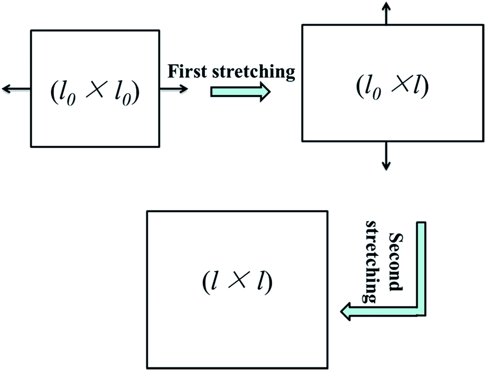 | ||
| Fig. 1 Schematic description of the sequential biaxial stretching process. | ||
Characterization
X-ray photoelectron spectroscopy (XPS) was recorded on a Kratos AXIS ULTRADLD system (Japan), using monochromatic Al Kα radiation as the source. The XPS spectra were fitted by using an XPS PEAK software to determine the changes in the atomic ratios of carbon to oxygen. X-ray diffraction (XRD) patterns of samples were collected by using a D/MAX 2500 system (Rigaku, Japan) with a Cu Kα radiation source (40 kV, 150 mA). Thermal gravimetric analysis (TGA) was analyzed by a HCT-3 system (Beijing Henven Scientific, China) with a heating rate of 10 °C min−1 under nitrogen atmosphere. The graphene sample from PMMA/graphene masterbatch for XPS, XRD and TGA measurements was obtained by removing PMMA with excess DMF solvent. The fracture surfaces of samples were sputter-coated with gold and observed by using an S4700 field emission scanning electron microscope (SEM, HITACHI, Japan) under an accelerating voltage of 20 kV. The samples were etched by DMF for 8 h to remove the dispersed PMMA phase before observation. Thermal properties of PP/PMMA blends and PP/PMMA/graphene nanocomposites were performed by using a differential scanning calorimetry (DSC-60, SHIMADZU, Japan). The samples were heated from 30 °C to 200 °C with a heating rate of 10 °C min−1 under nitrogen atmosphere. The dynamic mechanical (DMA) properties of samples with dimensions of 25 × 4 × 1 mm3 were conducted on a DMA-Q800 (TA instruments, USA) machine. A tensile mode with a frequency of 1 Hz and a heating rate of 3 °C min−1 from 20 °C to 165 °C was adopted. The electrical resistivity of square plates was tested by using a digital-mode resistivity determiner (6517B, Keithley, USA). The high limit of electrical resistance measurement can reach 1016 Ω.Results and discussion
Chemical structure of graphene
The XPS profiles of GO and graphene are presented in Fig. 2a and b. The C1s spectra of them were compared by deconvoluting each curve into four peaks, which correspond to C![[double bond, length as m-dash]](https://www.rsc.org/images/entities/char_e001.gif) C (sp2 carbon, ∼284.8 eV), C–O (hydroxyl and epoxy, ∼286.7 eV), CO (carbonyl, ∼288.3 eV) and O–CO (carboxyl, ∼290.3 eV), respectively.26,27 The C–O and CO groups are clearly observed in the XPS spectrum of GO. After reduced by hydrazine hydrate, the intensity of the oxygen functional groups dramatically decreased in the spectrum of graphene sample (as shown in Fig. 2b), indicating the successful reduction of GO. The XRD patterns and TGA curves of GO and graphene are given in Fig. 2c and d. The interlayer distance of GO is about 0.99 nm (2θ = 8.9°), this is a typical monolayer distance for GO nanosheets. In comparison, graphene shows a broad peak at 2θ = 24.8° and the corresponding interlayer distance is 0.34 nm, suggesting the formation of the graphite-like structure due to the aggregation of graphene nanosheets. The mass loss of graphene in TGA curves (Fig. 2d) is much lower than that of GO, giving another evidence for the removal of oxygen-containing groups of GO during reduction.
C (sp2 carbon, ∼284.8 eV), C–O (hydroxyl and epoxy, ∼286.7 eV), CO (carbonyl, ∼288.3 eV) and O–CO (carboxyl, ∼290.3 eV), respectively.26,27 The C–O and CO groups are clearly observed in the XPS spectrum of GO. After reduced by hydrazine hydrate, the intensity of the oxygen functional groups dramatically decreased in the spectrum of graphene sample (as shown in Fig. 2b), indicating the successful reduction of GO. The XRD patterns and TGA curves of GO and graphene are given in Fig. 2c and d. The interlayer distance of GO is about 0.99 nm (2θ = 8.9°), this is a typical monolayer distance for GO nanosheets. In comparison, graphene shows a broad peak at 2θ = 24.8° and the corresponding interlayer distance is 0.34 nm, suggesting the formation of the graphite-like structure due to the aggregation of graphene nanosheets. The mass loss of graphene in TGA curves (Fig. 2d) is much lower than that of GO, giving another evidence for the removal of oxygen-containing groups of GO during reduction.
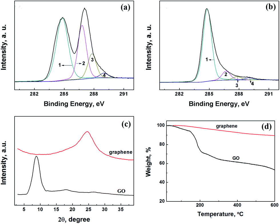 | ||
| Fig. 2 Chemical structure characterization of GO and graphene. (a) and (b) are X-ray photoelectron spectroscopy of GO and graphene, respectively. Peaks 1, 2, 3, and 4 correspond to CC (sp2 carbon, ∼284.8 eV), C–O (hydroxyl and epoxy, ∼286.7 eV), CO (carbonyl, ∼288.3 eV) and O–CO (carboxyl, ∼290.3 eV). (c) and (d) are X-ray diffraction patterns and TGA curves of GO and graphene. | ||
Effect of temperature on the deformation capability of PP and PMMA in PP/PMMA/graphene nanocomposites
It is known that the dispersion of graphene in PP matrix is rather poor because of the hydrophobic nature and low polarity of polyolefin.24 To deal with this trouble, the PMMA/graphene masterbatch was first fabricated to realize a selective localization of graphene in PMMA phase, which will be demonstrated in the following section. The orientation of graphene in PP matrix can be induced during the morphological transformation of PMMA phase from beads to sheets. In other words, graphene will be aligned in PMMA sheet during the phase transformation of PMMA. To achieve this goal, the deformation capability of PMMA must be higher than that of PP during the stretching process. Otherwise the morphological transformation of PMMA would not occur.Dynamic mechanical analysis was conducted to investigate the effect of temperature on the deformation capability of PMMA and PP. Fig. 3 gives the comparison of storage modulus of PP, PMMA and the PMMA/graphene masterbatch under different temperature. It is clear that PMMA and PMMA/graphene exhibited higher storage modulus than that of PP in the low-temperature region. The modulus of PMMA/graphene with the filler loading of only 2.5 vol% is even higher than PMMA by 24% at 30 °C due to the reinforcing effect of graphene. Fortunately, the modulus curves of PMMA and PMMA/graphene undergo a sharp decrease when the temperature approached 90 °C. As a consequence, both of PMMA and PMMA/graphene exhibit storage modulus lower than PP when the temperature exceeded 110 °C. This should be attributed to the phase transition of PMMA from glassy state to rubbery state. Subsequently, the chain segment motion of PMMA is motivated, and the deformation will become easier during the process of stretching. At the same temperature, the crystalline blocks of PP are remained, which is essential to keep the storage modulus of PP at a relatively high level. The storage modulus ratios versus temperature of PMMA and PMMA/graphene to PP (E′PMMA/E′PP and E′masterbatch/E′PP) are given in Fig. 3b. The results suggested that the lowest temperature to render the deformation of PMMA phase in PP is ca. 110 °C, under which the storage modulus ratio equals to 1. Further increasing the temperature is welcome to the deformation of PMMA dispersed phase and the stretching of PP matrix. While the operation temperature for stretching was preset as 150 °C by taking the melting point (Tm) of PP (∼160 °C) into account.
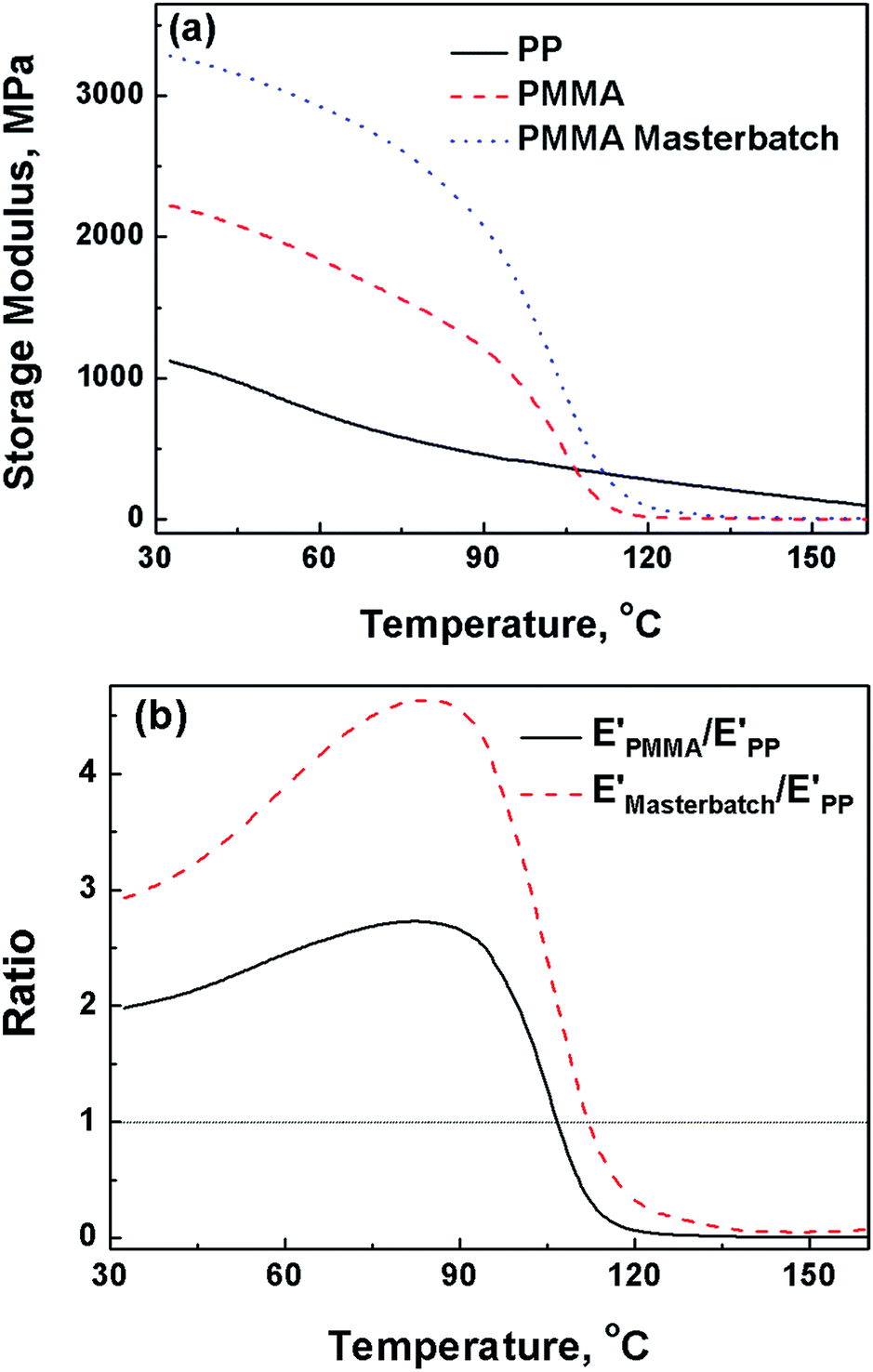 | ||
| Fig. 3 Storage modulus of PP, PMMA, and PMMA/graphene masterbatch with the graphene loading of 13 vol% as a function of temperature: (a) the storage modulus; (b) the storage modulus ratio of PMMA and PMMA masterbatch to PP. | ||
Morphological transformation of PP/PMMA/graphene nanocomposites
The morphologies of fracture surfaces of PP/PMMA/graphene nanocomposites at different draw ratios are displayed in Fig. 4. The SEM images were observed from the in-plane direction for each sample. PMMA spherical dispersed phase with an average diameter of 10 μm can be discovered in the unstretched PP/PMMA/graphene nanocomposites, and the spheres transformed into sheet-like shape when the draw ratio approached 1.5. Large voids, corresponding to the etched PMMA phase, can be found on the fracture surfaces of PP/PMMA/graphene nanocomposites when the draw ratio further increased to 2.4, revealing the PMMA has been well oriented in PP matrix after biaxial stretching process. It should also be mentioned that some graphene nanosheets can still be observed on the fractured surfaces even after the selective etching of PMMA by using DMF (as shown in Fig. 4c). It was expected that most of the graphene nanosheets are localized in PMMA phase owing to the pre-dispersion of graphene in PMMA and the strong interactions between them. Nonetheless, the appearance of graphene gives intuitive evidence that their orientation in PP matrix will enhanced with the draw ratios. Therefore, the SEM images can clearly demonstrate that graphene nanosheets are randomly dispersed throughout the unstretched PP/PMMA/graphene samples, while they tend to align in the in-plane direction as the draw ratio increases. | ||
| Fig. 4 SEM graphs of fracture surfaces of PP/PMMA blend and PP/PMMA/graphene nanocomposite. The PMMA phase was etched by immersing samples in N,N-dimethylformamide for 8 h before observation. (a1), (a2) and (a3) represent the biaxially stretched PP/PMMA blend under the draw ratio of 1.0, 1.5, and 2.4; (b1), (b2) and (b3) represent the biaxially stretched PP/PMMA/graphene filled with 2.5 vol% of graphene under the draw ratio of 1.0, 1.5, and 2.4; (c1), (c2) and (c3) are the magnification of (b1), (b2) and (b3), respectively. The red circles and arrows show the residual crumped graphene nanosheets and their orientation direction, respectively. | ||
Thermal behavior of PP/PMMA/graphene nanocomposites
The thermal behavior of PP/PMMA/graphene nanocomposites before stretching was tested by using DSC and DMA. Typical results are summarized in Fig. 5 and 6. Little change was found in the Tm of PP for PP/PMMA/graphene nanocomposites with different graphene loadings. However, the glass transition temperature (Tg, the peak of tanδ of storage modulus) of PMMA, as shown in Fig. 6, increased from 110.0 °C to 116.2 °C when the graphene loading increased from 0 to 2.5 vol%. These observations suggest that graphene is selectively dispersed in PMMA phase rather than PP matrix due to the relatively strong interactions between graphene and PMMA macromolecular chain segment. Consequently, the Tg of PMMA rather than the Tm of PP is increased.
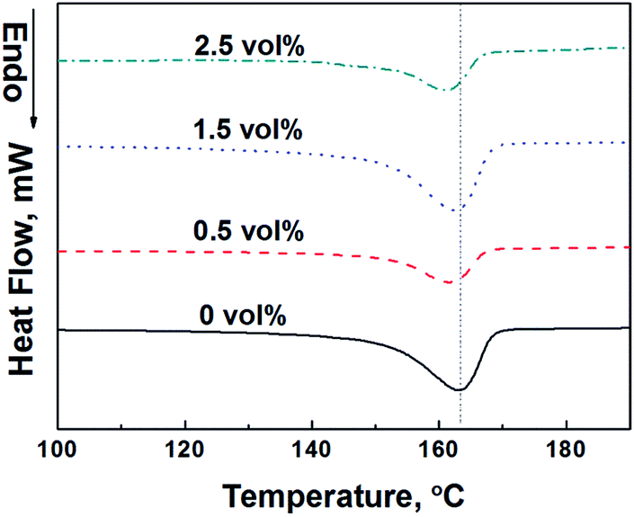 | ||
| Fig. 5 DSC curves of PP/PMMA/graphene nanocomposites with various graphene loadings. | ||
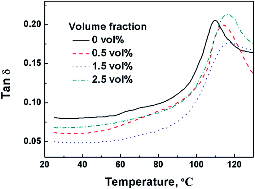 | ||
| Fig. 6 tanδ curves versus temperature of PP/PMMA/graphene nanocomposites with various graphene loadings. | ||
The effect of draw ratio on the thermal behavior of PP/PMMA/graphene nanocomposites with different graphene loadings is depicted in Fig. 7 and 8. This time, both the Tm of PP and the Tg of PMMA increase with draw ratios. Before stretching, the Tm of PP in PP/PMMA blends is around 163.0 °C, an apparent increase of Tm (6.7 °C) is detected as the draw ratio approaches to 1.5. An obvious shoulder melting peak at the low-temperature side is also observed for PP/PMMA blends when the draw ratio further increases to 2.4. Similar results are also observed in PP/PMMA blends containing 0.5 vol% and 2.5 vol% of graphene. The high Tm represents the highly chain-extended and the highly oriented crystalline blocks formed during hot drawing, while the low Tm may be due to the melting of strained non-crystalline region and some partially oriented lamella.28 The thermal transition temperatures under different draw ratios are listed in Table 2. The Tm of PP in PP/PMMA blends did not increase with the graphene loadings at the same draw ratio. Therefore, graphene has little effect on the Tm of PP in PP/PMMA/graphene nanocomposites, which is consistent with the DSC results in Fig. 5. On the other hand, the melting endotherm ratio of high Tm to low Tm of PP decreased when the graphene loading increased from 0 to 2.5 vol%, this may be caused by the hindrance of oriented PMMA/graphene phase to the crystallization of PP. However, the Tg of PMMA in PP/PMMA blends increased from 110.0 °C to 114.1 °C as the draw ratio was raised to 2.4. It was further improved to 121.5 °C for PP/PMMA/graphene nanocomposites with 2.5 vol% of graphene. Both the PMMA chains and chain segments can be induced to orientate by hot stretching, leading to higher restriction on the mobility. In addition, the Tg of PP/PMMA/graphene nanocomposites is also increased with graphene loading.
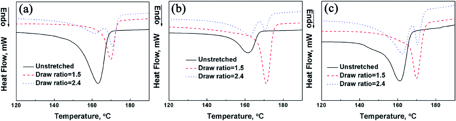 | ||
| Fig. 7 DSC curves of PP/PMMA blends and PP/PMMA/graphene nanocomposites with various draw ratios: (a) is PP/PMMA blends; (b) and (c) are the PP/PMMA/graphene nanocomposites with 0.5 vol% and 2.5 vol% of graphene loadings, respectively. | ||
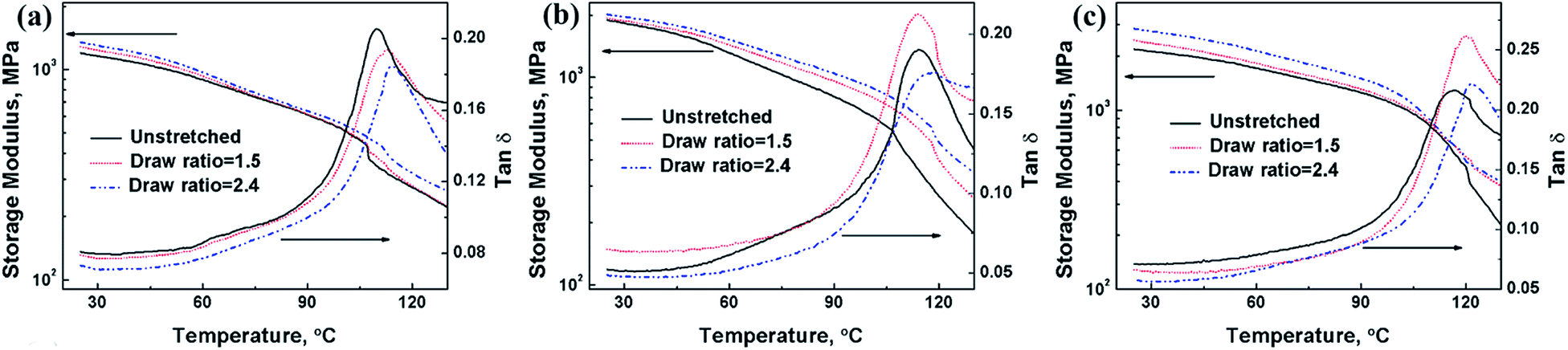 | ||
| Fig. 8 The storage modulus and tanδ curves versus temperature for PP/PMMA blends and PP/PMMA/graphene nanocomposites under various draw ratios: (a) is PP/PMMA blends; (b) and (c) are the PP/PMMA/graphene nanocomposites with 0.5 vol% and 2.5 vol% of graphene loadings, respectively. | ||
| Volume fraction of graphene, vol% | Unstretched | Draw ratio = 1.5 | Draw ratio = 2.4 | |||
|---|---|---|---|---|---|---|
| Tg, °C | Tm, °C | Tg, °C | Tm, °C | Tg, °C | Tm, °C | |
| 0 | 110.0 | 163.0 | 112.9 | 169.7 | 114.1 | 170.8 |
| 0.5 | 114.1 | 162.0 | 114.3 | 171.1 | 118.2 | 170.5 |
| 2.5 | 116.2 | 161.1 | 119.9 | 169.9 | 121.5 | 170.3 |
The orientation of PMMA/graphene in the nanocomposites will lead to the enhancement of the modulus in the in-plane direction of biaxial stretching. The effects of graphene loadings and draws ratios on the in-plane storage modulus of PP/PMMA/graphene nanocomposites are shown in Fig. 8. Large increase in the storage modulus of PP/PMMA was achieved by incorporating graphene. A 57.5% and an 82.6% of increment in the storage modulus at 25 °C were obtained for the PP/PMMA/graphene nanocomposites with 0.5 vol% and 2.5 vol% of graphene, respectively. The storage modulus PP/PMMA/graphene nanocomposites is also increased with draw ratios, while most of the tanδ values of PP/PMMA/graphene nanocomposites decreased with draw ratios, indicating the local motions of chain segments of PMMA were suppressed due to orientation.
The electrical resistivity of PP/PMMA/graphene nanocomposites
Fig. 9 shows the effect of draw ratios on the electrical resistivity of PP/PMMA/graphene nanocomposites. The electrical resistivity of the nanocomposites in the in-plane direction (ρ∥) and the thickness direction (ρ⊥) were measured and compared. For the unstretched PP/PMMA blends, the electrical resistivity (ρ0) is as high as 6.3 × 10¹⁶ Ω cm, and the stretching affects little on the resistivity. After incorporation of only 0.5 vol% of graphene, the ρ0 of PP/PMMA decreases to 4.5 × 10¹⁴ Ω cm. During the biaxial stretching process, the ρ∥ and ρ⊥ of PP/PMMA/graphene nanocomposites changed in different manners. As shown in Fig. 9b and c, the ρ∥ is greatly reduced as draw ratio goes up while the ρ⊥ exhibits a slight increase. In other words, the biaxial stretching results in an anisotropic behavior in the electrical resistivity of PP/PMMA/graphene nanocomposites.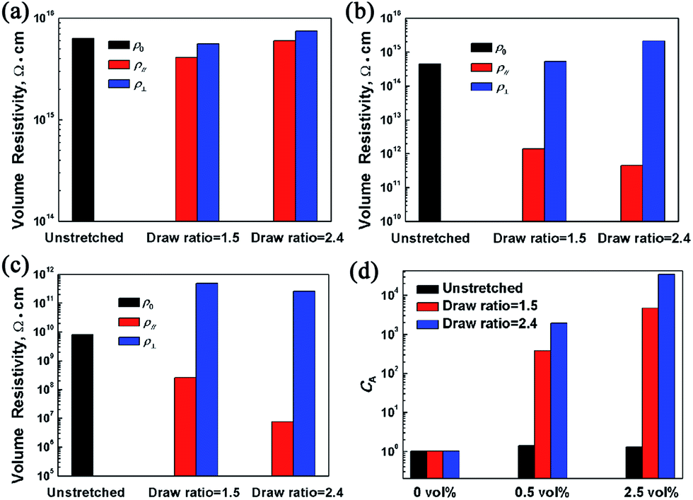 | ||
| Fig. 9 Effect of draw ratio on the anisotropic electrical resistivity of PP/PMMA/graphene nanocomposites with different graphene loadings: (a), (b), and (c) show the electrical resistivity of nanocomposites filled with graphene of 0, 0.5 vol%, and 2.5 vol%, respectively. (d) Shows the anisotropic coefficient (CA) in electrical resistivity of the PP/PMMA/graphene nanocomposites under different draw ratios. | ||
A coefficient CA, which is defined as following, is introduced to characterize the anisotropy quantitatively.
| CA = ρ⊥/ρ∥ | (1) |
As shown in Fig. 9d, a CA as high as 3.5 × 10⁴ was achieved for the PP/PMMA/graphene with 2.5 vol% of graphene loadings under the draw ratio of 2.4. It should be noted that the ρ∥ of this sample was dramatically decreased to 7.5 × 10⁶ Ω cm, which is about five orders of magnitude lower than the ρ0 under its un-stretched state. The results also confirm that high draw ratio is conducive to enhance the anisotropy in electrical conductivity of PP/PMMA/graphene nanocomposites, though the rising trend is lagged as the draw ratio increases from 1.5 to 2.4.
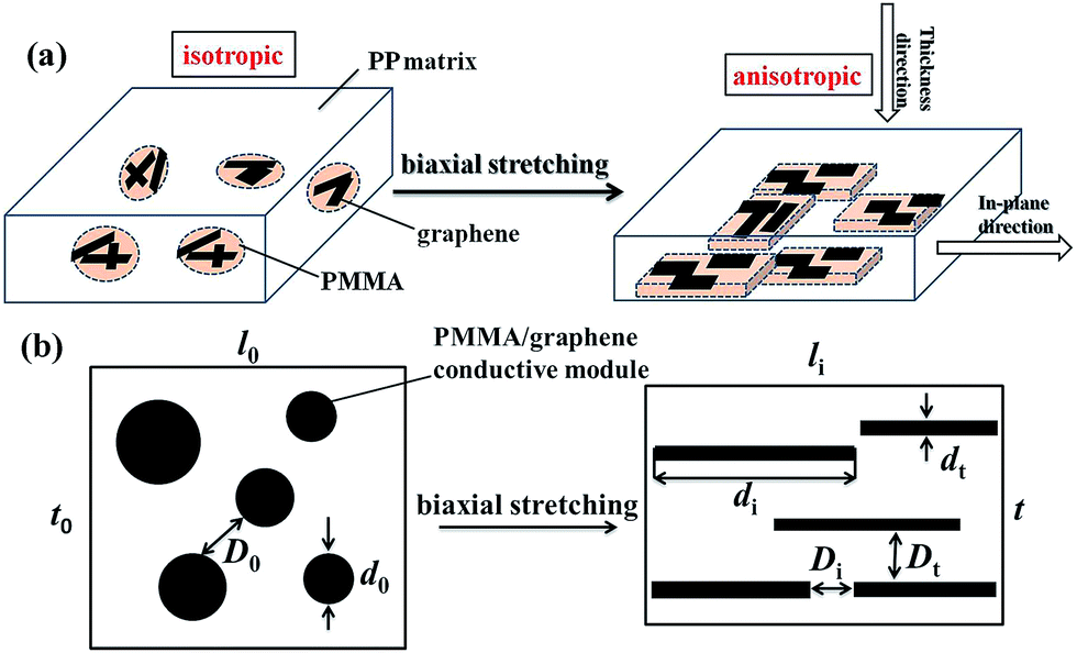
The mechanisms of the biaxial stretching induced morphological transformation and the anisotropic performance of PP/PMMA/graphene nanocomposites are simply discussed. As depicted in Fig. 10, graphene is randomly distributed in PMMA phase and the morphology of PMMA/graphene is bead-like before stretching. In this case, the PP/PMMA/graphene nanocomposites are isotropic. After biaxial stretching, spherical PMMA phase is transformed to sheet-like phase due to its lower shear modulus than PP under the hot drawing conditions. Graphene nanosheets are also dragged by the PMMA chains which results in the orientation along the stretching direction. Consequently, the orientation of PMMA and graphene will give rise to the anisotropy of PP/PMMA/graphene nanocomposites between the in-plane direction and the thickness direction.
 | ||
| Fig. 10 (a) Schematic description of the morphology transformation of PP/PMMA/graphene nanocomposites during the biaxial stretching; (b) is a sectional view of (a). | ||
Fig. 10b gives a sectional view of the PP/PMMA/graphene nanocomposite. PMMA/graphene can be regarded as small conductive modules randomly dispersed in PP matrix. The average diameter of PMMA/graphene particles and the average inter-particle distance among them are defined as d0 and D0, respectively. After biaxial stretching, d0 is divided into two parameters, namely the in-plane direction length (di) and the thickness (dt) of the sheet phase. The di of PMMA/graphene conductive modules is much higher than d0, which results in a large aspect ratio (di/dt). At the same time, the average distance between PMMA/graphene conductive modules in the in-plane direction (Di = D0 + d0 − di) is greatly shortened. In contrast, the average distance between PMMA/graphene modules (Dt = D0 + d0 − dt) exhibits an increase. This opposite trend in the average inter-particle distance between the in-plane direction and the thickness direction should be responsible for the anisotropy in electrical resistivity.
The electrical resistivity can be easily converted into conductivity. For the PP/PMMA/graphene nanocomposites, the conductivity in the in-plane direction is 1.3 × 10⁻⁵ S m−1 with only 2.5 vol% of graphene loading. The anisotropy coefficient of conductivity in the in-plane direction to the thickness direction remains 3.5 × 10⁴. These values are comparable to those anisotropic conductive composite films widely reported in literature by aligning carbon black, carbon nanotube, and graphene.29–31 In present work, the alignment of graphene was induced by the flow of PMMA melt. Considering the graphene nanosheets and PMMA are physically mixed and the intermolecular interactions are still relatively weak, one can expect that the orientation degree of graphene would be further enhanced by chemically grafting PMMA chains onto graphene.32 Furthermore, the alignment direction of graphene might be selectively modulated, rather than the common in-plane orientation, by the combination of optical-field and shear force-field after introducing photo-active polymer chains onto the graphene surface.33–37 Research towards the vertical alignment of graphene in polymer matrix along this approach is on the way.
Conclusions
PP/PMMA/graphene nanocomposites with graphene highly oriented in in-plane direction were fabricated through biaxial stretching in this work. The effect of draw ratio of biaxial stretching on the morphological transformation and the anisotropic performance of PP/PMMA/graphene nanocomposites was investigated. Graphene nanosheets were firstly blended with PMMA and then mixed into PP matrix. Throughout the nanocomposites, graphene nanosheets were confined to selectively disperse in PMMA phase. The optimized hot drawing temperature was 150 °C for PP/PMMA/graphene nanocomposites to realize the orientation of graphene. The morphology of PMMA and distribution of graphene were greatly changed by the biaxial stretching. The PMMA sheets were formed in PP matrix after biaxial stretching. At the same time, the distribution of graphene nanosheets changed from a random state to a highly oriented state along the stretching direction. The incorporation of graphene could enhance the Tg of PMMA while had little effect on the Tm of PP. Both of the Tg of PMMA and the Tm of PP were enhanced after biaxial stretching. Furthermore, both of the storage modulus and the electrical conductivity in the in-plane direction of PP/PMMA/graphene nanocomposites were increased with the draw ratios. A great anisotropic coefficient as high as 35000 in electrical conductivity was achieved by stretching for such PP/PMMA/graphene nanocomposites.
Acknowledgements
Financial supports from Beijing Natural Science Foundation (2142023), National Basic Research Program of China (2014CB239505), National Natural Science Foundation of China (21574012), and Beijing Municipal Commission of Education (km2015100120095) are gratefully acknowledged.References
- K. S. Novoselov, A. K. Geim, S. V. Morozov, D. Jiang, Y. Zhang, S. V. Dubonos, I. V. Grigorieva and A. A. Firsov, Science, 2004, 306, 666–669 CrossRef CAS PubMed.
- O. C. Compton and S. B. T. Nguyen, Small, 2010, 6, 711–723 CrossRef CAS PubMed.
- S. Cheng, X. Chen, Y. G. Hsuan and C. Y. Li, Macromolecules, 2012, 45, 993–1000 CrossRef CAS.
- M. C. Hsiao, S. H. Liao, M. Y. Yen, C. C. Teng, S. H. Lee, N. W. Pu, C. A. Wang, Y. Sung, M. D. Ger, C. C. M. Ma and M. H. Hsiao, J. Mater. Chem., 2010, 20, 8496–8505 RSC.
- M. A. Rafiee, J. Rafiee, Z. Wang, H. Song, Z. Z. Yu and N. Koratkar, ACS Nano, 2009, 3, 3884–3890 CrossRef CAS PubMed.
- Q. Z. Liang, X. X. Yao, W. Wang, Y. Liu and C. P. Wong, ACS Nano, 2011, 5, 2392–2401 CrossRef CAS PubMed.
- J. L. Vickery, A. J. Patil and S. Mann, Adv. Mater., 2009, 21, 2180–2184 CrossRef CAS.
- J. Wang, X. Zhao, J. Li, X. Kuang, Y. Fan, G. Wei and Z. Su, ACS Macro Lett., 2014, 3, 529–533 CrossRef CAS.
- D. D. Kulkarni, I. Choi, S. S. Singamaneni and V. V. Tsukruk, ACS Nano, 2010, 4, 4667–4676 CrossRef CAS PubMed.
- N. Yousefi, M. M. Gudarzi, Q. Zheng, S. H. Aboutalebi, F. Sharif and J. K. Kim, J. Mater. Chem., 2012, 22, 12709–12717 RSC.
- S. Ansari, A. Kelarakis and L. Estevez, Small, 2010, 6, 205–209 CrossRef CAS PubMed.
- M. K. Shin, B. Lee, S. H. Kim, J. A. Lee, G. M. Spinks, S. Gambhir, G. G. Wallace, M. E. Kozlov, R. H. Baughman and S. J. Kim, Nat. Commun., 2012, 3, 650 CrossRef PubMed.
- S. H. Tabatabaei, P. J. Carreau and A. Ajji, J. Membr. Sci., 2008, 325, 772–782 CrossRef CAS.
- J. Smook and J. Pennings, Colloid Polym. Sci., 1984, 262, 712–722 CAS.
- H. X. Tang, Y. R. Lin and H. A. Sodano, Adv. Energy Mater., 2012, 2, 469–476 CrossRef CAS.
- J. B. Shen, M. F. Champagne, R. Gendron and S. Y. Guo, Eur. Polym. J., 2012, 48, 930–939 CrossRef CAS.
- J. B. Shen, M. F. Champagne, Z. Yang, Q. Yu, R. Gendron and S. Guo, Composites, Part A, 2012, 43, 1448–1453 CrossRef CAS.
- S. N. Leung, M. O. Khan, H. Naguib and F. Dawson, Appl. Phys. Lett., 2014, 104, 081904 CrossRef.
- W. L. Gao, Y. Zheng, J. B. Shen and S. Y. Guo, ACS Appl. Mater. Interfaces, 2015, 7, 1541–1549 CAS.
- X. G. Li, G. B. McKenna, G. Miquelard-Garnier, A. Guinault, C. Sollogoub, G. Regnier and A. Rozanski, Polymer, 2014, 55, 248–257 CrossRef CAS.
- K. M. F. Shahil and A. A. Balandin, Nano Lett., 2012, 12, 861–867 CrossRef CAS PubMed.
- P. Kumar, S. Yu, F. Shahzad, S. M. Hong and Y. H. Kim, Carbon, 2016, 101, 120–128 CrossRef CAS.
- F. Xiang, D. Parviz, T. M. Givens, T. Ping and E. M. Davis, Adv. Funct. Mater., 2016, 26, 2143–2149 CrossRef CAS.
- C. Y. Wan and B. Q. Chen, J. Mater. Chem., 2012, 22, 3637–3646 RSC.
- W. S. Hummers and R. E. Offeman, J. Am. Chem. Soc., 1958, 80, 1339 CrossRef CAS.
- S. Stankovich, D. A. Dikin, R. D. Piner, K. A. Kohlhaas, A. Kleinhammes, Y. Jia, Y. Wu, S. B. T. Nguyen and R. S. Ruoff, Carbon, 2007, 45, 1558–1565 CrossRef CAS.
- T. Szabo, O. Berkesi, P. Forgo, K. Josepovits, Y. Sanakis, D. Petridis and I. Dekany, Chem. Mater., 2006, 18, 2740–2749 CrossRef CAS.
- X. W. Zhao and L. Ye, Mater. Sci. Eng., A, 2011, 528, 4585–4591 CrossRef.
- P. Kueseng, P. Sae-oui, C. Sirisinha, K. I. Jacob and N. Rattanasom, Polym. Test., 2013, 32, 1229–1236 CrossRef CAS.
- M. Liu, Y. Du, Y. E. Miao, Q. Ding, S. He, W. W. Tjiu, J. Pan and T. Liu, Nanoscale, 2015, 7, 1037–1046 RSC.
- J. Huang, J. Xu, Y. Sheng, Y. Zhu, W. Jiang, D. Xu, Q. Tang and X. Nie, Macromol. Mater. Eng., 2016, 301, 743–749 CrossRef CAS.
- D. Wang, G. Ye, X. Wang and X. Wang, Adv. Mater., 2011, 23, 1122–1125 CrossRef CAS PubMed.
- Y. He, W. He, D. Liu, T. Gu, R. Wei and X. Wang, Polym. Chem., 2013, 4, 402–406 RSC.
- Y. He, Y. Zhu, Z. Chen, W. He and X. Wang, Chem. Commun., 2013, 49, 5556–5558 RSC.
- J. Wang, S. Wang, Y. Zhou, X. Wang and Y. He, ACS Appl. Mater. Interfaces, 2015, 7, 16889–16895 CAS.
- J. Wang, Y. Zhou, X. Wang and Y. He, RSC Adv., 2015, 5, 9476–9481 RSC.
- R. Wei, X. Wang and Y. He, Eur. Polym. J., 2015, 69, 584–591 CrossRef CAS.
Footnote |
| † Current address: Department of Electrical Engineering, Tsinghua University, Beijing 100084, China. |
| This journal is © The Royal Society of Chemistry 2017 |