
 Open Access Article
 This Open Access Article is licensed under a
 Creative Commons Attribution 3.0 Unported Licence
Reduced graphene oxide (RGO) enriched polymer network for highly-enhanced electro-optic performance of a liquid crystalline blue phase†
MinSu Kim‡§
 ab,
R. K. Mishra‡a,
Ramesh Mandaa,
G. Muralia,
Tae-Hyung Kimc,
Myong-Hoon Leec,
Minhee Yund,
Sudarshan Kundue,
Byoung-Suhk Kimf and
Seung Hee Lee*a
ab,
R. K. Mishra‡a,
Ramesh Mandaa,
G. Muralia,
Tae-Hyung Kimc,
Myong-Hoon Leec,
Minhee Yund,
Sudarshan Kundue,
Byoung-Suhk Kimf and
Seung Hee Lee*a
aApplied Materials Institute for BIN Convergence, Department of BIN Convergence Technology, Department of Polymer-Nano Science and Technology, Chonbuk National University, Jeonju, Jeonbuk 561-756, Korea. E-mail: lsh1@chonbuk.ac.kr; Tel: +82-63-270-2343
bLiquid Crystal Institute, Kent State University, Kent, OH 44242, USA
cGraduate School of Flexible & Printable Electronics Engineering, Chonbuk National University, Jeonju, Jeonbuk 561-756, Korea
dDepartment of Electrical and Computer Engineering, Swanson School of Engineering, University of Pittsburgh, Pittsburgh, PA 15261, USA
eDepartment of BIN Convergence Technology, Chonbuk National University, Jeonju, Jeonbuk 561-756, Korea
fDepartment of Organic Materials & Fiber Engineering, Department of BIN Convergence Technology, Chonbuk National University, Jeonju, Jeonbuk 561-756, Korea
First published on 15th March 2017
Abstract
The excellent physical and chemical properties of graphene have been extensively studied for both scientific interest and novel applications in devices, such as organic photovoltaics, fuel cells, biosensors, and display devices. One of its excellent two-dimensional electric properties is its high electron transporting capability which gives enormous possibility for the performance enhancement of numerous electronic devices. Herein, we demonstrate the record-breaking electro-optic performance of a polymer-stabilized liquid crystalline blue phase using a reduced graphene oxide (RGO) enriched polymer network, which not only enhances the conductivity in the system but also provides counter-benzene-rings to liquid crystalline molecules for strong π–π interaction. It reduces the operation voltage (∼32%), response time (∼51%) and hysteresis (∼53%) compared to that of a conventional polymer-stabilized BPLC, and thereby possibly contributes to novel electro-optic device applications.
Introduction
Graphene, which is a monolayer of carbon atoms tightly packed into honeycomb lattices, is the first theoretical and experimental example of a truly two-dimensional (2D) nanomaterial. Substantial scientific studies are widely devoted to graphene due to its excellent chemical and physical characteristics, such as crystallographic quality, low resistivity, high chemical stability, good optical transmittance, ballistic electron transportation and excellent mechanical strength.1,2 Since the successful synthesis of graphene oxide3 and reduced graphene oxide (RGO),4 such excellent properties are promising to realize ideal optically transparent conductors and numerous vital applications in devices including organic photovoltaics, biosensors, supercapacitors, fuel cells, display devices and nano-hybrid reinforcement.5–18 In addition to the number of well-known applications, one promising approach for organic electronics is graphene-enriched polymer composites including nanostructured polymer matrices.19,20Liquid crystals (LCs) are one of the most widely used electro-optic materials. The LC and polymer composite is well-known as LC droplets dispersed in a polymer matrix, or the so called polymer-dispersed liquid crystal (PDLC) for light shutters, smart windows, and transparent displays.21 In the last decade, the blue phase liquid crystal (BPLC) has been one of the fascinating candidates for next generation display applications because of its unique electro-optic, photonic properties and fast response time, which is enabled by polymer-stabilization.22 The structural property of the BP is based on 3D structured fluids, which are in a thermodynamically stable state with a sharp energetic balance between elasticity and defects.23,24 At sufficiently high-chirality, the double-twist formation becomes even in a low-energy state and thereby, is stabilized by the 3D self-assembly of the double-twist cylinder (DTC) and disclinations. By photo-polymerization, a polymer network is generated in the disclinations by pre-mixed monomers, and it compensates the energy cost to stabilize the phase by more than 80 K.25,26 Such polymer-stabilized (PS) BP has been of substantial interest in condensed matter physics, nanotechnology, and fast-response light modulators including display device applications. However, there are critical shortcomings, such as high-operation voltage and electro-optic hysteresis, although its fast-response and optical isotropy can be huge advantages.22,25–32 In addition to the many efforts to reduce the operation voltage by adjusting electrode structures,27,28,30,31 recently, a report demonstrated that mixing small amount of a polyaniline functionalized graphene oxide (G-PANI) can effectively enhance the operation voltage of PSBP.19 In this way, additional processes of chemical treatments are required to produce G-PANI.
Herein, we propose a novel RGO enriched PSBP using a polymerizable chiral agent. General steps are required to produce the RGO in this way, keeping the fabrication process relatively simpler than using G-PANI. First, the conductivity of the system can be enhanced by the RGO additive. Second, owing to the polymerizable chiral agent in the prepolymer mixture, a polymer network can be generated not only in disclination of BP but also inside the DTCs, giving rise to a relatively rigid polymer network. Third, it is known that ionic impurities can be trapped by the RGO–polymer composite,33,34 and thus the ionic effect would be suppressed. Finally, large numbers of counter benzene rings, against the benzene rings in LC, can be provided by RGO with respect to the polymer network intensifying π–π interaction. Therefore, we expect that the anchoring strength between the LC and RGO–polymer composite would be greatly enhanced [Fig. 1].
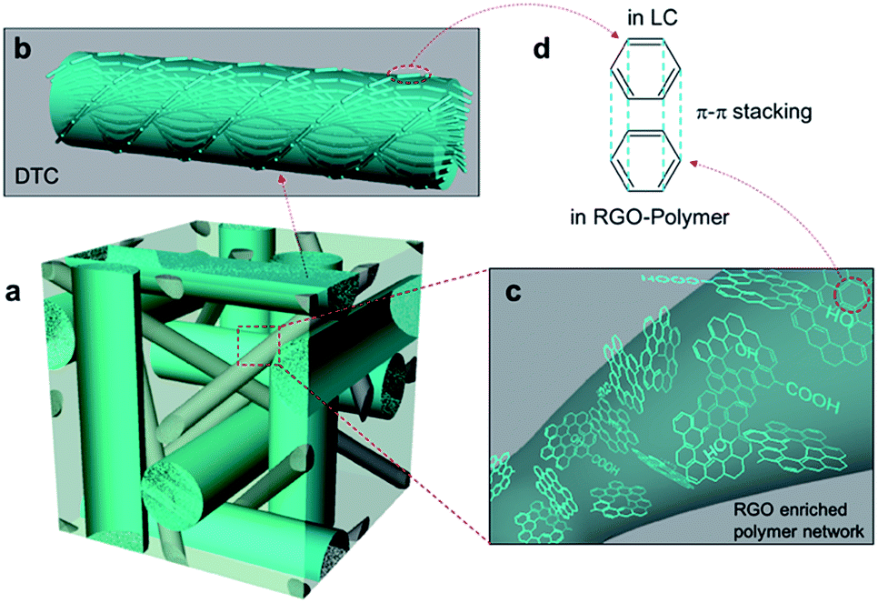 | ||
| Fig. 1 Schematic of the RGO enriched PSBP. (a) PSBP lattice with RGO–polymer. (b) Double-twist cylinder. (c) RGO–polymer network. (d) π–π interaction between LC and RGO–polymer. | ||
Results and discussion
After photo-polymerization of the BP (72 °C) on the PSBP-RGO-0.05 sample, the BP existed over ∼11 °C (83–71 °C) [Fig. 2], whereas it was ∼2 °C before the polymer-stabilization. Although the stabilized temperature range is relatively narrower because the polymer network is formed not only in the disclinations but also inside the DTCs in the lattice by combination of RM-257 and the polymerizable chiral agent, the range could be extended by additional isometric reactive monomers, as reported in several previous studies.22,25 In order to verify the effect of the RGO–polymer composite, one can compare the relative values of the electro-optic properties with and without RGO, that is, between PSBP and PSBP-RGO. Thus, the static and dynamic electro-optic properties were measured by voltage-dependent transmittance [Fig. 3(a)] and time-dependent transmittance [Fig. 3(b)].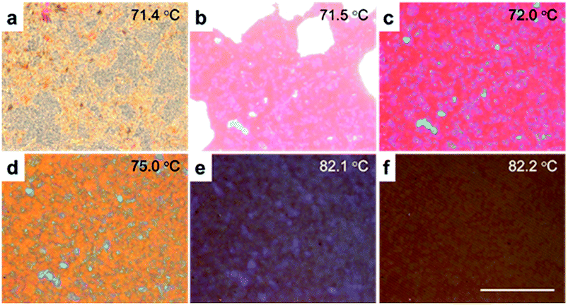 | ||
| Fig. 2 POM images of the PSBP-RGO-0.05 cell at (a) 71.4 °C, (b) 71.5 °C, (c) 72.0 °C, (d) 75.0 °C, (e) 82.1 °C and (f) 82.2 °C. Scale bar is 50 μm. | ||
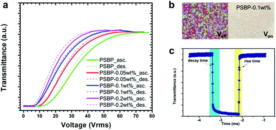 | ||
| Fig. 3 Measured (a) V–T curves (solid: ascending; dotted: descending), (b) POM images in the Voff and Von states at Vop = 48 Vrms, and (c) the rise and decay times of the PSBP-RGO-0.1 cell at 74 °C. | ||
Furthermore, the threshold, Vth, operation voltage, Vop, response time and hysteresis of all the samples are shown in Table 1. As expected,19 the operation voltage tends to be reduced as the concentration of RGO increases, and with 0.2 wt% RGO, the Vth and Vop are reduced by 45% and 31.7%, respectively. In addition to the rise time, the decay time implies a pure interaction between the LC and RGO–polymer when removing the applied voltage. Although the measured decay time is relatively faster (less than sub-milliseconds) due to the measurement at high-temperature (74 °C), the comparison between PSBP and PSBP-RGO fairly demonstrates how RGO influences the electro-optics. The decay time of PSBP-RGO-0.05 is reduced by ∼26% compared to PSBP, and that of PSBP-RGO-0.1 is even further reduced by ∼51%. The hysteresis is defined as H = [(Vasc − Vdes)/Vp] × 100%, where Vasc and Vdes are half of the peak voltages Vp in ascending and descending, respectively.25 Again, comparing PSBP-RGO-0.05 and PSBP, the hysteresis drops by ∼53% owing to the RGO–polymer composite.
| Electro-optics | Vth [Vrms] | Vop [Vrms] | Decay time [μs] | Hysteresis [%] |
|---|---|---|---|---|
| a The approximate degree of difference when RGO is mixed in PSBP in the parenthesis. | ||||
| PSBP | 16 | 60 | 77 | 2.98 |
| PSBP-RGO-0.05 | 12 (25%)a | 53 (12%) | 57 (26%) | 1.41 (53%) |
| PSBP-RGO-0.1 | 9.5 (41%) | 48 (20%) | 38 (51%) | 1.53 (49%) |
| PSBP-RGO-0.2 | 8.8 (45%) | 41 (32%) | 142 (−84%) | 3.17 (−6%) |
Comparing Fig. 4(a) and (b), it is observed that the electro-optic properties rely on different regimes, that is, a linear dependence on the Vth and Vop and non-linear dependence for the decay time and hysteresis. This result is partially consistent with the previous report in ref. 19 which utilized G-PANI. In the previous study, Vop (∼19%) was reduced by 1 wt% of G-PANI (but when the G-PANI concentration range was 0.05–0.5 wt%, it increased), whereas it was ∼32% reduced by only 0.2 wt% RGO in our study. The decay time and hysteresis in that previous study become significant by increasing the G-PANI concentration higher than 0.5 wt% (but to similar degree when the G-PANI concentration was below 0.5 wt%), whereas they reduced with 0.05 wt% and 0.1 wt% RGO in our study by up to 51% and 53% for the decay time and hysteresis, respectively.
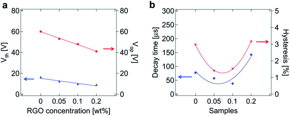 | ||
| Fig. 4 Measured electro-optic characteristics (at 74 °C) of the samples: PSBP, PSBP-RGO-0.05, PSBP-RGO-0.1, PSBP-RGO-0.2. (a) Vth and Vop. (b) Decay time and hysteresis. | ||
When polymerized, again, RGO can coincide with the polymer not only in the disclinations but also within the DTC, and thus conductivity is efficiently enhanced. When the concentration of RGO is higher than 0.1 wt%, the amount of RGO in the polymer network becomes saturated so that the hysteresis and the decay time become more significant than that in the PSBP. When the RGO concentration is 0.05 wt% and 0.1 wt%, the molecules in the RGO–polymer network interact efficiently and tightly with the counter-molecules in BPLC, e.g., π–π interaction between the benzene rings. The Vth and Vop, on the other hand, continuously decrease when the RGO concentration increases because the excess RGO outside the polymer still can contribute to the enhancement of conductivity in the system.
FE-SEM was carried out to identify the polymer network [Fig. 5(a)–(c)]. Due to the chiral reactive monomer, the FE-SEM images of the polymer network show an amorphous structure despite the fact that BPI is stabilized. The inset in Fig. 5(c) shows RGO flakes that aggregate when saturated in the RGO–polymer composite. EDX mapping [Fig. 6(a)–(f)] and EDX spectroscopy [Fig. 6(g)–(i)] were carried out to verify the elements in the RGO–polymer network. The carbon element from RGO and oxygen element from the polymer network are indicated by the greenish blue and green colours in Fig. 6(a–c) and (d–f), respectively. The brightest region in the EDX maps corresponds to the area between the different BP domains (as observed in Fig. 2 and 3(b)), and the polymer network of the FE-SEM images is somewhere inside a domain with a relatively less bright colour. Although the brightness of the colour seems to show a different number of oxygen and RGO flakes exist within the domains and the boundaries, the comparison between the relative amounts in the samples is consistent because the RGO dispersity is the same for each sample.
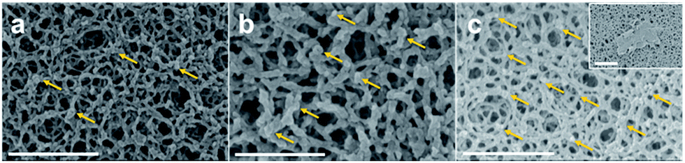 | ||
| Fig. 5 FE-SEM images of the RGO enriched polymer network with concentrations of (a) 0.05 wt%, (b) 0.1 wt%, and (c) 0.2 wt%. Yellow arrows indicate the RGO flakes entangled in the polymer networks. Scale bars are (a, c, and inset in c) 1 μm, and (b) 500 nm. | ||
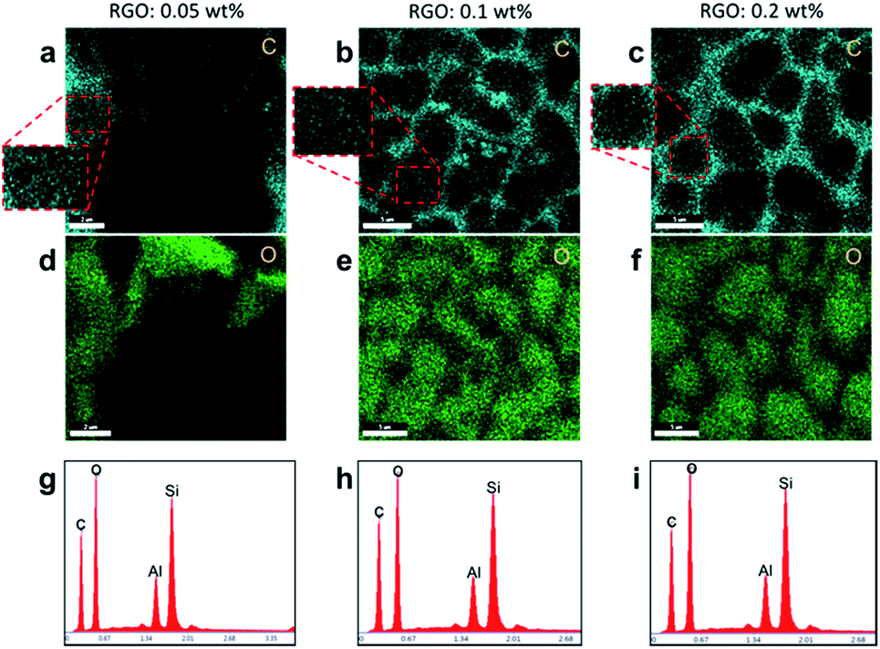 | ||
| Fig. 6 Characterization of the RGO enriched polymer networks with concentrations of (1st column) 0.05 wt%, (2nd column) 0.1 wt%, and (3rd column) 0.2 wt%. EDX maps for (a–c) carbon and (d–f) oxygen with scale bars (a and d) 2 μm and (b, c, e and f) 5 μm. Insets show that carbon exists within the domains with a relatively lower brightness than that at the boundaries. (g–i) EDX spectra. (EDX maps do not correspond to the area in the FE-SEM images in Fig. 5(a)–(c), the silicon peak corresponds to the glass substrate in the cell, and the aluminium peak is from the stage that the substrates are loaded on.) | ||
Experimental
Synthesis of graphene oxide (GO)
GO was prepared from natural graphite (Alfa Aesar) using the modified Hummers method.1,2Reduction of GO by hydrazine hydrate
The prepared GO was reduced by hydrazine hydrate using the following procedure. Firstly, 10 mg of GO was added into 20 ml of DI-water (0.5 mg ml−1) and well sonicated to make good dissolution (brown colour). After that, hydrazine hydrate (35 mmol) was added and the solution was maintained at 100 °C for 16 hours over which the reduced graphene oxide (RGO) gradually precipitated as a black colour. This black precipitate was then filtered by filter paper and washed several times with DI-water and methanol and dried under vacuum to obtain RGO.Characterization of RGO
The prepared RGO was characterized via high-resolution transmission electron microscopy (HR-TEM), selected area electron diffraction (SAED), X-ray diffraction (XRD) and X-ray photoelectron spectroscopy (XPS), as shown in Fig. S9(a)–(e), ESI.†Mixtures
The BPLC mixture consisted of LC (87.8 wt%; MLC-2053, Δε = 42.6 and Δn = 0.235), a chiral dopant (3.3 wt%; SRM-17, helical twisting power (HTP) ∼ 166 μm−1), a photo-polymerizable chiral dopant (1.0 wt%; SRM-3, HTP ∼ 11 μm−1) [Fig. S9(f) and (g), ESI†], reactive diacrylate mesogen (7.4 wt%; RM-257, Δn = 0.179) [Fig. S9(h), ESI†], and a photo-initiator (0.5 wt%; Irgacure-907). This mixture was then mixed with the desired concentrations of RGO (first dispersed in ethanol and then mixed with the BPLC mixture), and each sample is named in Table 1.Cells
After homogeneous mixing, the precursor was heated (at 90 °C) until it reached an isotropic phase and then was injected into a unit cell prepared by two glass substrates: one without an electrode and the other with interdigitated indium-tin-oxide (ITO) electrodes (width and space = 4 μm), in which the cell gap was kept by 10 μm diameter spacers for the electro-optic characterization. Ultraviolet light (40 mW cm−2, wavelength λ = 365 nm) was irradiated on the samples for polymer-stabilization at desired BP temperatures.Characterization of cells
The electro-optic properties were measured by placing the cells between crossed polarizers in a way that the longitudinal direction of the electrodes was 45° to the one of the polarizers and detecting the He–Ne laser light (λ = 633 nm) after obtaining the sample layer. By applying voltage to the cell, the in-plane electric field induced birefringence in the PSBP layer governed by the Kerr effect,22,35,36 and the transmitted light was detected by a photo-detector connected to an oscilloscope (Agilent 33521A). All the samples employed the same fabrication process and measurement, and the results are summarized in Table 1 (also see the ESI†). After all the measurements, the cells were submerged in hexane for a day to wash out the BPLCs, and RGO–polymer network was left for observation by field-emission scanning electron microscopy (FE-SEM) and energy-dispersive X-ray (EDX) spectroscopy.Conclusions
We proposed a reduced graphene oxide (RGO) enriched polymer network that can greatly enhance the electro-optic properties of a polymer-stabilized blue phase (PSBP), such as reduction of the operation voltage, hysteresis and response time in decay. The RGO–polymer composite improves the conductivity of the PSBP and also provides a large number of counter-benzene-rings to liquid crystals for π–π interaction that highly improves the anchoring energy at the interface between them. We believe that this approach contributes not only to the scientific interest in the effect of RGO–polymer composites on the electro-optic characteristics of PSBP, but also to a breakthrough in the performances of PSBP in device applications.Acknowledgements
This research was supported by the Basic Research Laboratory Program (2014R1A4A1008140) through the Ministry of Science, ICT & Future Planning.Notes and references
- A. K. Geim and K. S. Novoselov, Nat. Mater., 2007, 6, 183–191 CrossRef CAS PubMed.
- J. C. Meyer, A. K. Geim, M. I. Katsnelson, K. S. Novoselov, T. J. Booth and S. Roth, Nature, 2007, 446, 60–63 CrossRef CAS PubMed.
- S. Stankovich, R. D. Piner, X. Chen, N. Wu, S. T. Nguyen and R. S. Ruoff, J. Mater. Chem., 2006, 16, 155–158 RSC.
- S. Stankovich, D. A. Dikin, R. D. Piner, K. A. Kohlhaas, A. Kleinhammes, Y. Jia, Y. Wu, S. T. Nguyen and R. S. Ruoff, Carbon, 2007, 45, 1558–1565 CrossRef CAS.
- R. Narayan, J. E. Kim, J. Y. Kim, K. E. Lee and S. O. Kim, Adv. Mater., 2016, 28, 3045–3068 CrossRef CAS PubMed.
- J. E. Kim, T. H. Han, S. H. Lee, J. Y. Kim, C. W. Ahn, J. M. Yun and S. O. Kim, Angew. Chem., Int. Ed., 2011, 50, 3043–3047 CrossRef CAS PubMed.
- J. Y. Kim and S. O. Kim, Nat. Mater., 2014, 13, 325–326 CrossRef CAS PubMed.
- K. E. Lee, J. E. Kim, U. N. Maiti, J. Lim, J. O. Hwang, J. Shim, J. J. Oh, T. Yun and S. O. Kim, ACS Nano, 2014, 8, 9073–9080 CrossRef CAS PubMed.
- H. Park, P. R. Brown, V. Bulović and J. Kong, Nano Lett., 2012, 12, 133–140 CrossRef CAS PubMed.
- R. Raccichini, A. Varzi, S. Passerini and B. Scrosati, Nat. Mater., 2015, 14, 271–279 CrossRef CAS PubMed.
- W. Tie, S. S. Bhattacharyya, Y. J. Lim, S. W. Lee, T. H. Lee, Y. H. Lee and S. H. Lee, Opt. Express, 2013, 21, 19867–19879 CrossRef PubMed.
- J.-H. Ahn and B. H. Hong, Nat. Nanotechnol., 2014, 9, 737–738 CrossRef PubMed.
- S. Y. Jeong, S. Jeong, S. W. Lee, S. T. Kim, D. Kim, H. J. Jeong, J. T. Han, K.-J. Baeg, S. Yang, M. S. Jeong and G.-W. Lee, Sci. Rep., 2015, 5, 11216 CrossRef PubMed.
- C. J. Kirubaharan, K. Santhakumar, G. G. Kumar, N. Senthilkumar and J.-H. Jang, Int. J. Hydrogen Energy, 2015, 40, 13061–13070 CrossRef CAS.
- M. V. Kannan and G. G. Kumar, Biosens. Bioelectron., 2016, 77, 1208–1220 CrossRef CAS PubMed.
- C. Zamora-Ledezma, N. Puech, C. Zakri, E. Grelet, S. E. Moulton, G. G. Wallace, S. Gambhir, C. Blanc, E. Anglaret and P. Poulin, J. Phys. Chem. Lett., 2012, 3, 2425–2430 CrossRef CAS PubMed.
- G. G. Kumar, K. J. Babu, K. S. Nahm and Y. J. Hwang, RSC Adv., 2014, 4, 7944 RSC.
- J. Yuan, A. Luna, W. Neri, C. Zakri, T. Schilling, A. Colin and P. Poulin, Nat. Commun., 2015, 6, 8700 CrossRef CAS PubMed.
- S. Ni, H. Li, S. Li, J. Zhu, J. Tan, X. Sun, C. P. Chen, G. He, D. Wu, K.-C. Lee, C.-C. Lo, A. Lien, J. Lu and Y. Su, J. Mater. Chem. C, 2014, 2, 1730 RSC.
- S. Stankovich, D. A. Dikin, G. H. Dommett, K. M. Kohlhaas, E. J. Zimney, E. A. Stach, R. D. Piner, S. T. Nguyen and R. S. Ruoff, Nature, 2006, 442, 282–286 CrossRef CAS PubMed.
- J. W. Doane, A. Golemme, J. L. West, J. B. Whitehead and B.-G. Wu, Mol. Cryst. Liq. Cryst., 1988, 165, 511–532 CrossRef CAS.
- H. Kikuchi, M. Yokota, Y. Hisakado, H. Yang and T. Kajiyama, Nat. Mater., 2002, 1, 64–68 CrossRef CAS PubMed.
- A. Saupe, Mol. Cryst., 1969, 7, 59–74 CrossRef CAS.
- S. Meiboom, J. P. Sethna, P. W. Anderson and W. F. Brinkman, Phys. Rev. Lett., 1981, 46, 1216–1219 CrossRef CAS.
- M. S. Kim and L.-C. Chien, Soft Matter, 2015, 11, 8013–8018 RSC.
- M. S. Kim, Liquid crystalline amorphous blue phase: tangled topological defects, polymer-stabilization, and device application, Electronic Dissertation, Kent State University, OhioLINK Electronic Theses and Dissertations Center, 2015.
- M. S. Kim, M. Kim, J. H. Jung, K. S. Ha, S. Yoon, E. G. Song, A. K. Srivastava, S.-W. Choi, G.-D. Lee and S. H. Lee, SID Int. Symp. Dig. Tech. Pap., 2009, 40, 1615 CrossRef.
- M. Kim, M. S. Kim, B. G. Kang, M.-K. Kim, S. Yoon, S. H. Lee, Z. Ge, L. Rao, S. Gauza and S.-T. Wu, J. Phys. D: Appl. Phys., 2009, 42, 235502 CrossRef.
- K. M. Chen, S. Gauza, H. Xianyu and S. T. Wu, J. Disp. Technol., 2010, 6, 318–322 CrossRef.
- S. Yoon, M. Kim, M. S. Kim, B. G. Kang, M.-K. Kim, A. K. Srivastava, S. Hee Lee, Z. Ge, L. Rao, S. Gauza and S.-T. Wu, Liq. Cryst., 2010, 37, 201–208 CrossRef CAS.
- M.-K. Kim, M. S. Kim, B. G. Kang, G. H. Yang, A. Mukherjee, S.-W. Kang, H. Lee, S.-T. Shin and S. H. Lee, Mol. Cryst. Liq. Cryst., 2011, 543, 194 CAS.
- R. Manda, M. S. Kim, E. J. Shin, M.-S. Gong, G. Murali, K. Sandeep, M.-H. Lee, J. H. Lee and S. H. Lee, Liq. Cryst., 2016, 1–10 CrossRef.
- A. Rani, J. M. Song, M. J. Lee and J. S. Lee, Appl. Phys. Lett., 2012, 101, 233308 CrossRef.
- R. Islam, A. N. Papathanassiou, R. C. Y. King, J.-F. Brun and F. Roussel, Appl. Phys. Lett., 2015, 107, 53102 CrossRef.
- M. Sato and A. Yoshizawa, Adv. Mater., 2007, 19, 4145–4148 CrossRef CAS.
- A. Yoshizawa, RSC Adv., 2013, 3, 25475 RSC.
Footnotes |
| † Electronic supplementary information (ESI) available: Polarizing optical micrographs and electro-optic characterization of various concentration of RGO. See DOI: 10.1039/c6ra28465e |
| ‡ These authors contributed equally to this work. |
| § Current affiliation: Department of Physics and Astronomy, Johns Hopkins University, Baltimore, MD 21218, USA. |
| This journal is © The Royal Society of Chemistry 2017 |