
 Open Access Article
 This Open Access Article is licensed under a
 Creative Commons Attribution 3.0 Unported Licence
2D quasi-ordered nitrogen and sulfur co-doped carbon materials from ionic liquid as metal-free electrocatalysts for ORR†
Bao-Bing Huanga,
Zhi-Yong Luoa,
Jun-Jun Zhangb and
Zai-Lai Xie *a
*a
aCollege of Chemistry, Fuzhou University, Qishan Campus, 2 Xueyuan Road, Fuzhou 350116, PR China. E-mail: zlxie@fzu.edu.cn
bSchool of Chemistry and Chemical Engineering, Shanghai Jiao Tong University, Shanghai, 200204, P. R. China
First published on 24th March 2017
Abstract
This study explores the novel 2D heteroatom-doped carbon materials for high performance oxygen reduction reaction (ORR). Our strategy involves the ionization of a nitrogen-rich small molecule to prevent its evaporation and subsequent carbonization of the nonvolatile ionic liquids to achieve simultaneous porosity formation and heteroatoms doping. In this context, a nitrogen rich adenine-based ionic liquid possessing a low melting point at 70 °C is synthesized by mixing of commercial adenine and bis(trifluoromethane sulfonimide) (HNTf2). In virtue of protic acid HNTf2, direct carbonization of an ionic liquid results in enhanced carbon yields compared to that of adenine itself. The as-synthesized NC features a uniform 2D quasi ordered nanosheet structure and high surface areas up to 1027 m2 g−1. The nitrogen contents incorporated within the carbon framework can be varied from 37% to 7% as a result of different thermal treatment temperatures from 600 to 1000 °C. Particularly, both nitrogen and sulfur are homogeneously co-doped within the carbon structure as confirmed by EELS maps. The resulting materials show outstanding electrochemical activity towards ORR in alkaline electrolyte, better than most nitrogen doped carbon materials.
Introduction
Fuel cells are regarded as one of the most key technologies to cope with demand for clean energy and sustainable energy conversion.1–3 Oxygen reduction reaction (ORR) is a fundamental reaction involved in fuel cells, where an electrocatalyst is needed to obtain ideal performance or reactivity.4,5 A promising class of catalysts are Pt-based catalysts, which provide a relatively low over-potential and high current density for ORR.6,7 However, the limited reserves and susceptibility to time-dependent drift to ORR of Pt preclude their use for fuel cells.8,9 As a result, the exploration of alternative inexpensive and high performance ORR electrocatalysts is currently being pursed.4,5,10 In the recent past, there have been a set of materials pinpointed around metal-free nitrogen doped carbons (NCs) for ORR electrocatalysis.11–13 NCs usually present higher electron density at the Fermi level, proper basicity and enhanced surface wettability, quite different from those non-doped carbon materials. Recent results demonstrate that a nitrogen doped carbon turns out to be an important family of materials with unprecedented stability, electronic conductivity and electrocatalytic activity for ORR.14–23 Despite of advanced progresses made in the scope of nitrogen doped carbons, their catalytic activity is still far from satisfactory, partly due to their low nitrogen content, low degree of graphitization and less developed porosity. Therefore, it is always highly sought after to search NCs with high heteroatom contents and desirable structure for ORR.Traditionally, nitrogen-containing organic molecules, e.g. ethylenediamine, polyaniline, biomass-derived products, to name a few examples, can be used as precursors for the synthesis of nitrogen-doped carbons.24–28 However, direct carbonization of these compounds usually leads to low carbon yield because of their highly volatilization at high temperature. NH3 gas post-treatment of as-prepared carbons is an alternative method to prepare nitrogen doped carbons. But this process can only introduce limited nitrogen contents and is time consuming.29,30
Direct carbonization of ionic liquids (ILs) is another promising method to synthesize functional carbon materials.31–36 By smart selection of cation and anion, the resultant carbons can be varied in terms of morphology, type of heteroatom doped and porosity.31,37–39 Interestingly, carbon yield of ILs can be significantly improved as a result of strong coulombic interaction between cation and anion. Typical examples include metal-containing and protic ILs, favorable to access high carbon yield.35,36 Moreover, the pyrolysis of ILs often leads to the formation of mesopores channel within carbon framework because of the cleavage and cross-linking of cation or anion moieties.31 This is beneficial for electron and mass transport during heterogeneous reactions. Considering the versatility of ILs, the proper choice of cation or anion could provide a pathway to overcome some difficulties of organic molecules for carbon synthesis. For example, Watanabe et al. have reported that the pyrolysis of an ionic solid p-phenylenediamine bisulfate [pPDA][2HSO4] results in mesoporous carbon materials due to the self-template effect of HSO4 porogen.36 Dai et al. have found that the porosity of ionothermal carbons strongly depends on the selective anions of ILs.31 Many of these ionothermal carbons have already been used as electrode materials for both lithium batteries and supercapacitors,40 whereas, to the best of our knowledge, no studies have been reported on 2D carbon materials directly made from ILs by simply pyrolysis of small molecules for the ORR yet.
Herein, we report a straightforward strategy to synthesize mesoporous carbons with rather high nitrogen contents and carbon yields made from nitrogen-rich nucleobase-ILs, constituted of adenine acting as a cationic component and nitrogen donors and the inorganic acids (HNTf2) serving as an anionic component. The synthesized adenine-based ILs have higher carbonization yield in comparison to adenine upon pyrolysis at elevated temperature to lead to the formation of heteroatom-doped carbons. This is a simple method and does not need the ILs to have cross-linkable groups. The as-synthesized NC features a uniform 2D quasi ordered nanosheet structure, leading to high surface areas up to 1027 m2 g−1. The nitrogen contents were found to be range from 37% to 7% dependent on thermal treated temperature from 600 to 1000 °C. The unique properties of NC with high surface areas, high nitrogen contents and high degree graphitization lend it to the application as high efficient electrocatalysts for ORR.
Results and discussion
Commercial adenine essentially is white fine powder at room temperature with high melting point above 300 °C. By mixing of adenine with HNTf2 in water solution, the protic compound [adenine][HNTf2] was obtained. As shown in Scheme 1, [adenine][HNTf2] presents transparent liquid state at ca. 70 °C. This suggests that large size, low symmetry and charge delocalization of [NTf2]− anion facilitates the formation of low-melting ILs. Differential scanning calorimetry (DSC) curve, shows a pronounced endothermic peak at about 70 °C corresponding to the melting point of [adenine][HNTf2], which is much lower than that of adenine of approximate 350 °C (Fig. S1†). The formation of protic salt is further confirmed by HNMR spectra (Fig. S2†). Both samples display strong resonances assigned to two aromatic hydrogen attached on adenine molecule. The obvious shift to higher number of hydrogen resonance for [adenine][HNTf2] indicates the change of electron density surrounding hydrogen environment, suggesting the complete protonation of adenine.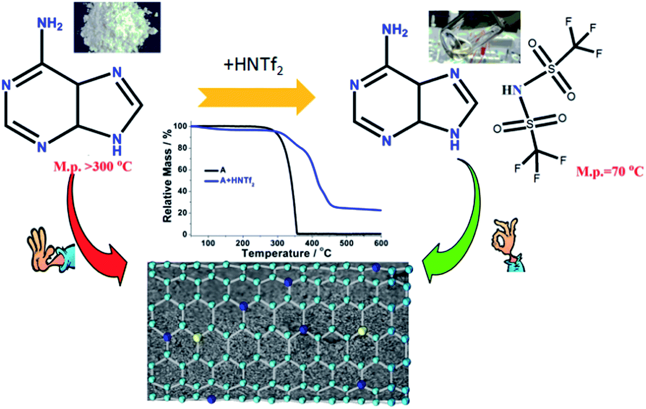 | ||
| Scheme 1 The synthetic routine of adenine based ILs for doped carbon synthesis. | ||
Carbonization yields under pyrolytic condition were elucidated by thermogravimetric analysis (TGA) technique. TGA curves evidence that direct carbonization of adenine leads to negligible carbon yield at elevated temperature. Adenine decomposes in one step with an onset at ca. 273 °C, leaving essentially no carbon residue at ca. 361 °C. It is rather exciting to find the fact that adenine-based ILs exhibit totally different thermal stability. The onset weight loss at 273 °C for the parent adenine is suppressed for [adenine][HNTf2]. The protic adenine yield significant carbon residues and the carbon yield of adenine significantly increases as high as ∼24.5% for [adenine][HNTf2]. The carbonization yields of [adenine][HNTf2] from oven are slightly lower than the corresponding theoretical values calculated on the basis of overall carbon and nitrogen contents of the precursors, likely due to the trace of air in the oven reacting with carbon (Table S1†). The improved thermal stability can be attributed to the protonation effect and the formation of salt, because strong coulombic interaction between cation and anion excludes or at least reduce the weight loss of salt via evaporation prior to thermal decomposition and condensation at high temperature.
The nitrogen sorption behavior of the IL-derived carbons at varied temperature was in detail investigated to clarify the porosity of the resultant carbon materials. As shown in the Fig. 1, both N2 uptake and surface areas of [adenine][HNTf2]-derived carbons steadily rise with increasing of pyrolysis temperature from 600 to 1000 °C. Among these samples, Brunauer–Emmett–Teller (BET) analysis yields the highest surface areas of 548 m2 g−1 for the sample prepared at 1000 °C (Table 1). The increased gas uptake at p/p0 > 0.9 indicates the presence of slit-like pores. The broad hysteresis profile, which does not close upon desorption is a typical case and indicates the presence of swelling effects in irregularly sized mesopore domains. The pore size distribution confirms the presence of hierarchical pores, ranging from 0.5 nm to 10 nm (Fig. 1). Particularly, mesopore volume ascends with the increasing of carbonized temperature presumably due to the structure collapse loss of reactive groups in carbon skeleton including edge of carbon, nitrogen and oxygen. It has to be pointed out that the generation of mesopores without any sacrificial-template or post-activation is of great interest. The developed porosity of the presented carbons is assumed to the unstable NTf2− anions acting as self-porogen for creating microporosity and mesoporosity in the carbon framework, consistent with previously reported ionothermal carbons. In order to obtain the carbon materials with higher surface areas, SiO2 (LUDOX®HS-40) nanoparticles as hard templates were used to develop more porosity, which results in narrow distributed mesoporous structure (A + HNTf2-1000–HS) and generates the high surface areas of 1027 m2 g−1. Interestingly, the surface areas is much higher than previously reported ionothermal carbons made from same SiO2 template.41,42 This is probably due to the generation of a good supply of micropore or interstitial voids by aggregating of thin nanosheet structure.
 | ||
| Fig. 1 N2 sorption isotherm of the ionothermal carbons derived from adenine based ionic liquids. | ||
| Samples | Porosity data | Elemental analysis wt% | |||||
|---|---|---|---|---|---|---|---|
| SBET, [m2 g−1] | Vpore,a [cm3 g−1] | Vmesopore,b [cm3 g−1] | APD [nm] | C | N | Oc | |
| a From total N2 uptake at P/P0 = 0.99.b Mesoporous volume from DFT method.c Calculated. | |||||||
| A + HNTf2-600 | 257 | 0.11 | 0.05 | 2.8 | 38.99 | 37.35 | 20.78 |
| A + HNTf2-800 | 461 | 0.31 | 0.07 | 3.2 | 48.91 | 15.05 | 33.41 |
| A + HNTf2-1000 | 548 | 0.39 | 0.10 | 3.3 | 80.48 | 6.98 | 11.12 |
| A + HNTf2-1000–HS | 1027 | 0.44 | 0.32 | 2.5 | 78.84 | 2.90 | 14.0 |
The elemental analysis shows that NC from thermal treatment at 600 °C contains as high as 37% N contents (Table 1). While, the N concentration of the NCs dramatically decreases from 37% to 7% with increasing pyrolysis temperature. In contrast, the sample prepared with SiO2 template, the N contents is less than 3%, suggested that the small amount of heteroatoms escape from carbon skeleton by hard template process. The depression of N-doping by the SiO2 template has also been reported elsewhere. One of the most promising features of ILs derived carbons is the existence of highly dispersed heteroatoms within entire carbon. Additional X-ray elemental maps show that abundant atoms such as N, S and O are homogeneously dispersed over the entire carbon structure, wherein the nitrogen mainly originated from the cationic structure of precursors, the sulfur from anions solely, while the oxygen from both anions and moistures adsorbed in air, indicating the successful doping of heteroatoms into the carbon skeletons (Fig. 2). Electron energy loss (EELS) spectroscopy was performed to investigated the structural information of carbon materials. The core-level EELS spectrum of the samples shows that the compound is exclusively composed of sp2-hybridized carbon and nitrogen atoms, as indicated by the presence of the electron excitation from the 1s core level to the π* anti-bonding for both elements. The carbon-K ionization edge and nitrogen-K ionization edge show identical near edge structures indicating a similar threefold coordination and electronic environment of the carbon and nitrogen in the carbons. The quantification of the N abundance from the EELS spectra was approximate 16% for [adenine][HNTf2] pyrolized at 800 °C, in accordance with elemental analyses result. EELs data further confirms the sp2-character of the as-prepared NC material.
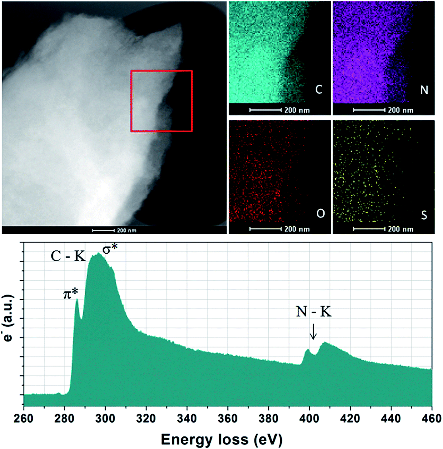 | ||
| Fig. 2 X-ray maps and EELS spectrum of the NC from A + HNTf2-800. | ||
Taking the NCs with developed porosity prepared at 1000 °C as examples, scanning electron microscopic (SEM) images indicate that the sample of A + HNTf2-1000 exhibits a 2D quasi ordered layer-like structure with a mean size in the micrometer range, generating a high degree of interstitial mesoporosity by agglomerated nanosheets (Fig. 3a). Complementary low magnification transmission electron microscopy (TEM) further supports a very homogeneous and interconnected sheet-like morphology. This again implies that the pore structures originated from the voids between the layer-like carbon architecture. Interestingly, the current 2D quasi ordered carbon nanoarchitecture is unprecedentedly distinct from previously reported morphology of ILs derived carbons, indicating that adenine is a potential precursor for 2D carbon materials. The open-type network has more thinner layer sheet, where mesoporosity is clearly observed in S(T)EM images. The sheetlike structure can be further confirmed with atomic force microscopy (AFM) as few-layer stacks. As shown in Fig. S3,† an average thickness value of about 0.7 nm for an area with two overlaid layers is observed. Notably, a thin layer thickness of graphene materials derived from small molecules without any template is unusual. For the sample prepared by using SiO2 as template, carbon material exhibits honeycomb-like continuous nanostructure and the nanosheet structure is still clearly seen. The formation of 2D materials through current method could be assigned to the specific interaction between adenine and protic acid HNTf2. Raman spectroscopy of the A + HNTf2-1000 derived carbon shows two characteristic peaks at 1340 and 1574 cm−1, respectively. Narrow D and G bands indicate partial ordering of the graphite sheets (Fig. S4†).
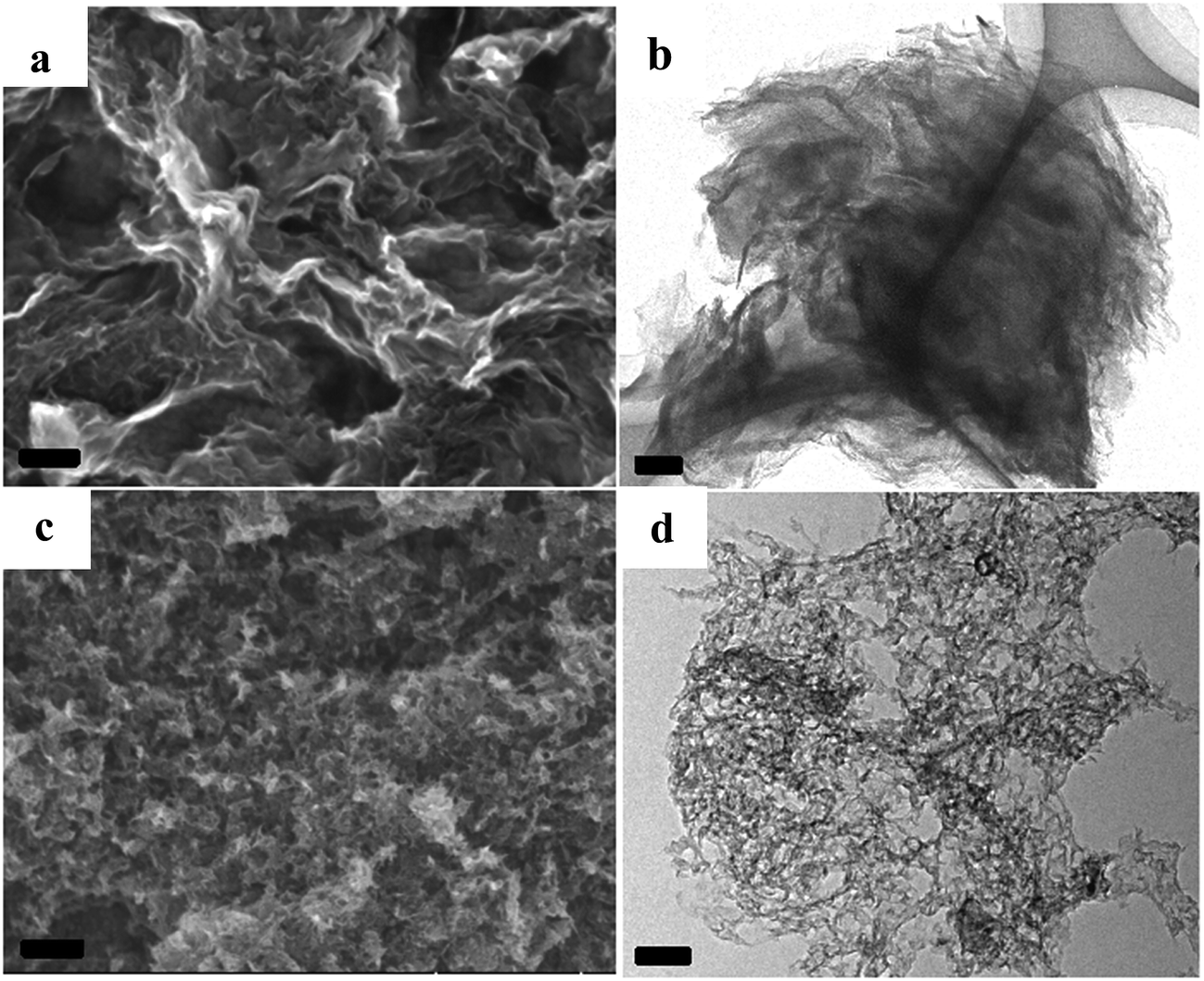 | ||
| Fig. 3 SEM images and TEM images of the NC from [adenine][HNTf2], (a and b): A + HNTf2-1000; (c and d): A + HNTf2-1000–HS, scale bars are 100 nm. | ||
The information of nitrogen-doping was analyzed by X-ray photoelectron spectroscopy (XPS) (Fig. 4). The survey scan spectra from XPS indicate the presence of C 1s, N 1s and O 1s. Additional high resolution N 1s spectra are deconvoluted into five different signals. In details, the lowest binding energy (BE) at 398.3 eV (N1) corresponding to pyridinic N. A peak at 399.2 eV (N2) is related to NH bonds in amides or amines. A feature at 400.1 eV (N3) indicates the presence of pyrrolic N, whereas the BE of 401.1 eV (N4) is typically referred to quaternary N species. The peak at 402.1 eV is related to N–O bonds in pyridine-oxide or nitro groups (N5). Remarkably, the energy peaks N1 and N3 are dominant for both samples. Among others, the carbon derived from HS template generates more N related to amides or amines.
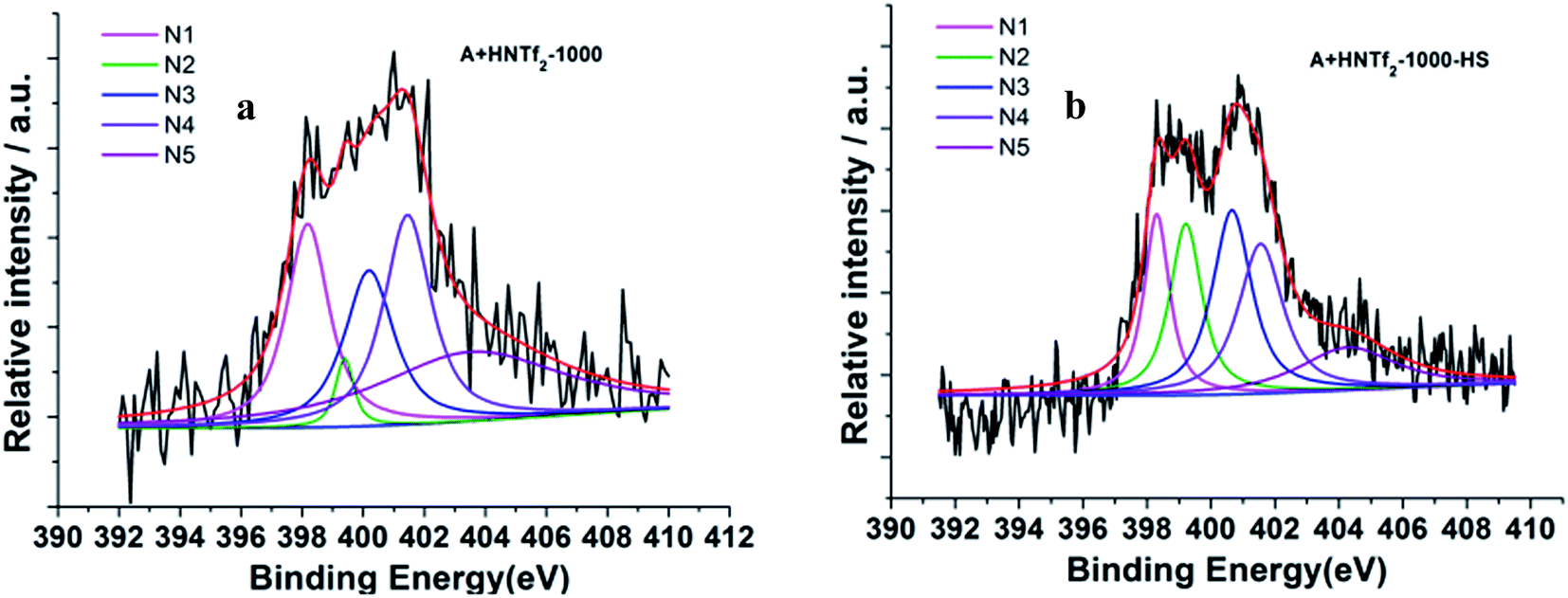 | ||
| Fig. 4 Deconvoluted N 1s photoelectron envelops of the samples (a) A + HNTf2-1000 and (b) A + HNTf2-1000–HS. | ||
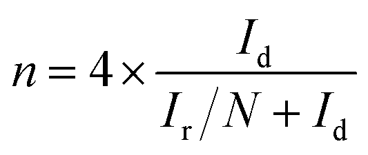
The electrochemical activity of the as-synthesized materials toward ORR was performed in a three-electrode cell, wherein a saturated calomel electrode (SCE) was selected as the reference electrode, a Pt wire as the counter electrode as well as rotating disk electrode (RDE) functioning as the working electrode. All samples were tested in alkaline aqueous media at room temperature, namely, in 0.1 M KOH. The cyclic voltammograms (CVs) were recorded in the O2-saturated solution with a scan rate of 50 mV s−1. Both samples in Fig. 5a give rise to striking oxygen reduction cathodic peaks at about 0.8 V (vs. RHE), indicative of the significant ORR activities. The RDE measurement was conducted to further explore the ORR kinetics. The linear sweep voltammetry polarization curves recorded at a rotating speed of 1600 rpm in 10 mV s−1, exhibit noticeable electrocatalytic performance toward ORR consistent with the CV results. In spite of lower nitrogen contents, the onset potential and plateau current of A + HNTf2-1000–HS were better than the sample of A + HNTf2-1000 in terms of the current density ca. 6 mA cm−2, presumably due to the higher BET surface areas and important micropore distribution which allows more accessible surface active sites. The activities of A + HNTf2-1000–HS were comparable to a commercial 20 wt% Pt/C catalyst in term of the onset and half-wave potential, yet better diffusion-limited current density.
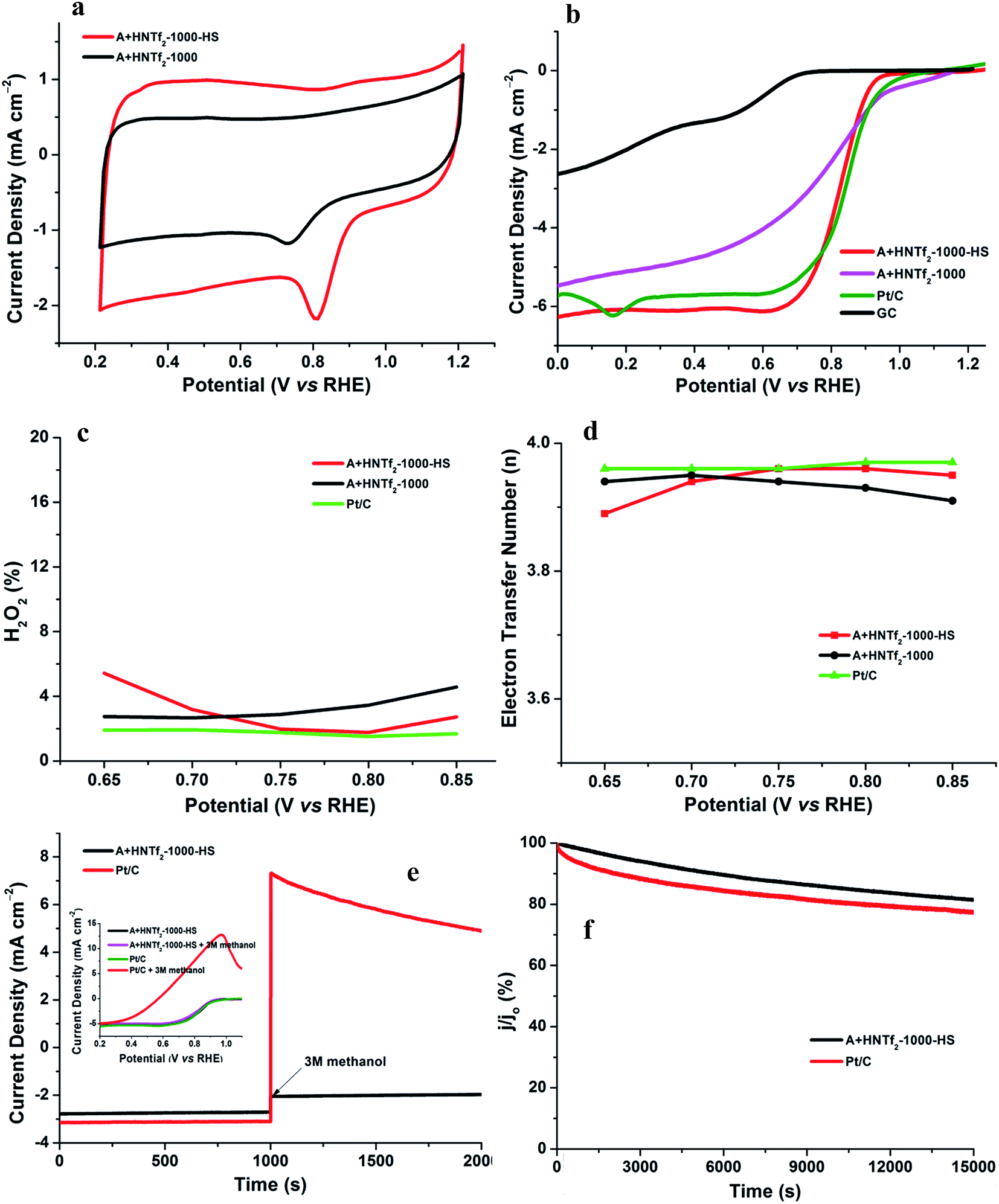 | ||
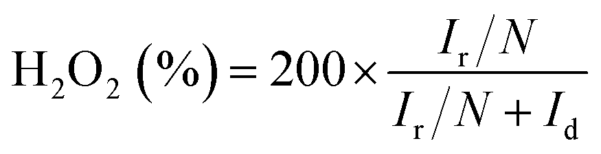
| Fig. 5 Cyclic voltammograms for A + HNTf2-1000 and A + HNTf2-1000–HS in O2-saturated 0.1 M KOH in (a). Comparison of the RDE polarisation curves in O2-saturated 0.1 M KOH at 1600 rpm in (b). The electron transfer number and hydrogen peroxide yield plots at various potentials determined from the corresponding RRDE data in (c and d), respectively. Current–time (i–t) chronoamperometric response at 0.8 V (vs. RHE) in O2-saturated 0.1 M KOH at 1600 rpm, wherein the arrow indicates the addition of methanol. Inset: the corresponding LSV curves of A + HNTf2-1000 and A + HNTf2-1000–HS before and after addition of methanol (3 mol L−1) in (e). i–t response at 0.8 V (vs. RHE) in O2-saturated 0.1 M KOH at 1600 rpm in (f). | ||
The number of electron transfer is evaluated with the rotating ring-disk electrode (RRDE) technology. The calculated electron transfer numbers of both A + HNTf2-1000 and A + HNTf2-1000–HS at different voltages are almost close to four electron process, which forcefully demonstrate the ORR process goes through the beneficial reduction pathway of oxygen to hydroxyl under alkaline conditions. Similarly, hydrogen peroxide yields determined from the corresponding RRDE data both are in ultralow ratios below 6% at various potentials. It is believed that the highly porosity which improve mass transport and diffusion of reactants or products efficiently, coupled with the synergistic activation of N and S codoping vastly facilitate the ORR. Although it is still ambiguous to whether graphitic or pyridinic N species is the most active site toward ORR, pyridinic N and graphitic N structure comparably dominate in our samples such as the A + HNTf2-1000 both contributing to the ORR process, which is rarely seen in other materials with the similar synthesized condition.
In addition, the stability as well as tolerance to methanol are rather crucial factors as to the practical application in fuel cells, wherein the Pt/C catalyst displays imperfect performances. The testing of anti-methanol was conducted at 0.8 V (vs. RHE) in O2-saturated 0.1 M KOH at a rotating rate of 1600 rpm (Fig. 5e and f). As expected, the current direction of Pt/C instantaneously changed in reverse when adding methanol at roughly 1000 s, corresponding to the occurrence of methanol electrooxidation, while A + HNTf2-1000–HS almost kept its original level, which was further confirmed by the changes of LSV curves of A + HNTf2-1000–HS or Pt/C catalyst before and after adding methanol (final concentration of 3 mol L−1). Moreover, current–time (i–t) chronoamperometric response at 0.8 V (vs. RHE) in O2-saturated 0.1 M KOH at 1600 rpm was used to assess the stability of two samples. Remarkably, the current declining tendency of A + HNTf2-1000–HS was slower than Pt/C, keeping at 81.5% and 77.5% after 15![[thin space (1/6-em)]](https://www.rsc.org/images/entities/char_2009.gif) 000 s, respectively. In all, A + HNTf2-1000–HS displays excellent tolerance to methanol and superior durability over the commercial Pt catalyst.
000 s, respectively. In all, A + HNTf2-1000–HS displays excellent tolerance to methanol and superior durability over the commercial Pt catalyst.
Furthermore, the electrocatalytic performance of the current co-doped carbon materials is compared with those of other heteroatom-doped carbon-based ORR electrocatalysts. As depicted in Table 2, the ORR activity of the A + HNTf2-1000–HS is much better than most of other carbons reported elsewhere. Particularly, N–HCH-900 similarly derived from the ionic liquid 3-methyl-1-butylpyridine dicyanamide and SiO2 template displays more two-electron reduction of oxygen, suggesting poor electron transfer to the adsorbed oxygen molecules.41 The morphology of N–HCH-900 and IOC-100 appears hemisphere or opal carbon particles having lower surface areas.42 In contrast, the A + HNTf2-1000–HS presents a porous nanosheet structure possessing higher surface areas and smaller pore size distribution, which allows a high loading of accessible active sites and efficient diffusion for mass transfer. The synthetic protocol presented in this context indeed is efficient to the formation of hierarchical porous carbon nanosheet with a large surface area, a small pore size, and proper nitrogen contents, which are essential for ORR because they impart facile mass transport and provide a high loading of exposed catalytically active sites.
| Catalyst | Electrolyte | ΔEonseta (mV) | ΔJlimitedb (mA cm−2) | n | SBET (m2 g−1) | Ref. |
|---|---|---|---|---|---|---|
| a ΔEonset = Ecat. − EPt/C.b ΔJlimited = |Jcat.| − |JPt/C|. | ||||||
| A + HNTf2-1000–HS | 0.1 M KOH | −17 | −0.33 | 3.94 | 1027 | This work |
| N–HCH-900 | 0.1 M KOH | −86 | −0.13 | 3.14 | 65 | 41 |
| IOC-100 | 0.1 M KOH | −26 | No | >3.5 | 943 | 42 |
| GIL-carbon | 0.1 M KOH | −110 | −0.30 | 3.5–3.8 | 503 | 43 |
| CNT/HDC-1000 | 0.1 M KOH | −56 | −0.48 | 3.8–3.9 | 325 | 15 |
| CNF@NG | 0.1 M KOH | −136 | −0.45 | >3.6 | 206 | 18 |
| S doped C | 0.1 M KOH | −200 | — | 3.4 | 341 | 44 |
Conclusions
Within this study, we have developed a facile, catalyst free, and IL-based approach for the synthesis of mesoporous nitrogen-rich doped carbons. This process is direct carbonization of protic ILs, which enables astonishingly increase of carbon yields. The resultant NCs possess favorable properties such as 2D quasi ordered nanostructures, hierarchical porosity and relatively high surface areas. The nitrogen contents can be easily tuned from 7% to 37% by varying of carbonized temperature. This kind of ionothermal carbons show the outstanding electrochemical activity towards ORR in alkaline electrolyte close to that of commercial Pt/C-catalyst. Such application of ionic liquids provides the strategy to improve carbonization efficiency in the area of ionic liquids as carbon precursors.Experimental section
Sample preparation
[Adenine][HNTf2] was prepared by the following procedures. Briefly, 5 g HNTf2 was mixed with 2.4 g adenine in cold water, subsequent stirring for several hours until the milky mixture turned transparent. The solvent was removed under reduced pressure, followed by drying overnight at 100 °C. The as-prepared [adenine][HNTf2] was placed in ceramic crucibles and subjected to directly carbonization at 600 °C, 800 °C, 1000 °C, respectively, with a heating rate of 10 K min−1 and holding the targeted temperature for 4 h in N2 atmosphere. The obtained samples were denoted as A + HNTf2-600, A + HNTf2-800 and A + HNTf2-1000, respectively, according to the corresponding pyrolytic temperature. As for A + HNTf2-1000–HS, [adenine][HNTf2] was thoroughly mixed with LUDOX®HS-40 based on the weight ratio of 1:2.5 under the stirring-heating condition, then the similar carbonized process at 1000 °C. After carbonization, the obtained composition was etched with a 10% HF solution to remove the silica template and dried, thus got the desired material. All synthesized samples were ground into powders for further analysis.
Characterization
Thermoanalytic analyses were performed with a NETSCH STA449F3 thermobalance setup in N2 atmosphere with a constant gas flow of 50 mL min−1 in a temperature range of 40–600 °C with a heating rate of 10 K min−1. Elemental analysis of C, H, and N was performed by using a Vario EL III CHNOS elemental analyzer. Scanning electron microscopy (SEM) images were acquired on a FEI Nova NanoSEM 230 with Everhard–Thornley secondary electron and in-lens detectors. Transmission Electron Microscopy (TEM) and EELS spectrum were done on a FEI Cs-corrected Titan 80–300 microscope operated at 300 kV with a Gatan energy filter. Nitrogen sorption isotherms were measured at 77 K on a Quadrachrome adsorption instrument (Quantachrome Instruments). Sample was dried at 100 °C for 6 h prior to nitrogen sorption analysis. Atomic force microscopy (AFM) images were obtained with an Agilent 5500 (USA) using a tapping mode.Electrochemical measurements
For the rotating disk electrode (RDE) experiment, a glassy carbon electrode (GCE, d = 4 mm) was pre-polished and rinsed cleanly. 5 mg of the carbon sample was dispersed in the mixture of 0.35 mL deionized water, 0.7 mL ethanol and 0.08 mL Nafion (5 wt%), then sonicated for 1 h to get a homogeneous catalyst ink. Dropping 12.8 μL of the as-prepared ink onto the surface of the GCE and drying in air for testing. All measurements were conducted in the O2-saturated solution. For comparison, the commercial 20 wt% Pt/C catalyst was prepared and measured under the same conditions.With regard to the rotating ring-disk electrode (RRDE) experiment, the ring-disk electrode with a glassy carbon disk (d = 4 mm) and a Pt ring (5 mm inner diameter, 7 mm outer diameter) was served as the working electrode with the same loading of catalyst as the RDE measurement. The ring potential was kept at 0.5 V (vs. SCE). The number of electron transfer is evaluated from the following equations
 | (1) |
 | (2) |
Acknowledgements
The Award Program for Fujian Minjiang Scholar Professorship is acknowledged for financial support. We thank financial support from the National Natural Science Foundation of China (NSFC grant number 21571035). We thank Prof. Xin-Hao Li from SJTU for fruitful discussion and Prof. Meijin Lin from FZU for HNMR measurement.References
- B. C. H. Steele and A. Heinzel, Nature, 2001, 414, 345–352 CrossRef CAS PubMed
.
- R. Bashyam and P. Zelenay, Nature, 2006, 443, 63–66 CrossRef CAS PubMed
- A. Manthiram, A. V. Murugan, A. Sarkar and T. Muraliganth, Energy Environ. Sci., 2008, 1, 621–638 CAS
- X. Ge, A. Sumboja, D. Wuu, T. An, B. Li, F. W. T. Goh, T. S. A. Hor, Y. Zong and Z. Liu, ACS Catal., 2015, 5, 4643–4667 CrossRef CAS
- S. Guo, S. Zhang and S. Sun, Angew. Chem., Int. Ed., 2013, 52, 8526–8544 CrossRef CAS PubMed
- V. Stamenkovic, B. S. Mun, K. J. J. Mayrhofer, P. N. Ross, N. M. Markovic, J. Rossmeisl, J. Greeley and J. K. Norskov, Angew. Chem., Int. Ed., 2006, 45, 2897–2901 CrossRef CAS PubMed
- Y. J. Kang, X. C. Ye, J. Chen, Y. Cai, R. E. Diaz, R. R. Adzic, E. A. Stach and C. B. Murray, J. Am. Chem. Soc., 2013, 135, 42–45 CrossRef CAS PubMed
- J. B. Wu and H. Yang, Acc. Chem. Res., 2013, 46, 1848–1857 CrossRef CAS PubMed
- M. Winter and R. J. Brodd, Chem. Rev., 2004, 104, 4245–4269 CrossRef CAS PubMed
- Z. W. Chen, D. Higgins, A. P. Yu, L. Zhang and J. J. Zhang, Energy Environ. Sci., 2011, 4, 3167–3192 CAS
- K. P. Gong, F. Du, Z. H. Xia, M. Durstock and L. M. Dai, Science, 2009, 323, 760–764 CrossRef CAS PubMed
- Y. G. Li, W. Zhou, H. L. Wang, L. M. Xie, Y. Y. Liang, F. Wei, J. C. Idrobo, S. J. Pennycook and H. J. Dai, Nat. Nanotechnol., 2012, 7, 394–400 CrossRef CAS PubMed
- D.-W. Wang and D. Su, Energy Environ. Sci., 2014, 7, 576 CAS
- W. Yang, T. P. Fellinger and M. Antonietti, J. Am. Chem. Soc., 2011, 133, 206–209 CrossRef CAS PubMed
- Y. J. Sa, C. Park, H. Y. Jeong, S. H. Park, Z. Lee, K. T. Kim, G. G. Park and S. H. Joo, Angew. Chem., Int. Ed., 2014, 53, 4102–4106 CrossRef CAS PubMed
- N. R. Sahraie, J. P. Paraknowitsch, C. Gobel, A. Thomas and P. Strasser, J. Am. Chem. Soc., 2014, 136, 14486–14497 CrossRef PubMed
- Z. Li, G. Li, L. Jiang, J. Li, G. Sun, C. Xia and F. Li, Angew. Chem., Int. Ed., 2015, 54, 1494–1498 CrossRef CAS PubMed
- T. N. Ye, L. B. Lv, X. H. Li, M. Xu and J. S. Chen, Angew. Chem., Int. Ed., 2014, 53, 6905–6909 CrossRef CAS PubMed
- J. Wei, Y. Hu, Y. Liang, B. Kong, J. Zhang, J. Song, Q. Bao, G. P. Simon, S. P. Jiang and H. Wang, Adv. Funct. Mater., 2015, 25, 5768–5777 CrossRef CAS
- L. Lai, J. R. Potts, D. Zhan, L. Wang, C. K. Poh, C. Tang, H. Gong, Z. Shen, J. Lin and R. S. Ruoff, Energy Environ. Sci., 2012, 5, 7936 CAS
- W. Ding, Z. Wei, S. Chen, X. Qi, T. Yang, J. Hu, D. Wang, L. J. Wan, S. F. Alvi and L. Li, Angew. Chem., Int. Ed., 2013, 52, 11755–11759 CrossRef CAS PubMed
- T. Xing, Y. Zheng, L. H. Li, B. C. C. Cowie, D. Gunzelmann, S. Z. Qiao, S. M. Huang and Y. Chen, ACS Nano, 2014, 8, 6856–6862 CrossRef CAS PubMed
- D. H. Guo, R. Shibuya, C. Akiba, S. Saji, T. Kondo and J. Nakamura, Science, 2016, 351, 361–365 CrossRef CAS PubMed
- C. L. Long, D. P. Qi, T. Wei, J. Yan, L. L. Jiang and Z. J. Fan, Adv. Funct. Mater., 2014, 24, 3953–3961 CrossRef CAS
- N. P. Wickramaratne, J. T. Xu, M. Wang, L. Zhu, L. M. Dai and M. Jaroniec, Chem. Mater., 2014, 26, 2820–2828 CrossRef CAS
- L. Zhao, L. Z. Fan, M. Q. Zhou, H. Guan, S. Y. Qiao, M. Antonietti and M. M. Titirici, Adv. Mater., 2010, 22, 5202–5206 CrossRef CAS PubMed
- A. Vinu, P. Srinivasu, D. P. Sawant, T. Mori, K. Ariga, J. S. Chang, S. H. Jhung, V. V. Balasubramanian and Y. K. Hwang, Chem. Mater., 2007, 19, 4367–4372 CrossRef CAS
- G. Wu, N. H. Mack, W. Gao, S. G. Ma, R. Q. Zhong, J. T. Han, J. K. Baldwin and P. Zelenay, ACS Nano, 2012, 6, 9764–9776 CrossRef CAS PubMed
- R. Arrigo, M. Havecker, S. Wrabetz, R. Blume, M. Lerch, J. McGregor, E. P. J. Parrott, J. A. Zeitler, L. F. Gladden, A. Knop-Gericke, R. Schlogl and D. S. Su, J. Am. Chem. Soc., 2010, 132, 9616–9630 CrossRef CAS PubMed
- H. Jin, H. M. Zhang, H. X. Zhong and J. L. Zhang, Energy Environ. Sci., 2011, 4, 3389–3394 CAS
- J. S. Lee, X. Q. Wang, H. M. Luo, G. A. Baker and S. Dai, J. Am. Chem. Soc., 2009, 131, 4596 CrossRef CAS PubMed
- J. P. Paraknowitsch, J. Zhang, D. Su, A. Thomas and M. Antonietti, Adv. Mater., 2010, 22, 87–92 CrossRef CAS PubMed
- J. S. Lee, X. Wang, H. Luo and S. Dai, Adv. Mater., 2010, 22, 1004–1007 CrossRef CAS PubMed
- X. Wang and S. Dai, Angew. Chem., Int. Ed., 2010, 49, 6664–6668 CrossRef CAS PubMed
- J. Yuan, C. Giordano and M. Antonietti, Chem. Mater., 2010, 22, 5003–5012 CrossRef CAS
- S. Zhang, M. S. Miran, A. Ikoma, K. Dokko and M. Watanabe, J. Am. Chem. Soc., 2014, 136, 1690–1693 CrossRef CAS PubMed
- P. F. Fulvio, J. S. Lee, R. T. Mayes, X. Wang, S. M. Mahurin and S. Dai, Phys. Chem. Chem. Phys., 2011, 13, 13486–13491 RSC
- J. P. Paraknowitsch, B. Wienert, Y. Zhang and A. Thomas, Chem.–Eur. J., 2012, 18, 15416–15423 CrossRef CAS PubMed
- J. P. Paraknowitsch, Y. Zhang, B. Wienert and A. Thomas, Chem. Commun., 2013, 49, 1208–1210 RSC
- S. Zhang, K. Dokko and M. Watanabe, Mater. Horiz., 2015, 2, 168–197 RSC
- C. L. Han, J. Wang, Y. T. Gong, X. Xu, H. R. Li and Y. Wang, J. Mater. Chem. A, 2014, 2, 605–609 CAS
- S. G. Zhang, H.-M. Kwon, Z. Li, A. Ikoma, K. R. Dokko and M. Watanabe, ChemElectroChem, 2015, 2, 1080–1085 CrossRef CAS
- Y. Y. She, Z. G. Lu, M. Ni, L. Li and M. K. H. Leung, ACS Appl. Mater. Interfaces, 2015, 7, 7214–7221 CAS
- L. P. Wang, W. S. Jia, X. F. Liu, J. Z. Li and M. M. Titirici, J. Energy Chem., 2016, 25, 566–570 CrossRef
Footnote |
| † Electronic supplementary information (ESI) available. See DOI: 10.1039/c6ra28381k |
| This journal is © The Royal Society of Chemistry 2017 |