 Open Access Article
Zeolitic-imidazole framework thin film-based flexible resistive switching memory†
Myung-Joo Park and
Jang-Sik Lee *
*
Department of Materials Science and Engineering, Pohang University of Science and Technology (POSTECH), Pohang 37673, Korea. E-mail: jangsik@postech.ac.kr
First published on 12th April 2017
Abstract
As some of the organic–inorganic hybrid materials that have been researched actively for decades, metal–organic frameworks (MOFs) have been studied in various fields due to their high chemical tunability and stability. MOFs could be characterized by their various crystal structures and 3-dimensional porous structures, and, by changing the framework, can be useful for applications such as catalysis, chemical sensing, and gas separation. Due to their structural complexity and difficulties in making the desired form of framework, MOFs have not been widely explored in the field of electronic devices. In this work, we designed resistive switching random access memory (ReRAM) by introducing a zeolitic imidazolate framework (ZIF)-8 thin film as the resistive switching layer. ZIF-8 is one of the MOF materials with a sodalite zeolite-type structure, which includes zinc ions and 2-methylimidazole as the metal nodes and organic linkers. ZIF-8 thin film-based ReRAM possesses consistent resistive switching behavior. Synthesis of the ZIF-8 thin film is accomplished using simple solution processes. Characteristics of the thin film were confirmed using X-ray diffraction and scanning-electron microscopy. Its resistive switching properties as well as the mechanical flexibility were tested using flexible memory devices on plastic substrates. The resistive switching behavior of ZIF-8 could be explained by the redox-active nature of its linker molecules, which enables electrons to be transported from one electrode to the other.
Introduction
Metal–organic frameworks (MOFs) are classified as hybrid organic–inorganic materials that are composed of various metal ionic centers and organic molecular linkers. Recently these materials have become attractive for use in various fields because of their structural tunability and chemical stability.1,2 The 3-dimensional (3D) structure of a MOF could be diversely modified by changing the metal and organic components and its composition. By the virtue of their versatility, MOFs with different pore sizes and crystal structures have been adjusted for use in the fields of hydrogen adsorption and separation,3–7 chemical sensors,8,9 luminescence,10,11 and catalysis.12 Moreover, the beneficial traits of MOFs enable MOF materials to be fabricated as MOF thin films for further applications such as in chemical sensors, catalytic coatings, smart membranes, and related nanodevices.13,14 For example, MOF-based sensors, optoelectronic devices15 and memory devices16,17 could be fabricated.In the field of next-generation non-volatile memory, there are various structures and types of memory device including phase change memory, ferroelectric memory, spin transfer torque-magnetic memory, and resistive switching random access memory (ReRAM). ReRAM is one of the next-generation non-volatile memory devices that has attracted much attention due to its fast reading/writing speeds, good scalability, and simple device structures.18 Basically ReRAM devices have a simple metal–insulator–metal (MIM) structure.19 Resistive switching characteristics have been reported in diverse materials systems, including perovskite oxides, chalcogenides, and transition metal oxides.20 Recently, researchers have largely studied hybrid organic–inorganic materials such as metal-halide perovskites and MOFs.16,17,21
In this paper, we suggest a MOF-based resistive switching device utilizing zeolitic imidazolate framework (ZIF)-8 on a flexible polyethylene terephthalate (PET) substrate with a facile fabrication method. ZIF-8 has a sodalite structure with the Si or Al site and O site substituted by zinc ions and 2-methylimidazole molecules, respectively. Synthesis of the ZIF-8 thin film was achieved using a simple solution-based dip coating process. The prepared thin films with 3D frameworks have good crystalline structures on the Au bottom electrode which is coated onto the PET flexible substrates. A ZIF-8 thin layer was stacked in between the 100 nm thick Au and Al thin films used as the bottom and top electrodes. Using this method we could realize the possibility of ZIF-8 to be the active material for resistive switching devices. In addition, employing the flexible substrate proved the mechanical flexibility of the material.
Results and discussion
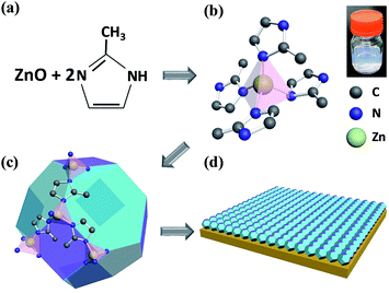
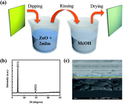
MOFs are constructed using various combinations and proportions of metal ions and organic linkers.22 According to the composition, the crystal structure and pore sizes could be changed.23 ZIF-8, as one of the MOF materials, was chosen for the resistive switching layer in between two electrodes. This material is composed of nodes and linkers.24 Nodes are centered by Zn2+ ions and linked by four 2-methylimidazole molecules as the linker of the whole crystal structure.25 The topology of this material is the same as the topology that could be found in aluminosilicate zeolites (Fig. 1).26 The framework of a zeolite is constructed by tetrahedral Si or Al connected by O atoms.27 Whereas in ZIF-8, the tetrahedral Si or Al is replaced by transition metal atoms and bridging O atoms are substituted by imidazolate linkers. Like zeolites, the framework of ZIFs possesses a regular porous structure and channels that could differentiate based on the molecular class. As shown in Fig. 1a, one zinc ion is combined with two 2-methylimidazole molecules to build a tetrahedral structure, which is shown in Fig. 1b. The inset shows the as-synthesized ZIF-8 stock solution with a cloudy color. Illustrated in Fig. 1c, those tetrahedral topologies were connected together to make the shape of the zeolite type structure, as mentioned above. This structure had large cavities of 11.6 Å in diameter and small pore apertures of 3.4 Å.23,28–30 There are studies about synthesizing ZIF-8 nanocrystals and ZIF-8 thin films onto a substrate using various solvents such as dimethylformamide (DMF), diethylformamide (DEF), or methanol.25 Furthermore there are reported processes to synthesize the desired thin films of MOFs to make them applicable to sensors or electronic devices.31–33 In this paper, we adopted a simple method to synthesize ZIF-8 thin films in the form shown in Fig. 1d.We employed a simple bottom-up fabrication method to deposit the ZIF-8 thin film. It has been previously reported that there are some ways to create MOF thin films, including ZIF-8, with various crystal sizes ranging from micrometers to nanometers.34–37 However, some of those methods are costly and need specialized apparatus. Also it is not easy to synthesize porous supports with precisely controlled thicknesses of films at the micrometer or nanometer scale. In this work, we employed a very simple method to synthesize ZIF-8 thin films. Firstly, ZIF-8 stock solution needs to be prepared prior to immersing a substrate to make thin films. The stock solution is made by mixing zinc methanolic solution and 2-methylimidazolate methanolic solution for a few minutes. A substrate prepared in advance is made of 100 nm of Au thin film deposited on a PET flexible substrate with a 10 nm adhesive layer of Ti in between. Before ZIF-8 thin films are coated onto the substrates, the substrates need to be specially treated with piranha solution to create functional groups on them. After surface treatment with piranha solution, the flexible Au-coated substrate was immersed into the ZIF-8 stock solution made with Zn2+ ion precursor, 2-mIm precursor, and methanol solvent. Dip coating takes 30 min to synthesize the ZIF-8 thin layer and finally, the substrate was rinsed with methanol solution and then dried. The synthesis method is described schematically in Fig. 2a. The structure of the prepared ZIF-8 layer was examined using X-ray diffraction (XRD) measurements and scanning electron microscopy (SEM) (Fig. 2b and c). The XRD pattern of our fabricated ZIF-8 thin film shows (110) orientation and the SEM image shows the ZIF-8 stacked layer of about 200 nm thickness on the Au bottom electrode.
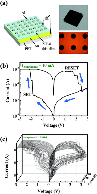
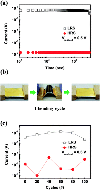
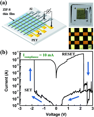
Fig. 3a shows a schematic structure of the ZIF-8 thin layer-adopting resistive switching memory device. The device is composed of an Al top electrode, a ZIF-8 active layer, an Au bottom electrode on a Ti adhesive layer of 10 nm, and a PET flexible substrate. The insets show a photograph and an optical microscope image of the fabricated device. ZIF-8 based ReRAM on the PET flexible substrate showed resistive switching behaviour without any medium with a dipole moment to cause the resistive switching, as shown in Fig. 3b. To prove the programmable memory properties of the flexible Au/ZIF-8/Al device, the I–V characteristics were measured during a DC voltage sweep (0 → −3 → 0 → 3 → 0 V). The device possesses a negative set behavior with a compliance current of 10 mA. The set process indicates the change of resistance states from a high-resistance state (HRS, insulative OFF state) to a low-resistance state (LRS, conductive ON state). During the application of a negative voltage sweep from 0 to −3 V, the set process occurred at −1.9 V. Application of a positive voltage sweep changed the resistance of the ZIF-8 layer from the LRS to HRS (reset process). Additionally, we investigated the I–V characteristics according to the different compliance current conditions (Fig. S1†). The resistive switching properties were measured as the compliance current was reduced from 10−2 A to 10−5 A. The device showed resistive switching behavior for all compliance current levels. Though at some conditions, the I–V curve showed overshoot in the reset process, which means that the current value of the device exceeded the compliance current value. A compliance current of 10−3 A does not cause overshoot in the device. Fig. 3c shows repeated resistive switching cycles over several cycles. Reproducible and reliable bipolar resistive switching properties were observed in the ZIF-8-based ReRAM device. Also its data retention and mechanical flexibility are assessed (Fig. 4a). During data retention measurements, a continuous reading bias of 0.5 V was applied to check the changes in current values with time. Each resistance state is stably maintained for up to 4000 s with almost no change. Fig. 4b shows one cycle of the bending procedure which was employed in this experiment. The bending radius of each cycle is 1.35 cm. Fig. 4c shows the resultant bending stability from the bending test over 100 bending cycles. Each state was read with the application of a reading bias of 0.5 V. There is some fluctuation in each state according to the bending cycles, but the ON/OFF ratio is well maintained during 100 bending cycles. These results imply that ZIF-8 shows bipolar resistive switching behavior with not only electrical reliability but also mechanical stability. In this paper, resistive switching memory characteristics were obtained with the ZIF-8 active layer synthesized by a dip coating method. The conduction mechanism of each resistance state, LRS and HRS, in the ZIF-8 layer could be explained by the redox-active behavior of the organic linkers, 2-mIms. These molecules are made of an imidazole ring and one methyl group between two non-adjacent nitrogen atoms. Those imidazole rings are redox-active molecules which are aromatic rings with π-electrons. It was previously reported that resistive switching properties arose from the redox-active nature of the organic molecules in MOF materials.16 The mechanism of the resistive switching behavior is suggested and schematically demonstrated in Fig. S2.† When the electric field is applied onto the Au/ZIF-8/Al structured device, Zn2+ ions at the localized node site act as hopping sites between organics, as shown in Fig. 5a. At a set voltage, Zn2+ could be delocalized from the 2-mIm linkers to be reduced to Zn atoms (Fig. S2b†). Disconnected from Zn2+, the left bond of N atoms in the 2-mIm molecules would be electrically connected to produce a conduction path. Electron transport through this conjugated path by π-electrons would be more facile than that by hopping between the metal ions and imidazole rings. This change of electron transport method gives rise to the alteration of the resistance state of the ZIF-8 layer. When a high voltage bias is applied to the negative bias on the Au bottom electrode, Zn2+ would be delocalized from its own site in the 3D framework and remaining organic 2-mIm linkers would connect to each other to build a conjugated electron transport path with its aromatic rings. π-Connections through organic linkers change the resistance state of ZIF-8 to LRS from HRS. In reverse, applying a positive voltage bias onto the electrode ruptures the connection of the organic linkers to change the resistance state from LRS to HRS. Moreover, we investigated the resistive switching properties when the device is formed in a cross bar array (Fig. 5). The top and bottom electrodes form the columns and rows of the device, respectively, as shown in Fig. 5a. A photograph and optical microscope image are shown on the right hand side of this figure. For one cell, one should choose one column and one row (Fig. 5b).
Conclusions
In this paper, we showed that ZIF-8 could be used as the resistive switching layer in ReRAM devices. The Au/ZIF-8/Al structure gives the result of a set process at a negative bias and reset process at a positive bias. The resistive switching comes from the ZIF-8 active layer. The active layer consists of Zn2+ metallic ion nodes and 2-mIm organic linkers, which are composed of redox-active imidazole molecules. As the bias voltage is applied to the Au bottom electrode, electrons are transported from the electrode and migrate through the ZIF-8 active layer. As its resistance state changed, the conducting mechanism inside the active layer is suggested to also change due to the redox-active behavior of the imidazole molecules and reduction of Zn ions. In the HRS, conduction is conducted by hopping of electrons between zinc ions and organic molecules. On the other hand, in the LRS, Zn ions are reduced to Zn atoms and conduction is completed by the conjugated electron transport path of the aromatic rings. In summary, we examined the possible application of the MOF material as a resistive switching medium with a MIM structure. Further understanding of its mechanical flexibility has been gained using a bending test through repeated cycles. It is suggested that ZIF-8 could be used as the resistive switching element for next-generation flexible electronic devices.Methods
Materials and device fabrication
A 10 ml solution of Zn(NO3)2·6H2O in methanol (25 mM) and a 10 ml solution of 2-methylimidazole in methanol (50 mM) are prepared separately. By mixing the two solutions and stirring, we could obtain a cloudy solution, where its color is due to the reaction of the zinc precursor and 2-methylimidazole inside the methanolic solution.31ITO-coated PET flexible substrates were cut into 15 mm × 15 mm sections and cleaned ultrasonically with, in this order, acetone, 2-propanol and distilled water for 10 min each and the cleaned substrates were dried using nitrogen blow down. On the cleaned flexible PET substrates, the 100 nm Au bottom electrode was deposited using an e-beam evaporator. Then the substrates were cleaned with a piranha solution (H2SO4/H2O2, 60![[thin space (1/6-em)]](https://www.rsc.org/images/entities/char_2009.gif) :
:![[thin space (1/6-em)]](https://www.rsc.org/images/entities/char_2009.gif) 40 (v/v)) for 30 s,16 rinsed with distilled water, and dried under nitrogen flow to obtain the Au–OH flexible substrates. Following the cleaning of the substrates, coating with the active layer of ZIF-8 was done by simply dipping the substrates into the as-prepared solution for 30 min, and rinsing with methanol. Then, a 100 nm thick Al top electrode with a 100 μm diameter was deposited using an e-beam evaporator.
40 (v/v)) for 30 s,16 rinsed with distilled water, and dried under nitrogen flow to obtain the Au–OH flexible substrates. Following the cleaning of the substrates, coating with the active layer of ZIF-8 was done by simply dipping the substrates into the as-prepared solution for 30 min, and rinsing with methanol. Then, a 100 nm thick Al top electrode with a 100 μm diameter was deposited using an e-beam evaporator.
Characterization
Morphological images of the surface and cross-sectional images were captured using a high-resolution field emission SEM (JSM-7401F, JEOL) with a 5 kV acceleration voltage. The crystal structure of the coated ZIF-8 thin film was measured using XRD (D/MAX-2500, Rigaku) with Cu Kα radiation. Electrical characteristics of the fabricated device were measured using the semiconductor parameter analyzer (4200-SCS, Keithley) at ambient conditions in voltage sweeping mode.Acknowledgements
This work was supported by the National Research Foundation of Korea (NRF-2016M3D1A1027663, NRF-2015R1A2A1A15055918). This work was also supported by the Future Semiconductor Device Technology Development Program (10045226) funded by the Ministry of Trade, Industry & Energy (MOTIE)/Korea Semiconductor Research Consortium (KSRC). In addition, this work was partially supported by the Brain Korea 21 PLUS project (Center for Creative Industrial Materials).References
- H. K. Chae, D. Y. Siberio-Perez, J. Kim, Y. Go, M. Eddaoudi, A. J. Matzger, M. O’Keeffe and O. M. Yaghi, Nature, 2004, 427, 523–527 CrossRef CAS PubMed
.
- H. Furukawa, N. Ko, Y. B. Go, N. Aratani, S. B. Choi, E. Choi, A. O. Yazaydin, R. Q. Snurr, M. O’Keeffe, J. Kim and O. M. Yaghi, Science, 2010, 329, 424–428 CrossRef CAS PubMed
.
- N. L. Rosi, J. Eckert, M. Eddaoudi, D. T. Vodak, J. Kim, M. O’Keeffe and O. M. Yaghi, Science, 2003, 300, 1127–1129 CrossRef CAS PubMed
.
- J. R. Li, R. J. Kuppler and H. C. Zhou, Chem. Soc. Rev., 2009, 38, 1477–1504 RSC
.
- M. Eddaoudi, J. Kim, N. Rosi, D. Vodak, J. Wachter, M. O’Keeffe and O. M. Yaghi, Science, 2002, 295, 469–472 CrossRef CAS PubMed
.
- M. P. Suh, H. J. Park, T. K. Prasad and D. W. Lim, Chem. Rev., 2012, 112, 782–835 CrossRef CAS PubMed
.
- S. Bordiga, L. Regli, F. Bonino, E. Groppo, C. Lamberti, B. Xiao, P. S. Wheatley, R. E. Morris and A. Zecchina, Phys. Chem. Chem. Phys., 2007, 9, 2676–2685 RSC
.
- S. L. Qiu and G. S. Zhu, Coord. Chem. Rev., 2009, 253, 2891–2911 CrossRef CAS
.
- Z. Z. Lu, R. Zhang, Y. Z. Li, Z. J. Guo and H. G. Zheng, J. Am. Chem. Soc., 2011, 133, 4172–4174 CrossRef CAS PubMed
.
- M. D. Allendorf, C. A. Bauer, R. K. Bhakta and R. J. T. Houk, Chem. Soc. Rev., 2009, 38, 1330–1352 RSC
.
- C. A. Bauer, T. V. Timofeeva, T. B. Settersten, B. D. Patterson, V. H. Liu, B. A. Simmons and M. D. Allendorf, J. Am. Chem. Soc., 2007, 129, 7136–7144 CrossRef CAS PubMed
.
- J. Lee, O. K. Farha, J. Roberts, K. A. Scheidt, S. T. Nguyen and J. T. Hupp, Chem. Soc. Rev., 2009, 38, 1450–1459 RSC
.
- D. Zacher, O. Shekhah, C. Woll and R. A. Fischer, Chem. Soc. Rev., 2009, 38, 1418–1429 RSC
.
- O. Shekhah, J. Liu, R. A. Fischer and C. Woll, Chem. Soc. Rev., 2011, 40, 1081–1106 RSC
.
- L. M. Yang, G. Y. Fang, J. Ma, E. Ganz and S. S. Han, Cryst. Growth Des., 2014, 14, 2532–2541 CAS
.
- L. Pan, Z. H. Ji, X. H. Yi, X. J. Zhu, X. X. Chen, J. Shang, G. Liu and R. W. Li, Adv. Funct. Mater., 2015, 25, 2677–2685 CrossRef CAS
.
- Y. Q. Liu, H. Wang, W. X. Shi, W. N. Zhang, J. C. Yu, B. K. Chandran, C. L. Cui, B. W. Zhu, Z. Y. Liu, B. Li, C. Xu, Z. L. Xu, S. Z. Li, W. Huang, F. W. Huo and X. D. Chen, Angew. Chem., Int. Ed., 2016, 55, 8884–8888 CrossRef CAS PubMed
.
- H. Akinaga and H. Shima, Proc. IEEE, 2010, 98, 2237–2251 CrossRef CAS
.
- J. M. Song and J. S. Lee, Sci. Rep., 2016, 6, 18967 CrossRef CAS PubMed
.
- A. Sawa, Mater. Today, 2008, 11, 28–36 CrossRef CAS
.
- C. Gu and J. S. Lee, ACS Nano, 2016, 10, 5413–5418 CrossRef CAS PubMed
.
- H. Li, M. Eddaoudi, M. O’Keeffe and O. M. Yaghi, Nature, 1999, 402, 276–279 CrossRef CAS
.
- K. S. Park, Z. Ni, A. P. Côté, J. Y. Choi, R. Huang, F. J. Uribe-Romo, H. K. Chae, M. O’Keeffe and O. M. Yaghi, Proc. Natl. Acad. Sci. U. S. A., 2006, 103, 10186–10191 CrossRef CAS PubMed
.
- P. Y. Moh, P. Cubillas, M. W. Anderson and M. P. Attfield, J. Am. Chem. Soc., 2011, 133, 13304–13307 CrossRef CAS PubMed
.
- Y. C. Pan, Y. Y. Liu, G. F. Zeng, L. Zhao and Z. P. Lai, Chem. Commun., 2011, 47, 2071–2073 RSC
.
- H. Hayashi, A. P. Cote, H. Furukawa, M. O’Keeffe and O. M. Yaghi, Nat. Mater., 2007, 6, 501–506 CrossRef CAS PubMed
.
- Y. L. Liu, V. C. Kravtsov, R. Larsen and M. Eddaoudi, Chem. Commun., 2006, 1488–1490 RSC
.
- J. Cravillon, S. Münzer, S.-J. Lohmeier, A. Feldhoff, K. Huber and M. Wiebcke, Chem. Mater., 2009, 21, 1410–1412 CrossRef CAS
.
- X. C. Huang, Y. Y. Lin, J. P. Zhang and X. M. Chen, Angew. Chem., Int. Ed., 2006, 118, 1587–1589 CrossRef
.
- K. Li, D. H. Olson, J. Seidel, T. J. Emge, H. Gong, H. Zeng and J. Li, J. Am. Chem. Soc., 2009, 131, 10368–10369 CrossRef CAS PubMed
.
- G. Lu and J. T. Hupp, J. Am. Chem. Soc., 2010, 132, 7832–7833 CrossRef CAS PubMed
.
- G. Lu, O. K. Farha, W. Zhang, F. Huo and J. T. Hupp, Adv. Mater., 2012, 24, 3970–3974 CrossRef CAS PubMed
.
- I. Stassen, M. Styles, G. Grenci, H. Van Gorp, W. Vanderlinden, S. De Feyter, P. Falcaro, D. De Vos, P. Vereecken and R. Ameloot, Nat. Mater., 2016, 15, 304–310 CrossRef CAS PubMed
.
- Y. Yoo, Z. P. Lai and H. K. Jeong, Microporous Mesoporous Mater., 2009, 123, 100–106 CrossRef CAS
.
- S. Bhattacharjee, J. S. Choi, S. T. Yang, S. B. Choi, J. Kim and W. S. Ahn, J. Nanosci. Nanotechnol., 2010, 10, 135–141 CrossRef CAS PubMed
.
- H. Bux, F. Y. Liang, Y. S. Li, J. Cravillon, M. Wiebcke and J. Caro, J. Am. Chem. Soc., 2009, 131, 16000–16001 CrossRef CAS PubMed
.
- S. Hausdorf, F. Baitalow, J. Seidel and F. Mertens, J. Phys. Chem. A, 2007, 111, 4259–4266 CrossRef CAS PubMed
.
Footnote |
| † Electronic supplementary information (ESI) available. See DOI: 10.1039/c6ra28361f |
| This journal is © The Royal Society of Chemistry 2017 |

