 Open Access Article
Creative Commons Attribution 3.0 Unported Licence
Graphene nanoribbon based plasmonic Fresnel zone plate lenses†
Sunan Denga,
Haider Butt *a,
Kyle Jianga,
Bruno Dlubakb,
Piran R. Kidambic,
Pierre Seneorb,
Stephane Xavierd and
Ali K. Yetisen
 e
e
aSchool of Engineering, University of Birmingham, Birmingham B15 2TT, UK. E-mail: h.butt@bham.ac.uk
bUnité Mixte de Physique, CNRS, Thales, Univ. Paris-Sud, Université Paris-Saclay, Palaiseau 91767, France
cDepartment of Mechanical Engineering, Massachusetts Institute of Technology, Cambridge, MA 02139, USA
dThales Research and Technology, 91767 Palaiseau, France
eHarvard-MIT Division of Health Sciences and Technology, Massachusetts Institute of Technology, Cambridge, Massachusetts 02139, USA
First published on 15th March 2017
Abstract
A graphene-based metamaterial lens is theoretically proposed by combining plasmonic nanoribbons with Fresnel Zone Plate (FZP) architecture to realize wavelength-selective and tunable lensing. The plasmonic FZP lens shows higher focal intensity and efficiency compared to conventional FZP. As compared with normal graphene FZP, the lensing effect of the plasmonic FZP can be enhanced by 83 times. When compared with Au thin film based FZP lenses, the graphene plasmonic lenses can achieve comparable lensing effects, but with a thinner geometry and with an additional advantage of being wavelength selective and tuneable. The analyses of selectivity and tunability of the plasmonic lens show that the plasmonic lens functions as a filter with broadband incident light or as a switch which can be turned on and off via changing the Fermi levels. The diffraction between neighboring graphene nanoribbons and the effect of the substrate on the lensing effect is also discussed. The plasmonic effect of the nanoribbons only contributes to the focal intensity without affecting the diffraction properties of Fresnel zone plate lenses such as focal lengths. This plasmonic FZP lens is an ideal combination of near and far field optics. However, the complex interaction of diffractions within and between the FZP rings could lead to a significant change of the lensing effect, which opens the possibility of creating innovative graphene metamaterial devices. The findings in this work can be used for developing wavelength-selective electro-optical applications operating in the infrared and terahertz ranges.
Introduction
As a 2D form of carbon in which the atoms are arranged in a honeycomb lattice,1,2 graphene has emerged to be a promising candidate for plasmonic applications due to its attractive properties including resistance to ambient conditions, high degree of crystallinity, robust electrical properties, large optical nonlinearities,3–5 and high electro-optical tunability.6 The unique properties of graphene distinguish its plasmonic effects from those observed in metallic nanoparticles. Firstly, the energy of plasmons in graphene can be tuned passively by changing the geometry or actively by tuning the Fermi levels. In comparison to the graphene, the plasmonic effects in metallic nanoparticles can only be tuned through geometrical modifications.7 Secondly, the graphene plasmons have a longer lifetime8,9 and a higher degree of confinement.10,11 Lifetime of Dirac plasmons in graphene is expected to be longer than the plasmons in metals or semiconductors due to relatively low level of inelastic optical losses.12,13 The graphene plasmons can operate at wavelengths ranging from terahertz to mid-infrared leading to a variety of applications in communication, security, and biological sensing.14–16 Metallic nanostructures mainly support plasmons within the visible and near-infrared regimes. However, for sufficiently small dimensions of graphene nanoribbons, plasmons can be excited in the visible and near-infrared regimes.Plasmonic structures are often assembled together to produce metasurfaces, which display engineered electromagnetic properties not commonly found in nature17–19 such as negative refractive index,20,21 electromagnetically induced transparency,22 superlensing,23 and cloaking.24 Graphene metamaterials offer a very wide space for developing new approaches to efficiently control terahertz and infrared radiation.25–27 Recently, active control of graphene plasmon-induced transparency metamaterials consisting of periodically patterned monopolar graphene and dipolar graphene was studied.28 Engineered periodic arrays of graphene nanoribbons (NRs) are the simplest form of sub-wavelength metamaterials, with each NR exhibiting a plasmonic resonance. The plasmon frequency can be controlled by the width (w) of the NR (scales as w−1/2) or by the carrier concentration (n) (scales as n1/4).29 The plasmonic excitations can be adjusted either by changing the graphene NR widths (w) or by electrostatic gating.29
Limited literature exists on graphene-based flat lenses30,31 and the focus so far has been on creating plasmonic lenses operating in the terahertz range. For example, a hyperlens composed of graphene-dielectric multilayered stack has been proposed.30 Additionally, a tunable THz circular grating lenses based on 2D electron gas at AlGaN/GaN interface and on graphene sheets have been demonstrated.32,33 However, in this study, graphene functioned as a gate and metallic layers were used as opaque Fresnel zones. As a result, the lens was not thin due to its multilayered structure.
Here, a graphene-based metamaterial lens is proposed which can display wavelength-selective enhanced focusing achieved by combining graphene plasmonic structures within a cylindrical Fresnel zone plate (FZP). As compared with traditional lenses, FZP lenses are flat, have lower weight and volume, higher numerical aperture, and are widely used in silicon-based electronics.34,35 The proposed graphene-based plasmonic FZP lens is analogous to conventional FZP lens, but with each dark Fresnel zone being composed of an array of fine graphene NRs, which resonant at specific wavelengths.36 Graphene is almost transparent with negligible reflection in the visible regime. However, an array of graphene NRs displays enhanced plasmonic reflection effects at resonance wavelength. The reflections coupled with diffraction from each zone plate lead to enhanced focusing of light. By changing the width of the graphene NRs or the Fermi level, the resonance wavelength can be shifted.
In this work, a cylindrical FZP lens is theoretically designed to work in the infrared regime, where there is a demand for efficient and compact imaging/sensing devices for security and communications applications.37 We studied the tunability of graphene plasmonic FZP lens, as well as the effect of the geometry of NR arrays. The plasmonic effects only contribute to the intensity of the focal point without changing the focal length.
Results and discussion
Design of tunable graphene plasmonic lens
The wavelength-selective enhanced FZP lens was designed by combining the traditional cylindrical FZP geometry with plasmonic structure (an array of NRs). The FZP lens was designed to work in infrared regime, with the radii of the central zone R1 to be 20 μm. The focal length and the radii of the nth zones of a FZP lens satisfy the equation:
 | (1) |
Fig. 1a shows the schematic of the FZP lens working in reflection mode. Each Fresnel zone of the lens was composed of fine graphene NRs (Fig. 1b), and by adjusting the width of the NRs or the Fermi level of graphene, plasmonic excitement can be wavelength shifted. In the present work, a 2D lens geometry was simulated and the results in general can be applied to the cylindrical geometry of FZP lenses. ESI Fig. S1† suggest that 3D simulations of both the circular and cylindrical plasmonic lenses resonate at the same wavelengths in a comparable manner.
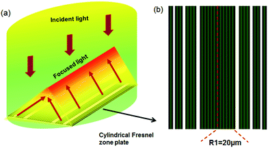 | ||
| Fig. 1 Plasmonic FZP lens model. (a) Schematic of graphene FZP lens operating in reflection mode. (b) Design of cylindrical selective enhanced graphene FZP lens. | ||
The graphene cylindrical lens only works in response to specific polarizations of light. For incident light polarized parallel to the NRs, the electrical response of charge carriers is similar to that of free electrons in a homogeneous graphene sheet; while for incident light polarized perpendicular to the NRs, an absorption peak originating from plasmonic oscillations is observed.29,36 In mid-infrared wavelength range, if light polarization is parallel to the highly doped graphene NRs, the interaction with light is insignificant due to Pauli blocking of the interband transitions and the weakness of the free-carrier intraband transitions at such high frequencies.40
Fig. 2 shows the properties of monolayer graphene NR array at a Fermi level of 0.4 eV. The width of each NR was set to 160 nm, while the gap between the NRs was varied from 20 to 1500 nm. When the gap is smaller than 500 nm, the resonance wavelengths will red shift due to the increased coupling between adjacent NRs. The increased peak values are the result of the increased area covered by the NRs and the enhanced scattering effect. However, the resonance peak for a gap of 20 nm is smaller than that for 40 nm, which may be due to stronger neighboring NR interaction. Fig. 2b shows that the resonance position is the same when the gap between the NRs is larger than their widths, in which the NR-to-NR hybridization can be neglected41 and the resonance wavelengths only depend on the width of graphene NRs.
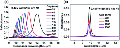 | ||
| Fig. 2 Vibration of the resonance wavelength with gaps varying from (a) 20 to 500 nm and (b) 500 to 1500 nm. The graphene NR width w is set to 160 nm with EF = 0.4 eV. | ||
The resonance wavelength λ of graphene NR array can be analyzed with a quasi-static equation:29,42
 | (2) |
Fig. 3a shows that the resonance wavelength of monolayer graphene NR array obtained from finite difference time-domain (FDTD) simulations, for different NR widths at constant Fermi level of 0.8 eV. This corresponds to the analytical method in eqn (2) with η = 3.12. The graphene to gap ratio was set to 1, and Fig. 3a shows that increasing graphene NR width red-shifts the resonance wavelength. In Fig. 3b, a blue-shift of resonance wavelength is observed in response to increasing Fermi levels, irrespective of the number of graphene layers (1 or 4). The full width at half maximum (FWHM) of the peaks becomes narrower, which shows a narrow-band excitation. This behavior enhances the sensitivity with increased number of layers or Fermi levels. ESI Fig. S2† demonstrates that the resonance wavelength shifts to shorter wavelengths with higher peak value when the number of graphene layers increases, which is due to the strong Coulomb interactions.36
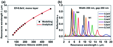 | ||
| Fig. 3 Excitation of resonance wavelength with varying (a) w at EF = 0.8 eV, and (b) Fermi levels at w = 250 nm. In both cases, the duty cycle of the NR array is 1/2. | ||
Simulation of wavelength-selective enhanced graphene lens
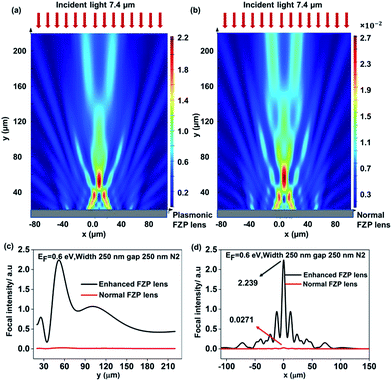
Based on the plasmonic responses of NRs, further simulations of the plasmonic FZP lenses were performed. Multilayered graphene lens was considered with turbostratic stacking. Fig. 4 shows the lensing effect of a two-layer graphene plasmonic FZP lens (NRs in dark zones) and a conventional graphene FZP lens (without NRs) in similar conditions. Unlike the conventional FZP lens, the plasmonic FZP lens was composed of NR arrays with a period of 500 nm and w = 250 nm. A resonance wavelength of 7.4 μm was observed for a plasmonic lens under 0.6 eV Fermi level.Light intensity distributions on the focal plane for the plasmonic FZP lens and conventional FZP lens are shown in Fig. 4a and b, respectively. Similar diffraction based focusing patterns are observed, but with different focal intensities. Fig. 4c and d shows the power flow distribution extracted along the focal planes (vertically at x = 0) and at the focal points (horizontally). Enhancement of focal intensity for plasmonic FZP lens was observed, which focused ∼83 times more light as compared to the conventional FZP lens. According to the properties of graphene NRs array, higher enhancement may be achieved if the gaps between the NR arrays are smaller (although with a red shifted resonance wavelengths).
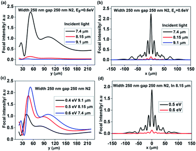
The wavelength selectivity at which the plasmonic resonance and focal intensity enhancement occurred was studied (Fig. 5). The focusing performance of plasmonic lens (same dimension as in Fig. 4) was compared at incident wavelengths of 7.4, 8.15, and 9.1 μm. These are the respective resonance wavelengths for the lens under Fermi levels of 0.6, 0.5, and 0.4 eV. Under a fixed Fermi level of 0.6 eV, with broadband incident light, the lensing effect is only enhanced at the resonance wavelength (7.4 μm). The focal point intensity for 7.4 μm incident light is 70 times higher than that for 9.1 μm wave. Thus, with broadband incident light, the graphene plasmonic FZP lens can work as a wavelength filter, which only focuses light at the resonant wavelength.
The resonance wavelength can be adjusted by changing the Fermi level, allowing the tunability of the resonance frequency. Fig. 5c compares the focal intensity (vertically along x = 0) at different Fermi levels with incident light of corresponding resonance wavelengths. The focal lengths for incident wavelengths of 7.40, 8.15 and 9.10 μm are 52.00, 46.25 and 41.25 μm respectively, which are in agreement with the theoretical values (54.05, 49.08, and 43.96 μm) calculated from FZP equation. This shows that plasmonic effect only contributes toward the focal intensity, without changing the diffraction properties of FZP lenses. Fig. 5c also shows that shorter incident wavelengths (black line) lead to higher focal intensity, which satisfies the properties of graphene NR arrays in Fig. 3. At higher Fermi levels, the resonance wavelengths are shorter and display higher peak intensities. Higher reflections from the NRs allow higher focal intensity for the lens. Fig. 5d illustrates that at single wavelength incident light, the enhanced lensing effect could be tuned by adjusting the Fermi levels. With incident light of 8.15 μm, the peak plasmonic resonance occurs at a Fermi level of 0.6 eV, providing a focal intensity that is 13 times higher than at a Fermi level of 0.5 eV. Therefore, the graphene plasmonic lens can be used as a switch, which can be turned on or off by changing the applied voltage.
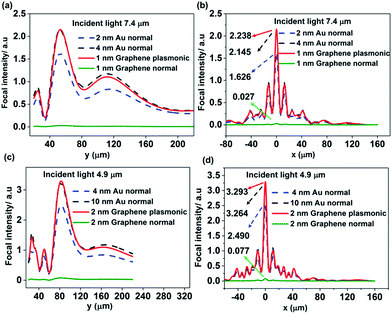
The lensing effects of graphene plasmonic FZP lenses are also compared with conventional metal FZP lenses (without NRs) (Fig. 6). All the lenses are of the same size, while the plasmonic lenses consist of NR array with a NR width of 250 nm and a gap of 250 nm. In this study, the focal intensities of two-layered (∼1 nm) and four-layered (∼2 nm) graphene plasmonic lenses were studied. The results are compared with gold (Au) thin film based FZP lenses, with almost double thickness of 2 and 4 nm, respectively. Thicker metal lenses are simulated to find the minimum thickness that can achieve a focal intensity comparable to graphene plasmonic lenses.
The results demonstrate that achieving comparable focal intensities, the graphene plasmonic lens requires a lower thickness as compared to the Au FZP lens. For a 7.4 μm incident light, a 4 nm thick Au FZP lens produces a focal intensity that is comparable to the intensity produced by a 1 nm thick graphene plasmonic lens (Fig. 6a and b). Additionally, the focal intensity of 4-layer (2 nm) graphene plasmonic FZP lens (Fermi level of 0.7 eV and incident light of 4.9 μm) is studied and it can generate focal intensity comparable to 10 nm thick normal Au FZP lens (Fig. 6c and d). A four-layer graphene plasmonic lens can achieve higher focal intensity than both of the conventional Au thin film based FZP lenses in similar condition. Therefore, this study shows that a graphene plasmonic lens can achieve comparable lensing effects to conventional Au FZP lenses, but with a thinner geometry and having an additional advantage of tunability.
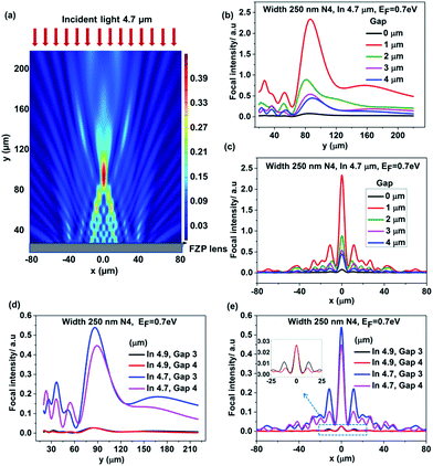
The effect of the gap between graphene NRs on the lensing is also studied. Fig. 7a shows the power flow distribution for 4.7 μm incident light, which is the resonance wavelength for graphene plasmonic lens with Fermi levels of 0.7 eV, NR widths of 250 nm and gaps of 4 μm. Fig. 7b and c show the vertical and horizontal cross-sectional intensity plots (at the focal plane) as the gaps changes from 0 to 4 μm. When the gap is 0, the lens is a conventional FZP lens without any enhanced effect, thus with the lowest focal intensity, which is only 1/30th of the highest value obtained for a gap of 1 μm. When the gaps increase from 1 to 2 μm, the focal intensity decreases dramatically due to the decreased density of graphene NRs. The focal intensities for gaps 3 and 4 μm are close to each other. The smallest grating period that could diffract light is half of the incident light, and the effect is most pronounced when the period is comparable to the incident light. The diffraction between NRs within one FZP ring will occur when the gap is larger than λ/2 − w = 2.1 μm, and has the strongest effect with gap λ − w = 4.45 μm. It is suspected that coupling between graphene NRs within one FZP ring will contribute to the total lensing effect. To further study this, we simulated plasmonic lenses with NR of gaps 3 and 4 μm, at 4.9 μm incident light (Fig. 7d and e).
Fig. 7d shows a high wavelength sensitivity of the tunable effect displayed by the graphene plasmonic lenses. A small change in the incident light, with Δλ/λ = 2/47, will lead to a dramatic change in the focal intensity, which is as high as ΔI/I ≈ 19/20. The effect can also be seen in Fig. 7e, in which the main lobes for gap 3 and 4 μm are the same while gap 3 μm has a higher second lobe (peak). If we use the ratio between the intensity of the main lobe and the second lobe to be a parameter demonstrating the lens efficiency, gap 4 μm results in higher efficiency, which may be due to the larger diffractive contribution of the NRs within FZP zones. This is also be confirmed when the incident light is 4.7 μm, the ratio between the highest peak I1 and the second high peak I2 is 2.45 and 4.37 for gap 3 and 4 μm, respectively. The diffraction efficiency variation with incident wavelengths was also studied (ESI Fig. S3†). When the gap is equal to the wavelength of incident light, the diffraction between the ribbons is so strong that the focal point and the power distribution pattern changes significantly.
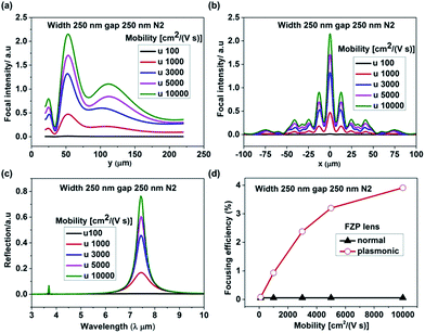
The effects of carrier mobility on graphene FZP lens performance were also studied. With different mobility of carriers, the resonance wavelength of graphene plasmons remains the same while the reflection intensity changes (Fig. 8a). This figure shows variation in focusing intensity for a two-layer graphene plasmonic lens (Fermi level = 0.6 eV, NR width = 250 nm and gap = 250 nm) with different carrier mobilities. The higher carrier mobility leads to higher focal intensity due to the stronger plasmonic effects in graphene NRs.
In Fig. 8d, the focusing efficiency of graphene plasmonic lenses and conventional FZP lenses are compared at different carrier mobilities. The lensing efficiency of normal graphene FZP lens is not affected by variation in carrier mobility. The efficiency remains constant at ∼0.055%, which is in agreement with the literature.43 However, the graphene plasmonic lens displays increased focusing efficiency at higher carrier mobilities.
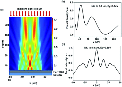
The plasmonic graphene FZP lens also demonstrates high performance on a silicon substrate (Fig. 9). The interaction between the graphene lens and the substrate will red shift resonance wavelength (ESI Fig. S4†). Fig. 9a shows the power flow distribution for a six-layer graphene lens on silicon substrate, with Fermi level = 0.8 eV and incident light 8.8 μm (resonance wavelength). The width and gap of the graphene NRs are 250 nm and 1 μm, respectively. Fig. 9b shows that the focal point is near 46 μm, which is close to the theoretical value of 45.45 μm. Fig. 9c demonstrates the intensity distribution across the horizontal cross-section at the focal plane. As compared with the previous results (graphene lenses in free space), the peak in Fig. 9c is broadband due to the background reflections from silicon (ESI Fig. S4†).
Conclusions
A wavelength-selective and tunable plasmonic graphene FZP lens is computationally studied using FDTD method. The results show that the focal intensity of the lens could be enhanced at the resonance wavelength, which could be tuned passively by changing the number of graphene layers, NR widths or actively by changing the Fermi levels and changed mobilities. In response to broadband incident light, the lens can work as a filter to focus specific wavelengths. When incident with single wavelength light, the lens will work as a switch, which can be turned on and off by changing Fermi levels.The plasmonic effect only contributes to the focal intensity, without changing other FZP lens properties such as focal length. The focal length of the graphene plasmonic lens is dictated by the incident wavelengths and the parameters of the FZP lens (zone dimensions). The gap between the graphene NRs plays a role in lens design. From the perspective of wavelength-selective enhancement, the gaps should not be too small as NRs will couple with each other and decrease the focused intensities. The gap should neither be too large as the intensity will decrease due to low material density and diffraction between the NRs within a FZP rings will affect the lensing behavior. At the same time, the interactions of diffractions within and between FZP rings, which can change the lensing effect significantly, may lead to new metamaterial devices. The plasmonic graphene FZP lens also demonstrates reasonable performance on silicon substrates, which is promising for device fabrication.
In the present work, metallic plasmonic nanoribbon-based FZP lenses are not modelled due to its complexity as well as their different resonant regimes. For example, for Au based plasmonic FZPs, nanostructures are required to be specifically designed to generate plasmons. Additionally, such metal-based plasmonic lenses will operate in the visible regime, thus it is hard to compare the performance with the graphene plasmonic lenses, which operate in the infrared/THz wavelength ranges.
Despite the simple structure of the graphene plasmonic FZP lens, the experiments are challenging to carry out due to both fabrication as well as characterization limitations. The plasmonic lens has high requirements for the fabrication techniques, because the defects and layers of graphene will play an important role on the resonant wavelength. The substrate also red shifts the resonant wavelength. A cylindrical graphene plasmonic FZP lens has been fabricated (ESI Fig. S5†). However, there were challenges faced in detecting its focal point and lensing effect. Firstly, according to the simulation, graphene plasmonic lens works in mid-infrared to THz regime. However, it was difficult to find the corresponding imaging system at such wavelengths and also the resolution of the conventional commercial infrared camera is low to detect such a micro scale lens. Secondly, compared with circular FZP lens, cylindrical FZP lens focuses light into a line instead of a point. Hence, detecting the lensing effect of cylindrical lenses is harder as they produce a weaker focusing intensity. With the development of fabrication and characterization techniques, the device can be detected in the future.
We have demonstrated a hybrid combination of plasmonics nanostructures and diffractive optics to produce a wavelength-selective and tunable graphene metamaterial lens, for potential application in infrared imaging, switching, and communications.
Experimental
Properties of graphene NRs
To study the enhanced FZP lens in 2D, the properties of graphene nanoring/nanoribbon arrays were studied by FDTD method, in which the lenses were illuminated perpendicularly by a plane wave. In the infrared regime, the contribution of interband for surface conductivity of graphene can be neglected and the conductivity can be approximated with a Drude expression:44
 | (3) |
![[thin space (1/6-em)]](https://www.rsc.org/images/entities/char_2009.gif) 000 cm2 V−1 s−1 is the measured dc mobility, e is the electron charge and νF = 1 × 10⁶ m s−1 is the Fermi velocity. Our previous study about graphene normal FZP lens demonstrated that when the carrier mobility changes from 1000 to 10
000 cm2 V−1 s−1 is the measured dc mobility, e is the electron charge and νF = 1 × 10⁶ m s−1 is the Fermi velocity. Our previous study about graphene normal FZP lens demonstrated that when the carrier mobility changes from 1000 to 10![[thin space (1/6-em)]](https://www.rsc.org/images/entities/char_2009.gif) 000 cm2 V−1 s−1, only the reflected intensity of the lens will be changed, but with almost the same focusing efficiency.45 For N-layer graphene, the conductivity is taken as σN(ω) = Nσ(ω).36,46 The graphene NR arrays were placed in x, z plane and light was incident normally from y direction. The anisotropic permittivity was obtained from the following equation:44
000 cm2 V−1 s−1, only the reflected intensity of the lens will be changed, but with almost the same focusing efficiency.45 For N-layer graphene, the conductivity is taken as σN(ω) = Nσ(ω).36,46 The graphene NR arrays were placed in x, z plane and light was incident normally from y direction. The anisotropic permittivity was obtained from the following equation:44
 | (4) |
| εyy = εr |
Notes
H. B conceived the idea. S. D did the modelling study. A. K. Y. edited the article. The manuscript was written through contributions of all authors. The authors declare no competing financial interests.Acknowledgements
H.B. thanks the Leverhulme Trust and Royal Society for the research funding. This study was partly funded by the European Union through the projects Graphene Flagship (No. 604391) and Core1 (No. 696656).References
- K. S. Novoselov, A. K. Geim, S. V. Morozov, D. Jiang, Y. Zhang, S. V. Dubonos, I. V. Grigorieva and A. A. Firsov, Science, 2004, 306, 666–669 CrossRef CAS PubMed.
- K. S. Novoselov, A. K. Geim, S. V. Morozov, D. Jiang, M. I. Katsnelson, I. V. Grigorieva, S. V. Dubonos and A. A. Firsov, Nature, 2005, 438, 197–200 CrossRef CAS PubMed.
- E. Hendry, P. J. Hale, J. Moger, A. K. Savchenko and S. A. Mikhailov, Phys. Rev. Lett., 2010, 105, 097401 CrossRef CAS PubMed.
- S. A. Mikhailov, Phys. Rev. B: Condens. Matter Mater. Phys., 2011, 84, 045432 CrossRef.
- A. E. Nikolaenko, N. Papasimakis, E. Atmatzakis, Z. Luo, Z. X. Shen, F. De Angelis, S. A. Boden, E. Di Fabrizio and N. I. Zheludev, Appl. Phys. Lett., 2012, 100, 181109 CrossRef.
- C.-F. Chen, C.-H. Park, B. W. Boudouris, J. Horng, B. Geng, C. Girit, A. Zettl, M. F. Crommie, R. A. Segalman, S. G. Louie and F. Wang, Nature, 2011, 471, 617–620 CrossRef CAS PubMed.
- M. Grzelczak, J. Perez-Juste, P. Mulvaney and L. M. Liz-Marzan, Chem. Soc. Rev., 2008, 37, 1783–1791 RSC.
- F. H. L. Koppens, D. E. Chang and F. J. García de Abajo, Nano Lett., 2011, 11, 3370–3377 CrossRef CAS PubMed.
- H. Yan, Z. Li, X. Li, W. Zhu, P. Avouris and F. Xia, Nano Lett., 2012, 12, 3766–3771 CrossRef CAS PubMed.
- Z. Fei, A. S. Rodin, G. O. Andreev, W. Bao, A. S. McLeod, M. Wagner, L. M. Zhang, Z. Zhao, M. Thiemens, G. Dominguez, M. M. Fogler, A. H. C. Neto, C. N. Lau, F. Keilmann and D. N. Basov, Nature, 2012, 487, 82–85 CAS.
- J. Chen, M. Badioli, P. Alonso-Gonzalez, S. Thongrattanasiri, F. Huth, J. Osmond, M. Spasenovic, A. Centeno, A. Pesquera, P. Godignon, A. Zurutuza Elorza, N. Camara, F. J. G. de Abajo, R. Hillenbrand and F. H. L. Koppens, Nature, 2012, 487, 77–81 CAS.
- A. Grigorenko, M. Polini and K. Novoselov, Nat. Photonics, 2012, 6, 749–758 CrossRef CAS.
- F. J. García de Abajo, ACS Photonics, 2014, 1, 135–152 CrossRef.
- M. Tonouchi, Nat. Photonics, 2007, 1, 97–105 CrossRef CAS.
- B. Ferguson and X.-C. Zhang, Nat. Mater., 2002, 1, 26–33 CrossRef CAS PubMed.
- R. Soref, Nat. Photonics, 2010, 4, 495–497 CrossRef CAS.
- H. Butt, Q. Dai, R. Rajesekharan, T. D. Wilkinson and G. A. Amaratunga, ACS Nano, 2011, 5, 9138–9143 CrossRef CAS PubMed.
- H. Butt, Q. Dai, P. Farah, T. Butler, T. D. Wilkinson, J. J. Baumberg and G. A. Amaratunga, Appl. Phys. Lett., 2010, 97, 163102 CrossRef.
- H. Butt, Q. Dai, N. N. Lal, T. D. Wilkinson, J. J. Baumberg and G. A. Amaratunga, Appl. Phys. Lett., 2012, 101, 083106 CrossRef.
- V. M. Shalaev, Nat. Photonics, 2007, 1, 41–48 CrossRef CAS.
- H. Butt, Q. Dai, T. D. Wilkinson and G. A. Amaratunga, Photonics and Nanostructures-Fundamentals and Applications, 2012, 10, 499–505 Search PubMed.
- B. Luk'yanchuk, N. I. Zheludev, S. A. Maier, N. J. Halas, P. Nordlander, H. Giessen and C. T. Chong, Nat. Mater., 2010, 9, 707–715 CrossRef PubMed.
- S. Kawata, Y. Inouye and P. Verma, Nat. Photonics, 2009, 3, 388–394 CrossRef CAS.
- W. Cai, U. K. Chettiar, A. V. Kildishev and V. M. Shalaev, Nat. Photonics, 2007, 1, 224–227 CrossRef CAS.
- S. Badhwar, J. Sibik, P. R. Kidambi, H. E. Beere, J. A. Zeitler, S. Hofmann and D. A. Ritchie, Appl. Phys. Lett., 2013, 103, 121110 CrossRef.
- R. Degl’Innocenti, D. S. Jessop, Y. D. Shah, J. Sibik, J. A. Zeitler, P. R. Kidambi, S. Hofmann, H. E. Beere and D. A. Ritchie, ACS Nano, 2014, 8, 2548–2554 CrossRef PubMed.
- R. Degl’Innocenti, D. S. Jessop, Y. D. Shah, J. Sibik, J. A. Zeitler, P. R. Kidambi, S. Hofmann, H. E. Beere and D. A. Ritchie, Opt. Eng., 2014, 53, 057108 CrossRef.
- G. Yao, F. Ling, J. Yue, Q. Luo and J. Yao, J. Lightwave Technol., 2016, 34, 3937–3942 Search PubMed.
- L. Ju, B. Geng, J. Horng, C. Girit, M. Martin, Z. Hao, H. A. Bechtel, X. Liang, A. Zettl, Y. R. Shen and F. Wang, Nat. Nanotechnol., 2011, 6, 630–634 CrossRef CAS PubMed.
- A. Andryieuski, A. V. Lavrinenko and D. N. Chigrin, Phys. Rev. B: Condens. Matter Mater. Phys., 2012, 86, 121108 CrossRef.
- G. Wang, X. Liu, H. Lu and C. Zeng, Sci. Rep., 2014, 4, 4073 Search PubMed.
- M. Karabiyik, C. Al-Amin, S. Das, N. Pala and W. B. Choi, Subwavelength, multimode, tunable plasmonic terahertz lenses and detectors, SPIE Defense, Security, and Sensing, 2012, 83630L-83630L-8.
- M. Karabiyik, C. Al-Amin and N. Pala, IEEE Trans. Terahertz Sci. Technol., 2013, 3, 550–557 CrossRef CAS.
- H. Butt, R. Rajesekharan, Q. Dai, S. Sarfraz, R. V. Kumar, G. A. Amaratunga and T. D. Wilkinson, Appl. Phys. Lett., 2012, 101, 243116 CrossRef.
- R. Ranjith, H. Butt, T. Wilkinson and G. Amaratunga, Adv. Mater., 2012, 24, OP170–OP173 Search PubMed.
- H. Yan, X. Li, B. Chandra, G. Tulevski, Y. Wu, M. Freitag, W. Zhu, P. Avouris and F. Xia, Nat. Nanotechnol., 2012, 7, 330–334 CrossRef CAS PubMed.
- T. Low and P. Avouris, ACS Nano, 2014, 8, 1086–1101 CrossRef CAS PubMed.
- Y.-H. Fan, H. Ren and S.-T. Wu, Opt. Express, 2003, 11, 3080–3086 CrossRef PubMed.
- S. Deng, P. Penchev, J. Liu, Y. Wang, K. Jiang, S. Dimov, Z. Zhang, Y. Liu, J. Leng and H. Butt, Nanoscale, 2015, 7, 12405–12410 RSC.
- H. Yan, F. Xia, W. Zhu, M. Freitag, C. Dimitrakopoulos, A. A. Bol, G. Tulevski and P. Avouris, ACS Nano, 2011, 5, 9854–9860 CrossRef CAS PubMed.
- A. Y. Nikitin, F. Guinea, F. J. Garcia-Vidal and L. Martin-Moreno, Phys. Rev. B: Condens. Matter Mater. Phys., 2012, 85, 081405 CrossRef.
- J. Liu, A. G. Rinzler, H. Dai, J. H. Hafner, R. K. Bradley, P. J. Boul, A. Lu, T. Iverson, K. Shelimov, C. B. Huffman, F. Rodriguez-Macias, Y.-S. Shon, T. R. Lee, D. T. Colbert and R. E. Smalley, Science, 1998, 280, 1253–1256 CrossRef CAS PubMed.
- X.-T. Kong, H. Butt, A. K. Yetisen, C. Kangwanwatana, Y. Montelongo, S. Deng, F. da Cruz Vasconcellos, M. M. Qasim, T. D. Wilkinson and Q. Dai, Appl. Phys. Lett., 2014, 105, 053108 CrossRef.
- S. Deng, A. K. Yetisen, K. Jiang and H. Butt, RSC Adv., 2014, 4, 30050–30058 RSC.
- Q. Zhang, E. H. Hároz, Z. Jin, L. Ren, X. Wang, R. S. Arvidson, A. Lüttge and J. Kono, Nano Lett., 2013, 13, 5991–5996 CrossRef CAS PubMed.
- W. Xiong, Y. S. Zhou, W. J. Hou, L. J. Jiang, Y. Gao, L. S. Fan, L. Jiang, J. F. Silvain and Y. F. Lu, Sci. Rep., 2014, 4, 4892 CAS.
Footnote |
| † Electronic supplementary information (ESI) available: E-field distribution on xz plane of a monolayer graphene ribbon array and ring array at the resonance wavelength; reflection of graphene ribbons array with different layers; power flow distribution from four/five-layer graphene FZP lens. See DOI: 10.1039/c6ra27942b |
| This journal is © The Royal Society of Chemistry 2017 |

