DOI:
10.1039/C6RA27908B
(Paper)
RSC Adv., 2017,
7, 6671-6678
Synthesis of Y2O3:Bi3+,Yb3+ nanosheets from layered yttrium hydroxide precursor and their photoluminescence properties†
Received
8th December 2016
, Accepted 12th January 2017
First published on 20th January 2017
Abstract
Y2O3:Bi3+,Yb3+ fluorescent nanosheets were prepared through calcining solvothermally synthesized layered yttrium hydroxide precursors at 600–1200 °C. X-ray diffraction (XRD) and transmission electron microscope (TEM) images confirmed that the nanosheets were polycrystalline with uniform crystallographic orientation. TEM images also confirmed that the nanosheet structure was maintained after calcination at temperatures up to 1000 °C. Atomic force microscope (AFM) images revealed that the Y2O3:Bi3+,Yb3+ nanosheets had thicknesses of 10–30 nm. The photoluminescence excitation (PLE) spectrum featured a broad band at 332 nm corresponding to the 1S0 → 3P1 transition of Bi3+. The emission spectrum featured a peak at 976 nm corresponding to the 2F5/2 → 2F7/2 transition of Yb3+. The photoluminescence (PL) intensity and PL lifetime increased with increasing calcination temperature, because of the improved crystallinity of Y2O3:Bi3+,Yb3+. The photostability of the nanosheets was evaluated by measuring the change in PL intensity under continuous irradiation by near-ultraviolet light for 2 h. The PL intensity of the nanosheets increased therein, possibly because of photooxidation by ambient oxygen of bismuth or ytterbium ions that were reduced during the solvothermal reaction.
1 Introduction
Photovoltaic generation of electricity is a green and renewable energy source that has attracted attention as a replacement for fossil fuels. The most commonly used solar cells are of the crystalline silicon type. However, their energy conversion efficiency has a theoretical limit of around 30%, known as the Shockley–Queisser limit.1,2 In practice, the conversion efficiency is further lowered by effects such as reflection, lattice thermalization, and absorption by coatings, which lead to final conversion efficiencies of 25.6% at the highest.3 Another major cause of energy loss is spectral mismatch between the solar spectrum and the energy band gap of the semiconductor in photovoltaic devices. When a photon with an energy higher than the band gap of crystalline silicon (Eg = 1.12 eV) is absorbed, the excess energy is rapidly lost by thermalization. Photons with lower energy than the band gap cannot be absorbed at all, resulting in transmission loss. To overcome spectral mismatch, the use of spectral converters is considered a promising approach. Spectral conversion involves two separate luminescent processes, up-conversion and down-conversion.4 In up-conversion, two or more low-energy photons are converted to one higher-energy photon.5–8 Up-conversion is useful for minimizing transmission losses. Down-conversion is the opposite process to up-conversion, in which one high-energy photon is converted into two photons of lower energy.9–12 Down-conversion acts to reduce thermalization losses. Since down-conversion ideally produces more than one low-energy photon per one high-energy incident photon (known as quantum cutting), in principle it has a quantum efficiency of more than 100% and is thus suitable for increasing the conversion efficiency. By applying down-conversion to crystalline silicon solar cells, it is estimated that the theoretical conversion efficiency can be increased by up to 38.6%.13 Among the suitable materials for spectral converters are lanthanide-doped phosphors. Lanthanides are found mostly in the trivalent form, with an electron configuration of 4fn5s25p6, where n varies from 0 to 13. The abundant energy levels arising from these 4f orbitals enable lanthanides to exhibit UV absorption with subsequent infrared emission.14 Because the 4f shell is well shielded by the 5s and 5p shells, the energy levels are insensitive to the host environment. Hence, the luminescent wavelengths show little variation when changing the host material.
As a common host for luminescent materials, Y2O3 has been studied widely for its high refractive index, thermal stability, and chemical durability. It is an excellent host matrix for rare earth activators and possesses various PL properties when doped with rare earth metals. Much research has been conducted to produce specific morphologies of Y2O3, such as nanorods,15 nanotubes,16 microprisms,17 and microspheres.18 As a spectral-converter layer for solar cells, the nanosheet morphology is thought to be especially suitable because nanosheets can be easily fabricated into highly oriented thin films through layer-by-layer and electrophoretic deposition techniques.19–22 Various synthetic methods have been investigated for Y2O3, including microemulsion,23 combustion,24 and solid-state reaction.25 As an alternative to these, hydrothermal synthesis is a mild and facile method to prepare well-crystallized materials with controlled morphology.26–28 However, Y2O3 is not stable under hydrothermal conditions at temperatures lower than 550 °C.29 Therefore, Y2O3 products are generally synthesized from hydrothermally prepared precursors formed at low temperature rather than through direct formation of the oxide itself.30 Using familiar methods, Y2O3 has been synthesized by calcining precursors such as Y4O(OH)9(NO3) or Y(OH)3.31 To obtain a nanosheet structure, layered yttrium hydroxide (LYH) is a potential candidate precursor. LYH, which is composed of inorganic layers stacked along the [00l] direction, develops a nanosheet structure through crystallization along the (00l) plane under hydrothermal conditions.32 Not only can it be transformed to Y2O3 by calcination, but also, because the (001) plane of LYH and the (111) plane of Y2O3 have a similar rare earth atom arrangement, a [111]-oriented Y2O3 is thought to be obtained through quasi-topotactic transformation.32 Moreover, the sheet-like morphology of LYH can be maintained after calcination.33,34 Similarly to Y2O3, LYH can be substitutionally doped with trivalent rare earth metal ions into the yttrium sites, endowing it with PL properties.
For down-conversion in crystalline silicon solar modules, the emission from Yb3+ between 900 and 1100 nm is favorable since it is well matched with the maximum spectral response of crystalline silicon solar cells. In the past, many combinations of ions with Yb3+ have been studied for quantum cutting, such as Tb3+–Yb3+,35 Tm3+–Yb3+,36 and Pr3+–Yb3+.37 Quantum cutting occurs through the sensitizer ions transferring energy to the activator ion, Yb3+, by converting a photon with a shorter wavelength into two near-infrared (NIR) photons. However, these sensitizer ions show narrow excitation peaks and have low absorption efficiency because the 4f–4f transitions are forbidden.9 To harvest solar energy more effectively, we predicted that Bi3+ should be an efficient sensitizer since it can be directly excited through the 1S0–3P1 transition at a broad wavelength range of 300–400 nm.9 Herein, we chose Bi3+–Yb3+ as a sensitizer–activator couple and fabricated Y2O3:Bi3+,Yb3+ as a down-converter. To obtain Y2O3:Bi3+,Yb3+ in nanosheet form, LYH:Bi3+,Yb3+ precursor nanosheets were synthesized based on the solvothermal method reported by Xiang et al.,38 and then calcined at various temperatures. The overall influence of the calcination temperature on the morphology and PL properties of the obtained Y2O3:Bi3+,Yb3+ nanosheets was investigated and reported.
2 Experimental section
2.1 Materials
YCl3·6H2O (99.99%), BiCl3 (99.5%), Bi2O3 (98.0%), and methanol (99.8%) were purchased from Kanto Chemical. YbCl3·6H2O (99.9%), Y2O3 (99.99%), and Yb2O3 (99.9%) were purchased from Wako Pure Chemical Industries. Polyethyleneimine (PEI, Mw = 25![[thin space (1/6-em)]](https://www.rsc.org/images/entities/char_2009.gif) 000, 99%) was purchased from Sigma-Aldrich. All reagents were used without further purification.
000, 99%) was purchased from Sigma-Aldrich. All reagents were used without further purification.
2.2 Preparation of precursors and calcined samples
0.470 mmol of YCl3·6H2O, 0.005 mmol of BiCl3, and 0.025 mmol of YbCl3·6H2O were added to 16 mL of methanol. Then, the mixture was added into 5 mL of 2 wt% PEI aqueous solution. The resulting suspension was placed in a Teflon vessel with a volume of 50 mL and heated in a stainless-steel autoclave (Berghof, DAB-2) at 200 °C for 2.5 h. After cooling the autoclave to room temperature with placing it in water, the precipitate was isolated by washing with ethanol, followed by 5 min of centrifugation at ∼11000 × g (10000 rpm using a rotor with a diameter of 10 cm). This cycle of washing and centrifugation was performed twice. The precipitate was then dried at 60 °C for 5 h to obtain the precursors. The precursors were heated at temperatures ranging from 600 °C to 1200 °C with a heating rate of 10 °C min−1 in an air flow of 300 mL min−1, and kept at the designated temperatures for 2 h to obtain the calcined samples.
2.3 Characterization
Thermal analysis was performed on a thermogravimetry and differential thermal analysis (TG-DTA) instrument (Thermo Plus TG8120, Rigaku) in an air flow of 300 mL min−1. XRD patterns were measured on an X-ray diffractometer (Rint-2200, Rigaku) with a Cu Kα radiation source and monochromator. Elemental compositions were determined by an X-ray fluorescence (XRF) analyzer (ZSX mini II, Rigaku). The calibration curve for the Bi concentration was obtained from the mixtures of Y2O3 and Bi2O3 at different ratios. The calibration curve for the Yb concentration was obtained from the mixtures of Y2O3 and Yb2O3 at different ratios. Fourier transform infrared (FT-IR) absorption spectra of pressed KBr disks containing the precursor and calcined samples were measured on an FT-IR spectrometer (FT/IR-4200, JASCO). Particle images were captured with a TEM (TecnaiG2, FEI). The samples for TEM were prepared by drying a drop of a methanol dispersion of each sample on a carbon-reinforced collodion film of a copper grid. Particles were also observed using an AFM (SPM-9700, Shimadzu) in dynamic mode. The samples for AFM were prepared by drying a drop of a methanol dispersion of each sample on a negative-type silicon wafer. PL and PLE spectra were recorded on a fluorescence spectrometer (FP-6600, JASCO) equipped with a near-infrared photomultiplier tube (R5509-43, Hamamatsu Photonics). Changes in PL intensity during continuous near-UV excitation were measured with the same apparatus. PL decay curves were recorded on a fluorescence lifetime spectrometer (Quantaurus-Tau C11367, Hamamatsu Photonics) using a Xe flash lamp with a band path filter of 365 nm.
3 Results and discussion
3.1 Structural properties of precursor and calcined samples
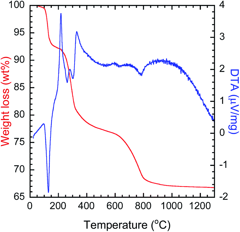
To determine the calcination temperature for the precursor, thermal analysis was performed (Fig. 1). The decomposition of LYH can be divided into three steps. The first step starts around 100 °C and involves the endothermic evaporation of interlayer water, with a total weight loss of 8.0 wt%. The second step occurs around 230 °C and is attributed to the endothermic reaction of Y2(OH)5Cl → Y2O2(OH)Cl, with a weight loss of 14.5 wt%. The third step occurs around 630 °C and is caused by the endothermic removal of chloride ions, Y2O2(OH)Cl → Y2O3, with a weight loss of 10.6 wt%.39 The decomposition of PEI can be assigned to the second step as the decomposition starts at 200 °C. Here, the third step, decomposition of the precursor, started at ∼600 °C. Therefore, to investigate the effect of calcination, a range of calcination temperatures were chosen between 600 °C and 1200 °C.
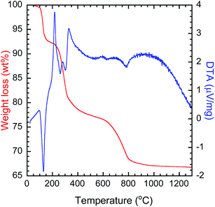 |
| | Fig. 1 TG-DTA thermogram of the solvothermally synthesized precursor. | |
Fig. 2(A) shows the XRD patterns of the as-obtained precursor and the calcined samples. The peaks for the precursor can be well indexed to the reported Y8(OH)20Cl4·nH2O, specifically, Y2(OH)5Cl·mH2O, belonging to the group of known LYH structures.31 Calcination of this precursor at temperatures of 700 °C and above resulted in the formation of phase-pure cubic Y2O3. After calcination at the lowest temperature, 600 °C, the XRD peak indexed to LYH remained at ∼10°. The (222) diffraction peak of Y2O3 was measured with high precision for the calcined samples (see Fig. S1 in the ESI†). With increasing calcination temperature, the observed (222) XRD peak became sharper and showed a continual shift toward higher diffraction angles, as shown in Table 1. The decrease in the interplanar spacing of (222) indicates that the lattice parameters were relaxed by calcination at higher temperatures. Fig. 2(B) shows the crystallite sizes of Y2O3 obtained at each calcination temperature. The crystallite size, as determined by the Scherrer equation from the width of the (222) peak, increased from 15 nm to 74 nm when increasing the calcination temperature from 600 °C to 1200 °C, indicating improved crystallinity at higher calcination temperatures. The metallic compositions of the calcined samples, as measured by XRF, are shown in Table 1. The presence of dopant ions of Bi and Yb was confirmed at all of the calcination temperatures. The measured Bi and Yb contents of Y2O3:Bi3+,Yb3+ were larger than their nominal contents.
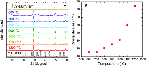 |
| | Fig. 2 (A) XRD profiles of LYH:Bi3+,Yb3+ precursor and of Y2O3:Bi3+,Yb3+ prepared at each calcination temperature. ICDD data of cubic Y2O3 (no. 089-5591) are also shown. (B) Change in crystallite size (determined from the width of (222) XRD peak of calcined samples) with calcination temperature. | |
Table 1 Peak position and interplanar spacing of (220) facet for LYH:Bi3+,Yb3+ (d220) and (222) facet for Y2O3:Bi3+,Yb3+ (d222) measured by XRD, and metallic composition of calcined samples measured by XRF
| Sample |
2θ (°) |
Interplanar spacing (nm) |
Y (at%) |
Bi (at%) |
Yb (at%) |
| Nominal ratio |
— |
— |
94.0 |
1.0 |
5.0 |
| LYH:Bi3+,Yb3+ precursor |
28.67 |
3.112 |
90.1 |
2.5 |
7.5 |
| Calcinated at 600 °C |
29.16 |
3.060 |
91.4 |
1.6 |
7.0 |
| Calcinated at 700 °C |
29.14 |
3.062 |
90.2 |
2.3 |
7.5 |
| Calcinated at 800 °C |
29.19 |
3.057 |
91.0 |
2.3 |
6.7 |
| Calcinated at 900 °C |
29.19 |
3.057 |
91.0 |
2.3 |
6.7 |
| Calcinated at 1000 °C |
29.20 |
3.056 |
90.5 |
2.3 |
7.3 |
| Calcinated at 1100 °C |
29.20 |
3.056 |
91.5 |
2.0 |
6.5 |
| Calcinated at 1200 °C |
29.22 |
3.054 |
91.0 |
1.7 |
7.3 |
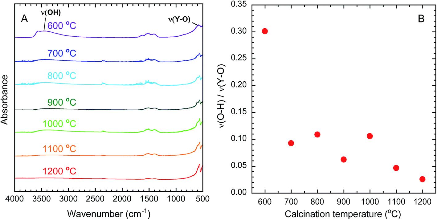
OH groups are known to quench near-infrared emission from Yb3+ because the energy of the emission matches that of the third harmonic vibrational mode of OH.40 The removal of OH groups by calcination can therefore be evaluated by FT-IR analysis. Fig. 3(A) presents the FT-IR spectra of the calcined samples. The broad absorption band around 3450 cm−1 is assigned to the stretching vibrations of O–H (ν(O–H)).41 The narrow band around 570 cm−1 is assigned to the stretching vibration of Y–O (ν(Y–O)).41 On this basis, the amount of O–H in each sample was evaluated by dividing the absorbance of (ν(O–H)) by the absorbance of (ν(Y–O)). As shown in Fig. 3(B), the values of ν(O–H)/ν(Y–O) decreased as the calcination temperature increased, indicating the effective removal of O–H groups at higher temperatures.
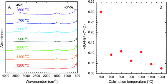 |
| | Fig. 3 (A) FT-IR spectra of Y2O3:Bi3+,Yb3+ prepared at each calcination temperature. (B) Change in the absorbance ratio of ν(O–H) to ν(Y–O) in calcined samples as a function of calcination temperature. | |
3.2 Morphology of precursor and calcined samples
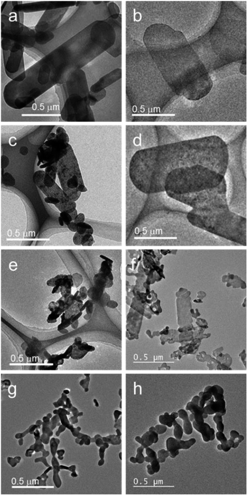
Fig. 4(a) shows a TEM image of the LYH:Bi3+,Yb3+ precursor, revealing that the precursor possessed a sheet-like structure. The average lateral sizes of 100 nanosheets were calculated (see Fig. S2 in the ESI†). For the LYH:Bi3+,Yb3+ precursor, the nanosheets were around 250 nm in length and 140 nm in width. The crystallite size, calculated from the precise width of the (220) diffraction peak of LYH (see Fig. S3 in the ESI†), was 97 nm, which was smaller than the nanosheet size determined from the TEM image. Each nanosheet was therefore composed of multiple crystallites. Fig. 5(a) and (b) show a high-resolution TEM image and the corresponding selected-area electron diffraction (SAED) pattern of the LYH precursor. The SAED pattern is similar to that previously reported by Yapryntsev et al.42 Fig. 5(c) and (d) show the high-resolution TEM image with a larger magnification and the corresponding fast Fourier transform (FFT) pattern, respectively, indicating that the LYH precursor was well-crystallized. The observed lattice fringe spacing, corresponding to the (400) plane of LYH, was 0.32 nm. The well-resolved spots of the SAED and FFT patterns indicate that this nanosheet, although composed of multiple crystallites, had a single-crystal nature, in which the crystallites had a uniform crystallographic orientation.
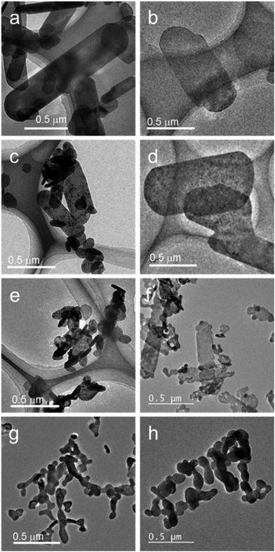 |
| | Fig. 4 TEM images of (a) LYH:Bi3+,Yb3+ precursor and Y2O3:Bi3+,Yb3+ nanosheets synthesized at calcination temperature of (b) 600 °C, (c) 700 °C, (d) 800 °C, (e) 900 °C, (f) 1000 °C, (g) 1100 °C, and (h) 1200 °C. | |
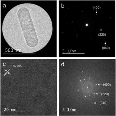 |
| | Fig. 5 High-resolution TEM image of the LYH:Bi3+,Yb3+ precursor nanosheet (a) and the corresponding SAED pattern (b). High-resolution TEM image with a larger magnification (c) and the corresponding FFT pattern (d). | |
As shown in Fig. 4, when the precursor was calcined in the temperature range of 600–1000 °C, the obtained Y2O3 inherited the sheet structure of the precursor. For the samples calcined at higher temperatures, i.e., 1100 °C and 1200 °C, the sheets started to sinter and transform into round particles. Therefore, to obtain Y2O3:Bi3+,Yb3+ in nanosheet form, the calcination must be carried out at a temperature between 700 °C and 1000 °C. The length and width of the precursor nanosheets were around 300 nm and 100 nm, respectively (see Fig. S2 in the ESI†). The size of the nanosheets did not change significantly even after calcination. Fig. 6(a) and (b) show a TEM image and the corresponding SAED pattern of the sample calcined at 1000 °C. Fig. 6(c) and (d) show a high-resolution TEM image and the corresponding FFT pattern, respectively. The observed lattice fringe spacing, corresponding to the (211) plane of Y2O3, was 0.46 nm. The well-resolved spots in the SAED and FFT patterns indicate that, like the precursor, the Y2O3:Bi3+,Yb3+ nanosheets also had a single-crystal nature.
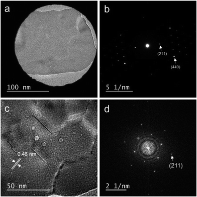 |
| | Fig. 6 High-resolution TEM image of the Y2O3:Bi3+,Yb3+ nanosheet calcined at 1000 °C (a) and the corresponding SAED pattern (b). High-resolution TEM image with a larger magnification (c) and the corresponding FFT pattern (d). | |
From the AFM images of the Y2O3:Bi3+,Yb3+ nanosheets calcined at 700 °C and 1000 °C (see Fig. S4 and S5 in the ESI†), it can be seen that the synthesized Y2O3:Bi3+,Yb3+ had a nanosheet structure, with a thickness estimated at ∼15 nm.
3.3 Influence of calcination temperature on PL properties of Y2O3:Bi3+,Yb3+ nanosheets
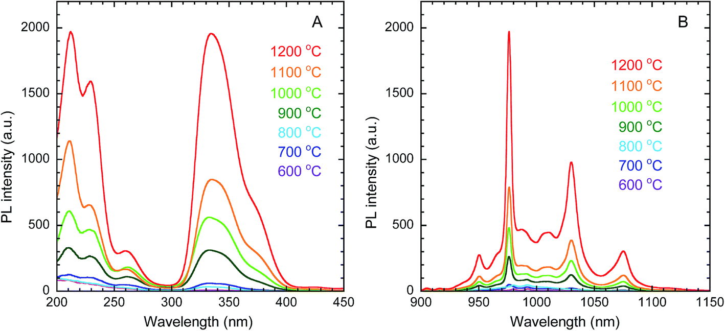
The PLE and PL spectra of the obtained Y2O3 nanosheets are shown in Fig. 7(A) and (B), respectively. In the PLE spectra monitored at 976 nm emission, corresponding to the 2F5/2 → 2F7/2 transition of Yb3+, a broad band with a peak at 332 nm was observed. This band is attributed to the 1S0 → 3P1 transition of Bi3+. The peak at 211 nm is attributed to host-lattice absorption by Y2O3.43 The peak at 228 nm is attributed to the O2− → Yb3+ charge transfer transition of the dopant Yb3+ ions in Y2O3.44 In the PL spectra monitored at 332 nm excitation, several peaks assigned to the 2F5/2 → 2F7/2 transition of Yb3+ were observed in the wavelength region of 930–1100 nm, arising from Stark splitting in the 2F5/2 and 2F7/2 levels of Yb3+. The strongest peak was observed at 976 nm. With increasing calcination temperature, the PL intensity of Yb3+ increased. This can be mainly attributed to the improvement in crystallinity, rather than the removal of O–H groups, since Fig. 8 shows that the PL intensity was more strongly correlated with the crystallite size than with the ν(O–H) absorbance.
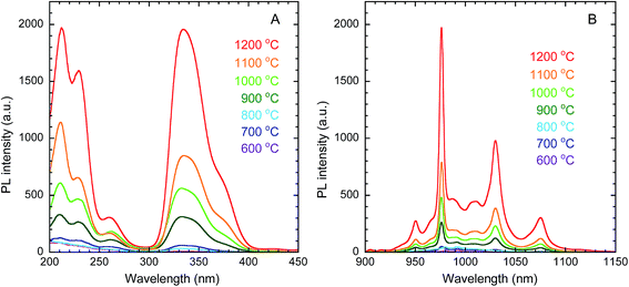 |
| | Fig. 7 PLE (A) and PL (B) spectra of Y2O3:Bi3+,Yb3+ nanosheets synthesized at each calcination temperature. λem = 976 nm, λex = 332 nm. | |
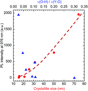 |
| | Fig. 8 PL intensity of Y2O3:Bi3+,Yb3+ nanosheets as a function of crystallite size and absorbance ratio of ν(O–H) to ν(Y–O). Red circles: crystallite size; blue triangles: ν(O–H)/ν(Y–O). | |
Fig. 9(A) shows the PL decay curves of the Y2O3:Bi3+,Yb3+ nanosheets. The curves can be fitted to a triple exponential by the following equation:
| | |
I = A1exp(−t/τ1) + A2exp(−t/τ2) + A3exp(−t/τ3)
| (1) |
where
I is the PL intensity at time
t, and
τx and
Ax (
x = 1, 2, and 3) are the PL lifetimes and constants, respectively. The fitted values are shown in
Table 2. From the three components of the PL lifetime, three relaxation routes are proposed for Yb
3+ ions depending on the site they occupy: (i) Yb
3+ ions distributed on the surface of the nanosheets, in sites that do not have inversion symmetry, which are strongly affected by the surface OH groups; (ii) Yb
3+ ions distributed among internal C
2 sites of the nanosheets, which is one of the two sites of Y
3+ in Y
2O
3 without inversion symmetry;
45 and (iii) Yb
3+ ions distributed among internal S
6 sites of the nanosheets, which is the other site of Y
3+ in Y
2O
3 that does have inversion symmetry. The PL lifetimes of the emissions, which each correspond to a forbidden f–f transition of Yb
3+, should increase in the order (i) → (ii) → (iii), corresponding to the observed
τ1,
τ2, and
τ3, respectively.
Fig. 9(B) shows the mean PL lifetime, calculated by
eqn (2):
| | |
τ = (A1τ12 + A2τ22 + A3τ32)/(A1τ1 + A2τ2 + A3τ3)
| (2) |
where
τ is the mean PL lifetime. The PL lifetime was found to increase with increasing calcination temperature. This trend was caused by the improvement in crystallinity, as that improvement is accompanied by the elimination of quenching defects, which contain trap levels causing non-radiative relaxation.
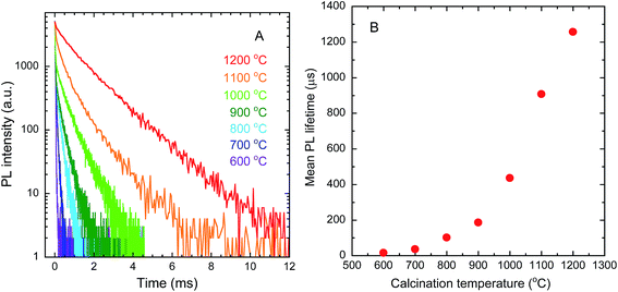 |
| | Fig. 9 PL decay curves (A) and mean PL lifetimes (B) of Y2O3:Bi3+,Yb3+ nanosheets synthesized at each calcination temperature. λex = 365 nm, λem = 976 nm. | |
Table 2 Calculated values of τx and Ax (x = 1, 2, and 3) from PL decay curves
| Calcination temperature (°C) |
τ1 (μs) |
τ2 (μs) |
τ3 (μs) |
A1 |
A2 |
A3 |
| 600 |
3.3 |
19.0 |
154.0 |
6027.2 |
4012.6 |
36.7 |
| 700 |
3.4 |
22.3 |
74.4 |
6364.6 |
3112.7 |
615.0 |
| 800 |
3.3 |
24.3 |
173.5 |
6233.4 |
3283.5 |
650.4 |
| 900 |
3.6 |
24.5 |
287.3 |
6496.1 |
3083.1 |
565.0 |
| 1000 |
14.4 |
182.2 |
575.0 |
5250.5 |
581.5 |
731.7 |
| 1100 |
17.2 |
296.1 |
941.9 |
6934.2 |
2084.3 |
1016.5 |
| 1200 |
14.8 |
514.3 |
1484.3 |
5674.3 |
1447.6 |
2942.2 |
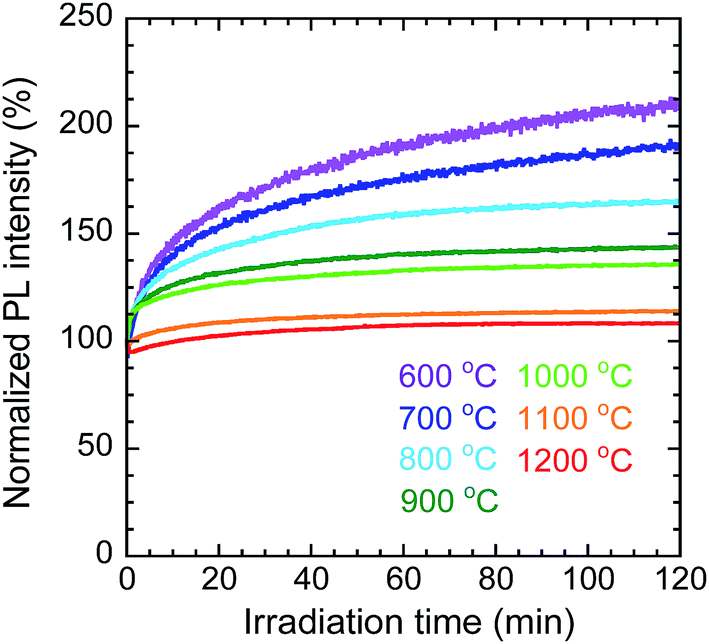
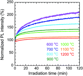
To evaluate the photostability of the nanosheets calcined at each temperature, the change in the PL intensity at 976 nm, corresponding to the 2F5/2 → 2F7/2 transition of Yb3+, was measured under continuous irradiation at 332 nm for 2 h. Fig. 10 shows the changes in PL intensity under continuous irradiation, normalized by the initial values (the raw data are shown in Fig. S6 in the ESI†). The PL intensity of the nanosheets calcined at 800 °C increased to 165% of its initial value; however, at higher calcination temperatures, the normalized intensity increased by successively smaller amounts (e.g., for the sample calcined at 1200 °C the final intensity was 108%). It is possible that some of the Bi3+ or Yb3+ cations were reduced by PEI or methanol during the solvothermal synthesis of the LYH precursors. In that case, for each sample, the increase in PL intensity over time would have resulted from the photooxidation of these reduced bismuth or ytterbium ions by oxygen in air during near-UV irradiation. The samples calcined at higher temperatures showed higher photostability because the reduced bismuth or ytterbium ions were more oxidized during calcination in flowing air.
 |
| | Fig. 10 Change in normalized PL intensity with irradiation time for Y2O3:Bi3+,Yb3+ nanosheets synthesized at each calcination temperature. λex = 332 nm, λem = 976 nm. | |
4 Conclusions
Y2O3:Bi3+,Yb3+ nanosheets were prepared by calcining solvothermally synthesized LYH precursor nanosheets. The crystallite sizes calculated from the XRD peaks were smaller than the lateral sheet sizes (hundreds of nanometers) measured by TEM, indicating that each nanosheet was composed of multiple crystallites. Nonetheless, the well-resolved spot patterns in the SAED and FFT images confirmed that the crystallites in the nanosheets had a uniform crystallographic orientation. The LYH was completely transformed into Y2O3 at calcination temperatures of 700 °C and above. TEM observation confirmed that the nanosheet structures remained after calcination at temperatures up to 1000 °C. AFM images indicated that the Y2O3:Bi3+,Yb3+ nanosheets had a thickness of ∼15 nm. The PL and PLE spectra of the Y2O3:Bi3+,Yb3+ nanosheets showed near-infrared emission from Yb3+ at 976 nm under near-UV excitation at 332 nm. The PL intensity and PL lifetime increased with increasing calcination temperature, predominantly because of an improvement in the crystallinity. The photostability of the Y2O3:Bi3+,Yb3+ nanosheets was evaluated by measuring the time-evolution of the PL intensity during continuous excitation. The PL intensity of all of the samples increased with irradiation time, possibly because bismuth or ytterbium ions that had been reduced during the solvothermal reaction were photooxidized by oxygen in air during near-UV excitation.
Acknowledgements
This work was supported by the Futaba Electronics Memorial Foundation and the Iketani Science and Technology Foundation.
References
- W. Shockley and H. J. Queisser, J. Appl. Phys., 1961, 32, 510–519 CrossRef CAS.
- C. A. Nelson, N. R. Monahan and X. Y. Zhu, Energy Environ. Sci., 2013, 6, 3508–3519 CAS.
- M. A. Green, K. Emery, Y. Hishikawa, W. Warta and E. D. Dunlop, Prog. Photovoltaics, 2016, 24, 3–11 Search PubMed.
- B. M. van der Ende, L. Aarts and A. Meijerink, Phys. Chem. Chem. Phys., 2009, 11, 11081–11095 RSC.
- J. de Wild, J. K. Rath, A. Meijerink, W. G. J. H. M. van Sark and R. E. I. Schropp, Sol. Energy Mater. Sol. Cells, 2010, 94, 2395–2398 CrossRef CAS.
- J. Silver, M. I. Martinez-Rubio, T. G. Ireland and G. R. Fern, J. Phys. Chem. B, 2001, 105, 948–953 CrossRef CAS.
- A. Shalav, B. S. Richards and T. Trupke, Appl. Phys. Lett., 2005, 86, 013505 CrossRef.
- C. Joshi, A. Dwivedi and S. B. Rai, Spectrochim. Acta, Part A, 2014, 129, 451–456 CrossRef CAS PubMed.
- X. Y. Huang, X. H. Ji and Q. Y. Zhang, J. Am. Ceram. Soc., 2011, 94, 833–837 CrossRef CAS.
- M. Qu, R. Wang, Y. Chen, Y. Zhang, K. Li and H. Yan, J. Lumin., 2012, 132, 1285–1289 CrossRef CAS.
- B. S. Richards, Sol. Energy Mater. Sol. Cells, 2006, 90, 1189–1207 CrossRef CAS.
- X. Y. Huang and Q. Y. Zhang, J. Appl. Phys., 2010, 107, 063505 CrossRef.
- T. Trupke and M. A. Green, J. Appl. Phys., 2002, 92, 1668 CrossRef CAS.
- G. H. Dieke and H. M. Crosswhite, Appl. Opt., 1963, 2, 675–686 CrossRef CAS.
- I. Cho, J. Kang and Y. Sohn, J. Lumin., 2015, 157, 264–274 CrossRef CAS.
- G. S. Wu, Y. Lin, X. Y. Yuan, T. Xie, B. C. Cheng and L. D. Zhang, Nanotechnology, 2004, 15, 568–571 CrossRef CAS.
- S. Zhong, J. Chen, S. Wang, Q. Liu, Y. Wang and S. Wang, J. Alloys Compd., 2010, 493, 322–325 CrossRef CAS.
- H. Guoa and Y. M. Qiao, Opt. Mater., 2009, 31, 583–589 CrossRef.
- T. W. Kim, E. Oh, A. Jee, S. T. Lim, D. H. Park, M. Lee, S. Hyun, J. Choy and S. Hwang, Chem.–Eur. J., 2009, 15, 10752–10761 CrossRef CAS PubMed.
- S. Ida, K. Araki, U. Unal, K. Izawa, O. Altuntasoglu, C. Ogata and Y. Matsumoto, Chem. Commun., 2006, 34, 3619–3621 RSC.
- B. Lee, E. Lee and S. Byeon, Adv. Funct. Mater., 2012, 22, 3562–3569 CrossRef CAS.
- M. Osada, Y. Ebina, H. Funakubo, S. Yokoyama, T. Kiguchi, K. Takada and T. Sasaki, Adv. Mater., 2006, 18, 1023–1027 CrossRef CAS.
- H. Huang, G. Q. Xu, W. S. Chin, L. M. Gan and C. H. Chew, Nanotechnology, 2002, 13, 318–323 CrossRef CAS.
- H. Song, B. Chen, H. Peng and J. Zhang, Appl. Phys. Lett., 2002, 81, 1776–1778 CrossRef CAS.
- W. J. Park, S. G. Yoon and D. H. Yoon, J. Electroceram., 2006, 17, 41–44 CrossRef CAS.
- S. Zhong, S. Wang, H. Xu, H. Hou, Z. Wen, P. Li, S. Wang and R. Xu, J. Mater. Sci., 2009, 44, 3687–3693 CrossRef CAS.
- S. Zhong, S. Wang, Q. Liu, Y. Wang, S. Wang, J. Chen, R. Xu and L. Luo, Mater. Res. Bull., 2009, 44, 2201–2205 CrossRef CAS.
- M. K. Devaraju, S. Yin and T. Sato, Nanotechnology, 2009, 20, 305302 CrossRef CAS PubMed.
- M. W. Shafer and R. Roy, J. Am. Ceram. Soc., 1959, 42, 563–570 CrossRef CAS.
- N. Li and K. Yanagisawa, J. Solid State Chem., 2008, 181, 1738–1743 CrossRef CAS.
- F. Geng, Y. Matsushita, R. Ma, H. Xin, M. Tanaka, F. Izumi, N. Iyi and T. Sasaki, J. Am. Chem. Soc., 2008, 130, 16344–16350 CrossRef CAS PubMed.
- X. Wu, J. Li, D. Ping, J. Li, Q. Zhu, X. Li, X. Sun and Y. Sakka, J. Alloys Compd., 2013, 559, 188–195 CrossRef CAS.
- L. Hu, R. Ma, T. C. Ozawa and T. Sasaki, Inorg. Chem., 2010, 49, 2960–2968 CrossRef CAS PubMed.
- Q. Zhu, J. Li, C. Zhi, X. Li, X. Sun, Y. Sakka, D. Golberg and Y. Bando, Chem. Mater., 2010, 22, 4204–4213 CrossRef CAS.
- Q. Y. Zhang, C. H. Yang, Z. H. Jiang and X. H. Ji, Appl. Phys. Lett., 2007, 90, 061914 CrossRef.
- L. Xie, Y. Wang and H. Zhang, Appl. Phys. Lett., 2009, 94, 061905 CrossRef.
- X. P. Chen, X. Y. Huang and Q. Y. Zhang, J. Appl. Phys., 2009, 106, 063518 CrossRef.
- Y. Xiang, X. F. Yu, D. F. He, Z. Sun, Z. Cao and Q. Q. Wang, Adv. Funct. Mater., 2011, 21, 4388–4396 CrossRef CAS.
- L. J. McIntyre, L. K. Jackson and A. M. Fogg, J. Phys. Chem. Solids, 2008, 69, 1070–1074 CrossRef CAS.
- H. Hsu, K. R. Leong, I. Teng, M. Halamicek, J. Juang, S. Jian, L. Qian and N. P. Kherani, Materials, 2014, 7, 5643–5663 CrossRef.
- A. Nayak, R. Sahoo and R. Debnath, J. Mater. Res., 2011, 22, 35–39 CrossRef.
- A. D. Yapryntsev, A. E. Baranchikov, L. S. Skogareva, A. E. Goldt, I. P. Stolyarov, O. S. Ivanova, V. V. Kozikc and V. K. Ivanov, CrystEngComm, 2015, 17, 2667–2674 RSC.
- A. Konrad, T. Fries, A. Gahn, F. Kummer, U. Herr, R. Tidecks and K. Samwer, J. Appl. Phys., 1999, 86, 3129–3133 CrossRef CAS.
- L. van Pieterson, M. Heeroma, E. de Heer and A. Meijerink, J. Lumin., 2000, 91, 177–193 CrossRef CAS.
- Q. Zhu, J. Li, X. Li, Y. Qic and X. Sun, RSC Adv., 2015, 5, 64588–64595 RSC.
Footnote |
| † Electronic supplementary information (ESI) available: High-precision (222) XRD peaks of Y2O3:Bi3+,Yb3+ nanosheets calcined at each temperature (Fig. S1); average lateral sizes, measured from TEM images, of LYH:Bi3+,Yb3+ precursor and Y2O3:Bi3+,Yb3+ nanosheets as a function of calcination temperature (Fig. S2); high-precision (220) XRD peak of LYH:Bi3+,Yb3+ precursor nanosheet (Fig. S3); AFM images of Y2O3:Bi3+,Yb3+ nanosheets synthesized at calcination temperatures of 700 °C and 1000 °C (Fig. S4 and S5, respectively); change in relative PL intensity with irradiation time for Y2O3:Bi3+,Yb3+ nanosheets synthesized at each calcination temperature (Fig. S6). See DOI: 10.1039/c6ra27908b |
|
| This journal is © The Royal Society of Chemistry 2017 |
Click here to see how this site uses Cookies. View our privacy policy here. 
 Open Access Article
 This Open Access Article is licensed under a
  * and
Tetsuhiko Isobe*
* and
Tetsuhiko Isobe*