 Open Access Article
Creative Commons Attribution 3.0 Unported Licence
Observation of large coercivities in radial carbon nanotube structures filled with Fe3C and FeCo single-crystals by viscous boundary layer pyrolysis of ferrocene and cobaltocene†
Jian Guo‡
a,
Jiaxun Liu‡a,
Mu Lana,
Yuzhong Hua,
Shanling Wangb,
Jiqiu Wenb,
Yi Heb,
Fuhua Gaoa,
Xi Zhanga,
Sijie Zhanga,
Gang Xiang*a,
Maureen A. C. Willis*a and
Filippo S. Boi *a
*a
aCollege of Physical Science and Technology, Sichuan University, Chengdu CN, China. E-mail: f.boi@scu.edu.cn; gxiang@scu.edu.cn; m.willis@scu.edu.cn
bAnalytical and Testing Center, Sichuan University, Chengdu CN, China
First published on 17th January 2017
Abstract
Viscous boundary layer chemical vapor synthesis is a novel technique that uses the viscous boundary layer between a laminar pyrolysed metallocene/Ar vapor flow and a rough surface to induce the nucleation and growth of radial carbon nanotube (CNT) structures highly filled with ferromagnetic materials. Here we report the synthesis and characterization of radial structures comprising multiwall CNTs filled with large quantities of Fe3C and FeCo alloys and low quantities of γ-Fe in the forms of small single crystals. Surprisingly high saturation magnetizations up to 80 emu g−1 and a very high coercivity of 1400 Oe at room temperature are found. Such values of magnetization suggest that no room-temperature magnetic interaction is present between γ-Fe and the ferromagnetic crystals in our samples. The presence of such large coercivity values may be associated with the small size of the encapsulated particles which is strongly dependent on the high evaporation temperature of the precursors for fixed pyrolysis temperatures and vapour flow rate. The addition of Cl-species is also considered in the attempt to slow down the growth-rate of the radial CNT-structure and further investigate their growth mechanism.
Introduction
Recently multiwall carbon nanotubes (MWCNTs) filled with Fe-based single crystals like Fe3C and α-Fe have attracted great attention due to their potentially outstanding magnetic properties (coercivity and saturation magnetization). These encapsulated single crystals have become an important focus of research owing to the high number of potential applications which include nano/biomedicine, magnetic devices, electromagnetic-systems, aerospace-related technology, as well as many others.Nano/biomedicine applications involve the use of CNTs as highly stable nano-containers for biomedical diagnosis, therapy, and monitoring.1–4 In particular the hysteretic behavior of the encapsulated ferromagnetic or superparamagnetic nanomaterials has been studied for its role in the application of magnetic hyperthermia cancer therapy.1–4 Magnetic-device applications involve the development of ferromagnetically filled CNTs technology for: (I) magnetic data storage purposes in the form of buckypaper-electrodes or vertically aligned arrays with large coercivities.5–15 (II) Exchange bias devices which require the presence of magnetic coupling between ferromagnetic and antiferromagnetic materials16,17 (III) probes for magnetic force microscopy18 and (IV) alternative permanent magnets. Alternatively, electromagnetic applications involve the use of these CNTs structures into nanocomposite magnetic filler particles19 or as nanoinductors (the inductance of these structures is expected to increase with the increase of saturation magnetization values of the ferromagnet).20 In addition, studies of filled CNTs for aerospace applications have led to the development of artificial muscle systems,21 the enhancement of microwave absorption properties and design22 together with the fabrication of advanced field emission displays.23
Despite the numerous studies reported in literature, the development of CNT-based magnetic-technology is still hindered by the many difficulties in controlling the magnetic properties of the encapsulated ferromagnetic phases.
For instance the coercivity properties of these materials have been reported to depend mainly on the crystal anisotropy and on the spatial distribution of the crystal phases inside the CNTs.5,24–26 The saturation magnetization appears instead to depend on the quantity of ferromagnetic material encapsulated within the CNT-capillary (i.e. quantity of Fe3C and α-Fe). In principle, long ferromagnetic single crystals of Fe3C or α-Fe are required for enhancement of the magnetic loss in microwave absorption applications,22 enhancement of the torque when placed in a constant magnetic field,19,23 and oscillatory response of a time-varying magnetic field.27
Interestingly recent reports by Lv et al., Wang et al.5,24–26 Boi et al.28,29 and Peci et al.30 have shown that long continuous ferromagnetic filling rates can be achieved through three main approaches. The first of these approaches is based on the pyrolysis of chlorine containing hydrocarbons/ferrocene mixtures in a laminar Ar-flow,5,24–26 whereas the second type of approach demonstrates continuous CNTs filling rates in presence of local perturbations28 and viscous boundary layers29 owing to the presence of a temperature gradient at the open tip of the growing CNTs. In the third type of approach, the presence of continuous filling rates has been observed for the specific case of vertically aligned CNTs grown in absence of vapour-perturbations and is also attributed to an open-growth mechanism driven by a temperature gradient at the open CNT-tip in conditions of low vapour flow rates. An open growth mechanism has been reported also by Muller et al. in the case of partially filled vertically aligned CNTs.31 In contrast partial-filling rates have been reported in presence of closed-tip growth mechanisms.32
However, despite the length of the encapsulated ferromagnetic crystals obtained with the three approaches mentioned above, relatively low saturation magnetizations have been measured (i.e. much lower with respect to the bulk values). In the case of the first approach the low magnetization values have been attributed to the Cl-concentration in the produced pyrolysed vapour.33,34 Alternatively, in the case of the viscous boundary layer growth, the presence of an unusual exchange coupling interaction between the ferromagnetic α-Fe phase and an antiferromagnetic γ-Fe phase has been reported to strongly limit the control of the ferromagnetic properties of these structures at both high- and low-temperatures.29 Such a dramatic effect implies that the γ-Fe phase may exhibit a complex magnetic arrangement, much different with respect to that described in literature (paramagnetic at room temperature and antiferromagnetic at low temperature16,17,29 below 200 K).
Further investigations of the growth and encapsulation mechanisms of such encapsulated phases are therefore crucial in order to minimize the quantity of γ-Fe and enhance both the saturation magnetization and coercivity properties of the radial structures. In this context, the encapsulation of a large number of small single-crystals of interstitial alloys like Fe3C or substitutional alloys like FeCo could be useful to decrease or eliminate the contact between α-Fe and γ-Fe phases and thus enhance the magnetic properties of the radial structures (both saturation magnetization and coercivity).
In this paper we address this problem by reporting the observation of large coercivities of 1400 Oe and high saturation magnetizations up to 80 emu g−1 in radial CNTs structures filled with large quantities of two main types of ferromagnetic single crystals: (1) Fe3C and (2) FeCo together with low quantities of γ-Fe phases. We find that in these types of samples no room-temperature magnetic interaction is present between γ-Fe and the ferromagnetic crystals. In fact the measured saturation magnetizations of 30 emu g−1 (Fe3C) and 80 emu g−1 (FeCo) are higher with respect to those observed in previous reports on continuously filled CNTs radial structures (28 emu g−1). These comparisons also take into account the relation of the % of graphitic carbon present in these systems. The morphological and structural characterizations are performed with scanning electron microscopy (SEM), transmission electron microscopy (TEM), high resolution TEM (HRTEM), and X-ray diffraction (XRD). Room temperature vibrating sample magnetometry (VSM) is then used for the magnetic characterization. Furthermore, by adding small quantities of dichlorobenzene to ferrocene, we show that a change in the growth mechanism dynamics of the radial structures is present due to the presence of Cl radicals.5,24–26,33,34
Experimental
The radial structures were grown in the viscous boundary layer between a (1) ferrocene or (2) ferrocene/cobaltocene or (3) ferrocene/dichlorobenzene Ar flow and a rough quartz surface (roughness of 50–70 micrometres). The source vapor was produced by evaporation of (1) 180 mg of ferrocene or (2) 40 mg of ferrocene/40 mg of cobaltocene or (3) 60 mg of ferrocene/0.05 ml of dichlorobenzene. The evaporation temperature was 450 °C. The synthesis product was achieved by using the argon flow rate of 11 ml per minute and a furnace temperature of 990 °C. A quartz tube reactor of 1.5 m, 22 mm outer diameter and 2.5 mm thickness was used. The duration of the reaction was 10–20 minutes. The reactor was cooled to room temperature with a fast cooling rate by moving the furnace along a rail system when the temperature of 800 °C was achieved. SEM investigations were performed by using a JSM-7500F instrument at 10–20 kV, while transmission electron microscopy (TEM) and high resolution TEM (HRTEM) investigations were performed with a 200 kV American FEI Tecnai G2F20. XRD analyses were performed with a Philips Xpert pro MPD (Cu K-α source with λ = 0.154 nm). The magnetic characterization was performed with a VSM 2.5 tesla electromagnet East Changing 9060 by using a magnetic field of 1.3 tesla at room temperature. For this reason the diamagnetic contribution from the MWCNTs is not considered.35Results and discussion
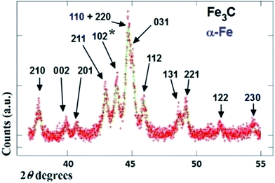
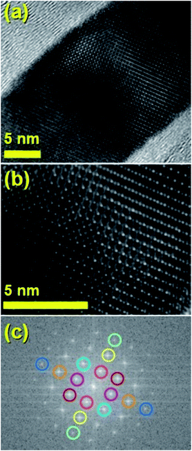
The typical cross sectional morphology of the radial structures produced by pyrolysis of 180 mg of ferrocene evaporated at 450 °C is shown in Fig. 1(a) and (b) using TEM analysis. Most notably the radial structures obtained in these conditions show a characteristic partial filling rate with a filling-crystal diameter of 20–30 nm. The Rietveld refinement of the XRD diffractogram in Fig. 2 allowed for the extraction of the relative abundance of the phases encapsulated inside the MWCNTs. Interestingly a large relative-abundance of single-crystalline Fe3C (23.7%) with space group Pnma was found, while only 3% of α-Fe with space group Im![[3 with combining macron]](https://www.rsc.org/images/entities/char_0033_0304.gif) m was present together with a very small quantity of γ-Fe (0.4%). Note that the relative abundance of the graphitic carbon associated with the 002 reflection of the CNTs-walls (see ESI Fig. S5†) was 72.9%. The unit cell parameters of Fe3C were a = 0.510 nm, b = 0.674 nm and c = 0.452 nm, while the unit cell parameters of α-Fe and γ-Fe were a = b = c = 0.286 nm, and 0.359 nm respectively. Such quantity of graphitic carbon is much higher with respect to that previously measured in the case of previous investigations in viscous boundary layer pyrolysis of ferrocene (50%). HRTEM investigations of the crystal structure of a typical Fe3C single crystal are shown in Fig. 3(a) and (b). In Fig. 3(c), the Fourier transform of the area in (b) allowed for the measurement of the reciprocal lattice reflections for the Fe3C single crystal and extraction of the lattice-spacing values in nm.
m was present together with a very small quantity of γ-Fe (0.4%). Note that the relative abundance of the graphitic carbon associated with the 002 reflection of the CNTs-walls (see ESI Fig. S5†) was 72.9%. The unit cell parameters of Fe3C were a = 0.510 nm, b = 0.674 nm and c = 0.452 nm, while the unit cell parameters of α-Fe and γ-Fe were a = b = c = 0.286 nm, and 0.359 nm respectively. Such quantity of graphitic carbon is much higher with respect to that previously measured in the case of previous investigations in viscous boundary layer pyrolysis of ferrocene (50%). HRTEM investigations of the crystal structure of a typical Fe3C single crystal are shown in Fig. 3(a) and (b). In Fig. 3(c), the Fourier transform of the area in (b) allowed for the measurement of the reciprocal lattice reflections for the Fe3C single crystal and extraction of the lattice-spacing values in nm.
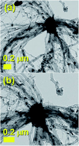 | ||
| Fig. 1 Transmission electron micrographs (a) and (b) of a small radial-structure with a core diameter of 0.2 micrometres. | ||
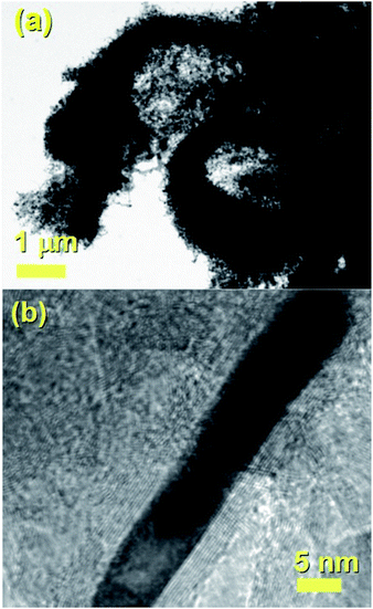
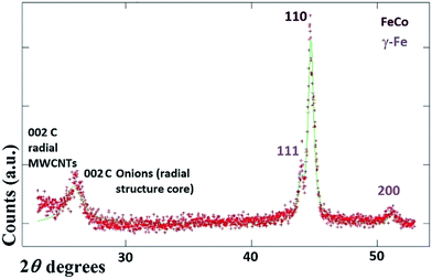
It would appear through the observation of the a- and c-crystal axis (100 and 001 reflections) that the crystals grow with a preferred orientation with an angle (of the a-axis) of approximately 60 degrees with respect to the hollow of the MWCNT. The list of reflections is reported in the caption of Fig. 3. Note that the phase identification of the α-Fe and γ-Fe could not be performed through HRTEM owing to the limited instrumental resolution. Further morphological and structural analysis was then performed using SEM (see Fig. S1 in ESI†) and TEM in the case of the radial structures filled with FeCo alloys. A typical example of the cross-sectional morphology of a radial structure observed at low magnification is shown in Fig. 4(a). Interestingly these structures appear to be characterized by a more pronounced branched-like morphology which is different with respect to that observed when only ferrocene is used as a precursor (Fig. 1). Further investigations at higher magnification revealed that also in this case the CNTs comprised in the radial structures are filled with small elongated crystals with a diameter of approximately 5–30 nm (Fig. 4(b) and ESI Fig. S2†). In addition, selective area electron diffraction (SAED) analysis of these structures confirmed that also in this case the encapsulated particles possess a single crystal arrangement (see inset in Fig. S2(I) in ESI†). The XRD analysis performed for the specific case of FeCo are shown in Fig. 5. The relative abundance of the phases extracted from the Rietveld refinement method were as follows: 84% of FeCo with space group Pm![[3 with combining macron]](https://www.rsc.org/images/entities/char_0033_0304.gif) m (excluding the carbon% and with unit cell parameters a = b = c = 0.285 nm database card 9004229 Crystallography Open Database) and 16% of γ-Fe with space group Fm
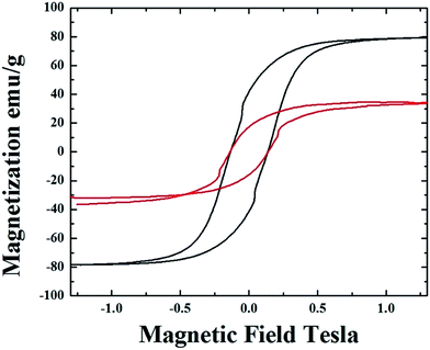
m (excluding the carbon% and with unit cell parameters a = b = c = 0.285 nm database card 9004229 Crystallography Open Database) and 16% of γ-Fe with space group Fm![[3 with combining macron]](https://www.rsc.org/images/entities/char_0033_0304.gif) m (excluding the carbon% with unit cell parameters a = b = c = 0.357 nm database card 9008469 Crystallography Open Database). The magnetic properties of the radial-structures were then investigated. The typical hysteresis loop of a powder comprising these structures is shown in Fig. 6. Large coercivity values of 0.140 T (1400 Oe) were serendipitously found in both types of samples whereas, a saturation magnetization of 30 emu g−1 was found for the radial CNTs structures filled with Fe3C (similar to that observed in ref. 29) and of 80 emu g−1 for the case of FeCo crystals.
m (excluding the carbon% with unit cell parameters a = b = c = 0.357 nm database card 9008469 Crystallography Open Database). The magnetic properties of the radial-structures were then investigated. The typical hysteresis loop of a powder comprising these structures is shown in Fig. 6. Large coercivity values of 0.140 T (1400 Oe) were serendipitously found in both types of samples whereas, a saturation magnetization of 30 emu g−1 was found for the radial CNTs structures filled with Fe3C (similar to that observed in ref. 29) and of 80 emu g−1 for the case of FeCo crystals.
The saturation magnetization in the first type of radial CNTs is much lower with respect to that expected in literature for bulk Fe3C (169 emu g−1). Rescaling the value of magnetization with respect to the % of ferromagnetic material gives a value of 110 emu g−1. Such value of magnetization is much higher with respect to that of 28 emu g−1 (56 emu g−1 when rescaled with respect to the ferromagnet% (ref. 29)) obtained in the case of radial structures produced in the previous report on viscous boundary layer CVS.29 A similar trend is found also in the case of γ-Fe/FeCo structures where the magnetization is low with respect to what would be expected for bulk FeCo (220 emu g−1) and assumes a value of 133 emu g−1 if rescaled to the FeCo (50.4%)/γ-Fe (9.6%) abundances. The relative abundances of 60% of whole FeCo/γ-Fe system and 40% of graphitic carbon were extracted by using the Rietveld refinement method. These observations suggest that the room-temperature magnetic properties of the radial structures produced in this work are not affected by the presence of the γ-Fe phase. Therefore a dependence of these properties on the single- or poly-crystal arrangement of the ferromagnet, on the magnetic domain arrangements or on the grain-boundary arrangement can not be excluded.
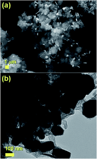
The growth mechanism of the radial structures was then investigated also in presence of mixed dichlorobenzene and ferrocene vapors. Cl radicals have been recently used to slow down the growth mechanism of CNTs in order to favor the process of Fe encapsulation and allow the achievement of high and continuous ferromagnetic filling rates. However the dynamics of such growth mechanism in the viscous boundary layers have not yet been investigated. In this specific case, the SEM analyses in Fig. 7(A) and the TEM micrograph in Fig. 7(B) (see also ESI Fig. S3†) revealed a change in the morphology of the radial structures, which appears to be characterized by thin walled carbon nanotubes filled with 100 nm to 2 micrometres long Fe3C crystals (see ESI Fig. S4 for VSM analyses†). Interestingly these radial-structures do not exhibit a central core feature but rather numerous branches. These observations suggest therefore that the homogeneous nucleation mechanism induced by the viscous boundary layer is strongly affected by the presence of Cl radicals. These radicals slow down the CNTs nucleation process by etching the catalyst particles and by removing carbon species through the formation of CCl4 species.
As shown in Fig. S4 ESI† the hysteresis loop measured in the case of these structures shows a remarkable decrease in the coercivity properties to the value of 580 Oe due to the increase of the particles diameter and length. Whilst the measured saturation magnetization of 35–37 emu g−1 is comparable to that shown in Fig. 6 for radial structures filled with Fe3C, α-Fe and γ-Fe crystals.
Conclusion
In conclusion we have reported the synthesis and characterization of radial-structures filled with large quantities of small Fe3C and FeCo crystals. The saturation magnetization is found to increase from 30 emu g−1 to 80 emu g−1 when the FeCo crystals are encapsulated inside the radial structures. Very large coercivity values of 0.140 T (1400 Oe) are found in both cases and can be associated to the small diameter of the encapsulated crystals. It seems clear that the encapsulation of these small crystals is induced by the high evaporation temperature of the precursors (higher with respect to that used in the previous reports). No magnetic effect is found from the γ-Fe phase. The effect of Cl radicals on the radial structure formation is also investigated and shows a dramatic variation in the morphology of the radial structures, with the disappearance of the central core and an increase of the encapsulated particles diameter. The attractive magnetic properties of these structures presented in this work show promise for numerous possible applications in magnetic data recording systems and electrodes, as well as microwave absorption, nanoinductors, permanent magnets, aerospace, and others.Acknowledgements
We acknowledge Prof. Gong Min for his continuous support and the National Natural Science Foundation of China Grant No. 11404227.Notes and references
- M. A. A. Elhissi, W. Ahmed, I. U. Hassan, V. R. Dhanak and A. D. Emanuele, J. Drug Delivery, 2012, 1, 837327 Search PubMed.
- R. Klingeler and R. B. Sim, Carbon Nanotubes for Biomedical Applications, Springer, Berlin Heidelberg, 2011, pp. 97–124 Search PubMed.
- A. Taylor, K. Lipert, K. Kramer, S. Hampel, S. Fussel, A. Meye, R. Klingeler, M. Ritschel, A. Leonhardt, B. Buchner and M. P. Wirth, J. Nanosci. Nanotechnol., 2009, 9, 5709 CrossRef CAS PubMed.
- B. Sitharaman and L. J. Wilson, Int. J. Nanomed., 2006, 1, 291 CAS.
- R. Lv, S. Tsuge, X. Gui, K. Takai, F. Kang, T. Enoki, J. Wei, J. Gu, K. Wang and D. Wu, Carbon, 2009, 47, 1141 CrossRef CAS.
- H. Terrones, F. Lopez-Urias, E. Munoz-Sandoval, J. A. Rodriguez-Manzo, A. Zamudio, A. L. Elias and M. Terrones, Solid State Sci., 2006, 8, 303 CrossRef CAS.
- F. C. Dillon, A. Bajpai, A. Koos, S. Downes, Z. Aslam and N. Grobert, Carbon, 2012, 50, 3674 CrossRef CAS.
- A. L. Danilyuk, A. L. Prudnikava, I. V. Komissarov, K. I. Yanushkevich, A. Derory, F. Le Normand, V. A. Labunov and S. L. Prischepa, Carbon, 2014, 68, 337 CrossRef CAS.
- S. Karmakar, S. M. Sharma, M. D. Mukadam, S. M. Yusuf and A. K. Sood, J. Appl. Phys., 2005, 97, 054306 CrossRef.
- C. S. Wang, B. M. Klein and H. Krakauer, Phys. Rev. Lett., 1985, 54, 1852 CrossRef CAS PubMed.
- P. Gorria, D. Martinez-Blanco, J. A. Blanco, A. Hernando, J. S. Garitaonandia, L. Fernandez Barquin, J. Campo and R. I. Smith, Phys. Rev. B: Condens. Matter Mater. Phys., 2004, 69, 214421 CrossRef.
- S. Groudeva-Zotova, R. Kozhuharova, D. Elefant, T. Muehl, C. M. Schneider and I. Moench, J. Magn. Magn. Mater., 2006, 306, 40 CrossRef CAS.
- D. Golberg, M. Mitome, C. Muller, C. Tang, A. Leonhardt and Y. Bando, Acta Mater., 2006, 54, 2567 CrossRef CAS.
- S. Hampel, A. Leonhardt, D. Selbmann, K. Biedermann, D. Elefant, C. Muller, T. Gemming and B. Buchner, Carbon, 2006, 44, 2316 CrossRef CAS.
- A. Leonhardt, M. Ritschel, R. Kozhuharova, A. Graffa, T. Muhl, R. Huhle, I. Monch, D. Elefant and C. M. Schneider, Diamond Relat. Mater., 2003, 12, 790 CrossRef CAS.
- C. Prados, P. Crespo, J. M. Gonzalez, A. Hernando, J. F. Marco, R. Gancedo, N. Grobert, M. Terrones, R. M. Walton and H. W. Kroto, Phys. Rev. B: Condens. Matter Mater. Phys., 2002, 65, 113405 CrossRef.
- J. F. Marco, J. R. Gancedo, A. Hernando, P. Crespo, C. Prados, J. M. Gonzalez, N. Grobert, M. Terrones, D. R. M. Walton and H. W. Kroto, Hyperfine Interact., 2002, 139, 535 CrossRef.
- F. Wolny, T. Muhl, U. Weissker, K. Lipert, J. Schumann, A. Leonhardt and B. Buchner, Nanotechnology, 2010, 21, 435501 CrossRef CAS PubMed.
- S. Hudziak, A. Darfeuille, R. Zhang, T. Peijs, G. Mountjoy, G. Bertoni and M. Baxendale, Nanotechnology, 2010, 21, 125505 CrossRef CAS PubMed.
- P. C. P. Watts, W. K. Hsu, D. P. Randall, V. Kotzeva and G. Z. Chen, Chem. Mater., 2002, 14, 4505–4508 CrossRef CAS.
- R. H. Baughman, C. X. Cui, A. A. Zakhidov, Z. Iqbal, J. N. Barisci and G. M. Spinks, et al., Science, 1999, 284, 1340–1344 CrossRef CAS PubMed.
- H. Lin, H. Zhu, H. Guo and L. Yu, Mater. Lett., 2007, 61, 3547–3550 CrossRef CAS.
- S. Noriaki, N. Masakazu and K. Takeyuki, Carbon, 2007, 45, 78–82 CrossRef.
- R. Lv, F. Kang, J. Gu, X. Gui, J. Wei, K. Wang and D. Wu, Appl. Phys. Lett., 2008, 93, 223105 CrossRef.
- R. Lv, F. Kang, W. Wang, J. Wei, J. Gu, K. Wang and D. Wu, Carbon, 2007, 45, 1433 CrossRef CAS.
- W. Wang, K. Wang, R. Lv, J. Wei, X. Zhang, F. Kang, J. Chang, Q. Shu, Y. Wang and D. Wu, Carbon, 2007, 45, 1105 CrossRef.
- S. Philippi, U. Weißker, T. Muhl, A. Leonhardt and B. Buchner, J. Appl. Phys., 2011, 110, 084319 CrossRef.
- F. S. Boi, G. Mountjoy, R. M. Wilson, Z. Luklinska, L. J. Sawiak and M. Baxendale, Carbon, 2013, 64, 351 CrossRef CAS.
- F. S. Boi, G. Mountjoy and M. Baxendale, Carbon, 2013, 64, 516 CrossRef.
- T. Peci and M. Baxendale, Carbon, 2015, 98, 519–525 CrossRef.
- C. Muller, D. Golberg, A. Leonhardt, S. Hampel and B. Buchner, Phys. Status Solidi A, 2006, 203, 1064–1068 CrossRef.
- F. S. Boi, S. Maugeri, J. Guo, M. Lan, S. Wang, J. Wen, G. Mountjoy, M. Baxendale, G. Nevill, R. M. Wilson, Y. He, S. Zhang and G. Xiang, Appl. Phys. Lett., 2014, 105, 243108 CrossRef.
- J. Guo, M. Lan, S. Wang, Y. He, S. Zhang and G. Xiang, et al., Phys. Chem. Chem. Phys., 2015, 17, 18159 RSC.
- F. S. Boi, J. Guo, S. Wang, Y. He, G. Xiang, X. Zhang and M. Baxendale, Chem. Commun., 2016, 52, 4195–4198 RSC.
- V. Likodimos, S. Glenis, N. Guskos and C. L. Lin, Phys. Rev. B: Condens. Matter Mater. Phys., 2003, 68, 045417 CrossRef.
Footnotes |
| † Electronic supplementary information (ESI) available. See DOI: 10.1039/c6ra27888d |
| ‡ These authors contributed equally to this work. |
| This journal is © The Royal Society of Chemistry 2017 |

