DOI:
10.1039/C6RA27805A
(Paper)
RSC Adv., 2017,
7, 11707-11718
Cf/C–SiC–MoSi2 composites with good ablation performance prepared via a two-step hydrothermal method
Received
6th December 2016
, Accepted 30th January 2017
First published on 16th February 2017
Abstract
Cf/C–SiC–MoSi2 composites were prepared via a simple hydrothermal method. The kinetics of the hydrothermal penetration process, the mechanical properties, and ablation behaviors of the composites were investigated. Results showed that the penetration activation energy was only 51.3 kJ mol−1. The flexural strength of the composites was 111.7 MPa. The Cf/C–SiC–MoSi2 composites exhibited good ablation properties after being exposed to plasma flame at 2300 °C. During the ablation, molten SiO2 could prevent carbon from oxidation. Moreover, the transformation from MoO2 to gaseous MoO3 consumed considerable amounts of oxygen and absorbed a large amount of heat, which prevented the composites from further ablation.
1. Introduction
For the development of aerospace technology, there are great challenges for achieving advanced thermal protection materials, especially for materials with high temperature performances over 2000 °C.1,2 Carbon/carbon (C/C) composites are regarded as desirable candidates for thermal protection materials because of their excellent properties such as high strength-to-weight ratio, excellent specific strength, and high thermal conductivity.3–5 However, the C/C composites are vulnerable to oxidation at elevated temperatures in aerobic environments, which seriously limits their application in advanced space systems.6
Introducing ultra-high temperature ceramics (UHTCs) into C/C composites has been considered as an effective way to improve the oxidation and ablation resistance.7,8 As is known, there have been significant advancement in refractory carbide and boride ceramics (e.g. ZrC, HfC, TaC, and ZrB2)-modified C/C composites. Composites, such as C/C–ZrC and C/C–ZrB2, show good ablation properties at high temperatures. However, C/C–UHTCs composites ablated at moderate to high temperatures have attracted less attention. MoSi2 is a type of intermetallic compound with a lower melting point (2030 °C) compared to UNTCs; however, it possesses excellent oxidation resistance, which is why it is widely applied in the coating materials for C/C composites.9,10 Therefore, the introduction of MoSi2 into C/C composites might play an important role in the low-temperature ablation area (around 2000 °C). Recently, research has proved that MoSi2 is an ideal candidate for enhancing the ablation properties of the C/C composites.11,12 Hao et al. developed Cf/MoSi2–SiC–C-based composites by infiltrating Mo–Si–Ti/Al mixed powder into a porous C/C preform. There were SiC (43–76 wt%), MoSi2, and ceramic phases containing Ti/Al in the composites. The Cf/C–MoSi2–SiC composites showed excellent ablation properties. The C/C–MoSi2 composites are beneficial for improving the ablation performance of C/C composites and broadening the ablation materials system. That is very important for the development of the aviation and space industry.
In previous studies, the C/C–UHTCs composites were fabricated via many approaches such as precursor infiltration and pyrolysis,13–16 reactive melt infiltration,17–20 chemical vapor infiltration,21–23 and slurry/powder infiltration.8,24 However, these methods usually require complicated experimental facilities, high production costs, high temperatures or special shape of preforms. Moreover, during the preparation, carbon fibers may be damaged due to chemical reactions, which reduce the mechanical performance of the composites. Over the years, hydrothermal treatment has attracted significant attention because of its characteristics such as being environment-friendly, require mild reaction conditions, provide increased reaction rates, and results in considerable productivity.25–27 Moreover, hydrothermal process can provide a hyperbaric environment. It is beneficial for the particles and hydrothermal products to infiltrate into cracks and pores of C/C composites. With the help of microwave hydrothermal process, C/C–ZrC composites with a ZrC rich surface layer were prepared by Li et al.28 ZrC particles were homogeneously dispersed in the carbon matrix. The linear and mass ablation rates of the composites were only about 3.2 μm s−1 and 1.5 mg cm−2 s−1 after being exposed to an oxyacetylene torch at 3000 °C for 60 s, respectively. Cao and Mi et al.29 introduced Al(PO3)3 into porous C/C composites via a microwave hydrothermal method to improve the low-temperature oxidation resistance of the C/C composites. The results showed that after oxidation at 700 °C in air for 10 hours, the mass loss of the modified composites was only 11 mg cm−2. Thus, the hydrothermal process should be an efficient way to fabricate C/C–UHTCs composites.
In this study, Cf/C–SiC–MoSi2 composites were fabricated via a two-step hydrothermal method. First, SiC and MoSi2 particles were introduced into porous and low-density C/C composites through the high pressure of hydrothermal treatment. Then, the composites containing SiC and MoSi2 were densified via hydrothermal carbonization. The penetration kinetics of SiC and MoSi2, the microstructure, and ablation resistance of the composites were investigated. The ablation mechanism of the composites was also studied.
2. Experiments
2.1 Fabrication of the composites
The preforms (PAN-based carbon fiber, T300) were cut into small specimens (Φ35 × 10 mm) and densified to about 0.57 g cm−3 via a hydrothermal treatment. The densification procedure was executed at 200 °C for 24 h using 1.5 mol L−1 glucose aqueous solutions as the media. After this, the porous and low density C/C composites were ultrasonically cleaned with distilled water, and then dried at 100 °C for 4 h.
SiC (2 g, particle size 0.5–0.7 μm, purity ≥ 99.9%) and MoSi2 (2 g, particle size 0.5–2 μm, purity ≥ 99%) were dispersed in 40 mL water–ethanol mixture (Vwater/Vethanol = 3/1) via ultrasonication for 30 min (the ultrasonic power was set at 400 W), and the mixture was magnetically stirred for 24 h. The composites were placed into a 100 mL Teflon autoclave and immersed with the SiC and MoSi2 suspension. The Teflon autoclave was sealed and heated to the set temperatures for definite times (Fig. 1). During this process, the Teflon autoclave was continuously rotated using an electrical machine. The contents of SiC and MoSi2 in the composites were controlled by the hydrothermal infiltration times and cycles.
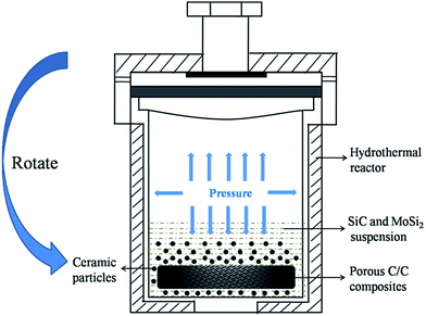 |
| | Fig. 1 Schematic of the hydrothermal penetration process. | |
After infiltrating SiC and MoSi2 particles into the C/C composites, another typical cycle of the hydrothermal process was carried out to improve the density of the composites and reduce the defects among the carbon fibers and ceramic matrix of the composites. The composites containing ceramic particles were soaked in a 1 mol L−1 glucose aqueous solution. They were then hydrothermally treated at 200 °C for 12 h. This soaking followed by a later hydrothermal treatment was repeated 12 times to obtain dense composites. The composites were polished after every hydrothermal treatment. Finally, the composites were heat-treated at 1200 °C for 2 h in an argon atmosphere to fully carbonize. They were named as Cf/C–SiC–MoSi2 composites.
2.2 Ablation test
The ablation test of the specimens was carried out using a plasma generator (Multiplaz, 3500). During the test, the ablation angle was 90°. The distance between the specimen surface and the gun tip was maintained at 10 mm, and the inner diameter of the plasma generator tip was about 2 mm. The work current and voltage of the plasma generator were 6 A and 160 (±1) V, respectively. The maximum temperature of the ablation center surface of the specimen reached 2300 °C, which was measured by an optical pyrometer. Three specimens were exposed to the plasma flame for 60 s. The average linear and mass ablation rates of the composites were calculated using eqn (1) and (2):| |
 | (1) |
| |
 | (2) |
where Rl is the linear ablation rate, Δd is the change in the sample thickness at the most serious ablated region before and after ablation, Rm is the mass ablation rate, Δm is the sample's mass change before and after ablation, s is the surface area of the crater, and t is the ablation time.
2.3 Characterization
The open porosity and bulk density of the composites were investigated using a mercury injection apparatus (micromeritics, Auto pore IV 9500). Twenty-five points on the surface and cross-section of the composites were randomly selected to measure Si/Mo atomic ratio by an X-ray fluorescent analyzer (XRF, HORIBA XGT-7200). The phase compositions of the composites before and after ablation were characterized via X-ray diffraction (XRD, Rigaku D/max-3C). The microstructure and morphology of the materials were investigated via scanning electron microscopy (SEM, FEI-Q45) combined with energy dispersive spectroscopy (EDS). The flexural strength was obtained using a 3-point-bending fixture (materials testing machine, WDW-50H) with three bar specimens (35 × 10 × 5 mm), and the crosshead speed was set at 0.5 mm min−1.
3. Results and discussion
3.1 Penetration process
The SEM image of the Cf/C–SiC–MoSi2 composites after the hydrothermal penetration is shown in Fig. 2a. The fibers were wrapped by many small solids. As observed from the magnified image, some microspheres and particles adhered to the surface of the carbon fibers. By EDS analysis (Fig. 2b), it was observed that the microspheres are composed of C and O. This indicated that these were carbonized glucose generated during the first hydrothermal carbonization process before the introduction of ceramic particles. As for the particles on the fibers, the small-sized ones were SiC, whereas the larger ones were MoSi2 according to the corresponding EDS spectra (Fig. 2c and d). These conclusions prove that the ceramics could be introduced into porous C/C composites via a hydrothermal process.
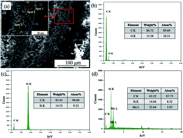 |
| | Fig. 2 SEM image and EDS analysis of the Cf/C–SiC–MoSi2 composites after the hydrothermal penetration process ((a) SEM image; (b), (c), and (d) EDS spectra of spots 1, 2, and 3 shown in (a)). | |
To further account for the feasibility of hydrothermal penetration, penetration kinetics of this method have been discussed. Fig. 3a shows the variable relationship between the penetration quantity of the ceramic particles and the hydrothermal time at different temperatures. With the increasing temperature, the penetration quantity grew at the same penetration time. This is because an increase in temperature leads to a rapid increase in the system pressure (Fig. 3b) and diffusion coefficient of the ceramic particles. The ceramic particles were promptly infiltrated into the matrix of porous C/C composites. As shown in Fig. 3c, there is a linear relationship between the penetration quantity and the square root of time. This illustrates that the infiltration of SiC and MoSi2 is controlled by their diffusion rate. The penetration quantity of the ceramic particles (X) can be calculated using eqn (3):
| |
 | (3) |
where
D and
t are the diffusion coefficient and penetration time, respectively.
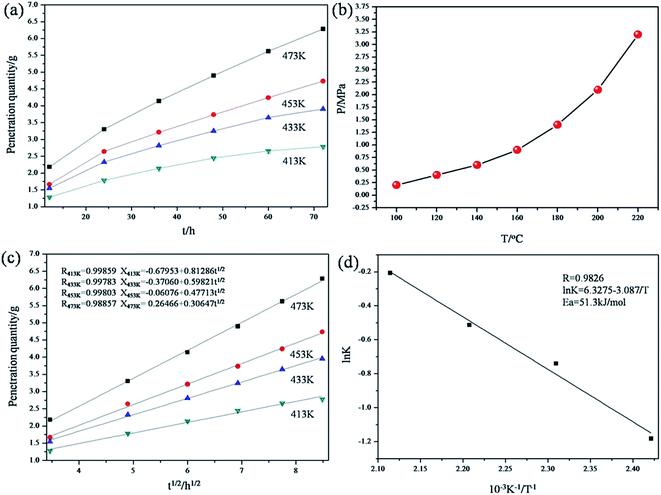 |
| | Fig. 3 Kinetic models of the penetration process ((a) variable relationship between the penetration quantity and hydrothermal time; (b) curve of the system pressure and temperature; (c) variable relationship between the penetration quantity and the square root of time; (d) curve of ln![[thin space (1/6-em)]](https://www.rsc.org/images/entities/char_2009.gif) K−1/T). K−1/T). | |
Based on the data shown in Fig. 3c, the relation curve of ln![[thin space (1/6-em)]](https://www.rsc.org/images/entities/char_2009.gif) K and 1/T was acquired (Fig. 3d) via calculation. K is a constant at a certain temperature, and it can be calculated from the following equation:
K and 1/T was acquired (Fig. 3d) via calculation. K is a constant at a certain temperature, and it can be calculated from the following equation:
Thus, K can be also expressed by eqn (5) from the abovementioned equations.
| |
 | (5) |
After fitting, it was observed that a linear relationship also exists between ln![[thin space (1/6-em)]](https://www.rsc.org/images/entities/char_2009.gif) K and 1/T. In addition, the relationship is well represented by the Arrhenius model (relevant coefficient = 0.9826).
K and 1/T. In addition, the relationship is well represented by the Arrhenius model (relevant coefficient = 0.9826).
Thus, the activation energy (Ea) of the penetration process can be acquired using eqn (7), which was deduced from eqn (5) and the Arrhenius equation (eqn (6)):
| |
 | (6) |
| |
 | (7) |
where
T is the penetration temperature.
D0,
K0, and
R are constants.
Eventually, Ea was calculated to be 51.3 kJ mol−1, which is much lower than that of some complex chemical reactions. Therefore, the introduction of SiC and MoSi2 into porous C/C composites via a hydrothermal treatment was quite possible. Clearly, the preparation of the composites at 200 °C was most efficient. The following Cf/C–SiC–MoSi2 composites mentioned in this study were penetrated at 200 °C.
3.2 Composition and microstructure
Fig. 4a shows the macroscopic morphology of the sample after densification. No open pores and cracks are present on the surface of the Cf/C–SiC–MoSi2 composites. The original defects in the C/C composites were effectively filled via hydrothermal carbonized glucose (inset in Fig. 4a). As can be seen from the XRD result (Fig. 4b), the composites consisted of SiC, MoSi2, and C, which is in well accordance with the experimental design.
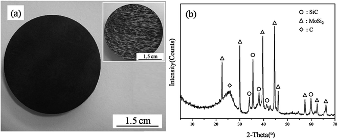 |
| | Fig. 4 Macroscopic image and surface XRD pattern of the as-prepared composites ((a) macro-image; inset shows the image of the carbon preform (b) XRD pattern). | |
The detailed composition and physical properties of the Cf/C–SiC–MoSi2 composites are shown in Table 1. The whole bulk density of these was about 1.6 g cm−3. The Si/Mo atomic ratio was 5![[thin space (1/6-em)]](https://www.rsc.org/images/entities/char_2009.gif) :
:![[thin space (1/6-em)]](https://www.rsc.org/images/entities/char_2009.gif) 1. According to the Si to Mo mole ratio, the SiC to MoSi2 mole ratio was 3
1. According to the Si to Mo mole ratio, the SiC to MoSi2 mole ratio was 3![[thin space (1/6-em)]](https://www.rsc.org/images/entities/char_2009.gif) :
:![[thin space (1/6-em)]](https://www.rsc.org/images/entities/char_2009.gif) 1. Therefore, the mass ratio of SiC/MoSi2 was set at 4/5, whereas the total mass fraction of the SiC and MoSi2 particles was about 46.6% (eqn (8)). The volume percentage of MoSi2 and SiC (VSiC/MoSi2) was 14.2%, which were calculated using eqn (9).30
1. Therefore, the mass ratio of SiC/MoSi2 was set at 4/5, whereas the total mass fraction of the SiC and MoSi2 particles was about 46.6% (eqn (8)). The volume percentage of MoSi2 and SiC (VSiC/MoSi2) was 14.2%, which were calculated using eqn (9).30
| |
 | (8) |
| |
 | (9) |
where
MC/Filler,
MFelt, and
MFinal are the mass of the carbon fiber felts after the hydrothermal penetration, the carbon fiber felts, and the final composites, respectively.
DC/Filler and
DFelt are the densities of the carbon fiber felts after the hydrothermal penetration process and carbon fiber felts, respectively;
DSiC/MoSi2 is the mean density of the SiC and MoSi
2 particles.
Table 1 Details of the as-prepared Cf/C–SiC–MoSi2 composites
| Materials |
Bulk density (g cm−3) |
Si/Mo atomic ratio (mol%) |
SiC/MoSi2 mass ratio |
Porosity (%) |
SiC/MoSi2 mass fraction (%) |
SiC/MoSi2 volume percentage (%) |
| Cf/C–SiC–MoSi2 |
1.6 |
5/1 |
4/5 |
12.8 |
46.6 |
14.2 |
Fig. 5 displays the microstructure and EDS spectra of the Cf/C–SiC–MoSi2 composites. Compact and homogeneous surface structure without any defects was achieved via a two-step hydrothermal process (Fig. 5a). There were no obvious micropores and cracks in the ceramic matrix. In addition, no gaps existed at the interfaces between the carbon fibers and matrixes according to the cross-section SEM image (Fig. 5b). The structure was quite different from that shown in Fig. 2a, which is attributed to the second hydrothermal process. The carbonization of the glucose solution occurred in the holes among carbon fibers, carbon matrix, and ceramic matrix. Therefore, the pyrolytic carbon (PyC) would effectively decrease the gaps after multiple hydrothermal carbonization and heat treatment processes. EDS analysis showed that the particles among the carbon fibers are composed of C, Si, and Mo. Combined with the XRD result, it can be confirmed that the defects were filled by SiC–MoSi2 hybrid ceramic and plentiful carbon. In contrast to Fig. 2b, O was not found. This is because that the oxygen-containing functional groups (such as hydroxyl and carboxyl31) were removed via heat treatment.
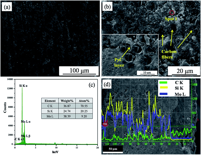 |
| | Fig. 5 SEM image and EDS results of the Cf/C–SiC–MoSi2 composites ((a) surface image; (b) cross-section image; inset shows a SEM image at high magnification; (c) the EDS spectrum of spot 1 in (b); (d) cross-section elemental distributions of line-scanning). | |
From the cross-section elemental distributions of line-scanning, the variations of C, Si, and Mo are shown in Fig. 5d. The distribution of Mo, representing MoSi2, in the Cf/C–SiC–MoSi2 composites was quite deep because of the high pressure of the hydrothermal penetration process. The deep penetration depth of the SiC–MoSi2 hybrid ceramics was essential for the good anti-ablation performance. They would react with oxygen to form protective components during the ablation, preventing the matrices from corrosion.
According to the XRF, XRD, SEM, and EDS results, it can be demonstrated that the SiC–MoSi2 hybrid ceramics could be penetrated into low-density C/C composites via hydrothermal penetration. The Cf/C–SiC–MoSi2 composites with compact structure were obtained after the densification process.
3.3 Mechanical properties
Fig. 6 shows the typical stress–displacement curve of the Cf/C–SiC–MoSi2 composites after a mechanical test. The flexural strength of the Cf/C–SiC–MoSi2 composites was 111.7 MPa. In the early stages of the loading, elastic deformation occurred on the composites, and a linear relationship between displacement and stress was presented. After the fracture force reached the maximum, the stress gradually decreased with the increasing displacement, indicating that the Cf/C–SiC–MoSi2 composites exhibit pseudo-plastic fracture behavior.
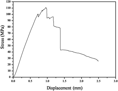 |
| | Fig. 6 Stress–displacement curve of the Cf/C–SiC–MoSi2 composites during the flexural test. | |
Morphological analysis of the fracture surfaces of the composites are presented in Fig. 7. It can be seen that many carbon fiber bundles were pulled out from the matrix after the flexural strength test (Fig. 7a), which may be caused by the following reason. The great mechanical properties of the composites largely depend on the fiber-matrix and the fiber-matrix–filler interfacial adhesion because load transfer from the matrix to the fibers would require good bonding at the interfaces.32 In this study, the carbon fibers were covered by hydrothermal carbon and SiC–MoSi2 hybrid ceramic. However, the ceramic matrix did not bind well with the fiber surfaces. Moreover, the bonding between them was not chemical but simple physical adherence after the hydrothermal penetration. Consequently, when the cracks spread to the fiber/ceramic interface during the test, carbon fibers tended to be easily pulled out from the matrix. Hence, a pseudo-plastic fracture behavior of the Cf/C–SiC–MoSi2 was observed. Moreover, the pullout of the carbon fibers, crack propagation (Fig. 7b), and fiber debonding (Fig. 7c and d) absorbed a great amount of energy, which was beneficial for improving the mechanical properties of the composites.
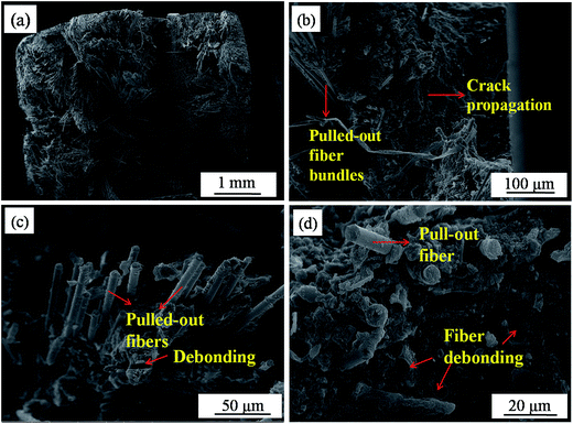 |
| | Fig. 7 SEM images of the fracture surfaces of the composites after the flexural strength test ((a) fracture surface; (b) crack propagation; (c) fiber pullout; and (d) fiber debonding). | |
3.4 Ablation behavior of the composites
The ablation properties of the prepared Cf/C–SiC–MoSi2 and pure C/C composites are listed in Table 2. The mass and linear ablation rates of the Cf/C–SiC–MoSi2 composites were only 2.28 mg cm−2 s−1 and 4.62 μm s−1, respectively, after the ablation for 60 s. Compared to the pure C/C composites, the ablation resistance of the C/C–SiC–MoSi2 composites was significantly improved. Fig. 8 reveals the image and surface XRD patterns in different areas of the Cf/C–SiC–MoSi2 composites after the ablation test. The surface was covered by a white layer. During the ablation test, the penetrated SiC and MoSi2 ceramics were oxidized to the other oxides of silicon and molybdenum. According to the XRD analysis results (Fig. 8b), the layer was a mixture of SiC, MoSi2, Mo5Si3, MoO2, and SiO2. In addition, the discovery of the peaks for MoSi2 and SiC indicated that the ceramics were not completely oxidized in a short ablation time.
Table 2 Ablation properties of the prepared Cf/C–SiC–MoSi2 and pure C/C composites
| Composites |
Mass ablation rate (mg cm−2 s−1) |
Linear ablation rate (μm s−1) |
| C/C |
8.71 |
16.24 |
| Cf/C–SiC–MoSi2 |
2.28 |
4.62 |
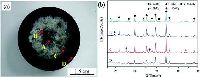 |
| | Fig. 8 Macro-image and surface XRD patterns of the as-prepared Cf/C–SiC–MoSi2 composites after the ablation test at 2300 °C for 60 s ((a) macro-photograph; (b) XRD patterns in different areas). | |
To research the ablation behavior of the Cf/C–SiC–MoSi2 composites ablated by plasma flame, the morphologies of different ablation regions were observed by SEM. Fig. 9a–c shows the backscattered electron images and EDS results of the ablation center area. Many particles were found around the carbon fibers. On the other hand, the fibers were still ablated into a needle-like shape (inset in Fig. 9b), indicating that the particles had not protected the carbon fibers, as expected. Moreover, serious ablation occurred in the center area. The number of particles shown in Fig. 9a was much less than that shown in Fig. 9b. The heat flow could blow the particles in all directions. When the flame direction was parallel to the axial plane of the fibers, the ablation temperature was relatively lower and the scouring force was weaker.14 Therefore, the fibers parallel to the plasma flame suffered less damage than those perpendicular to the plasma flame.
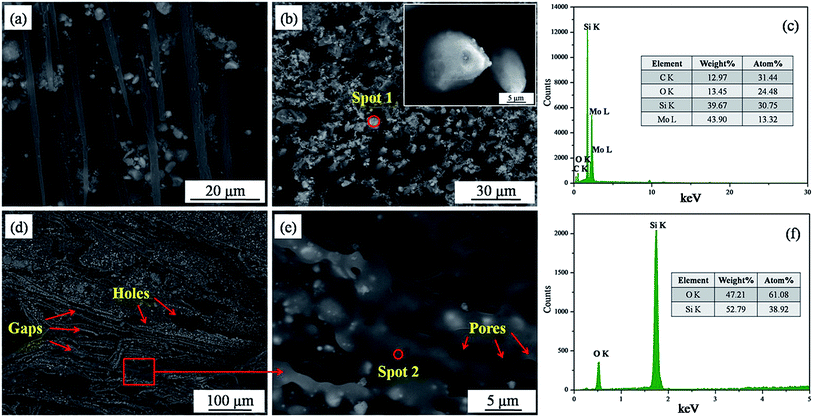 |
| | Fig. 9 Backscattered electron images and EDS spectra in different ablation areas ((a) and (b) images in ablation center marked as A in Fig. 8a; (c) EDS spectrum of spot 1 in (b); (d) and (e) SEM images in the central boundary area marked as B in Fig. 8a; (f) EDS spectrum of spot 2 in (d)). | |
By EDS analysis (Fig. 9c), it was observed that the particles are composed of Si, Mo, O, and C. Combined with the XRD result (Fig. 8b(A)), it was observed that they were unreacted MoSi2, SiC, and some oxidative products. Both MoSi2 and SiC can be oxidized to SiO2 liquids. The temperature in this area was up to 2300 °C and the boiling point of SiO2 was 2230 °C;33 thus, the molten SiO2 layer could be blown away by the strong plasma flame. This explains why SiO2 was not observed in the ablation center.
Fig. 9d and e show the microstructure of the central boundary area marked as B in Fig. 8a. The morphology of this area was quite different from that of A. Although the structure was also loose, the surface of the carbon fibers was covered with a molten glass layer. From the magnified image (Fig. 9e), pores were found on the surface of the glass layer, which was attributed to the escape of gases including CO2, CO, SiO2, SiO, etc. EDS showed that the molten glass was composed of Si and O, confirming that it was SiO2. The temperature and scouring force of the central boundary area was lower; hence, SiO2 played a positive role in enhancing the ablation resistance.
In the transition area, a new layer on the surface of the composites was observed (Fig. 10a). No bare fibers were found in this area, and the layer protected the carbon fibers and matrix well. Fig. 10b shows the morphology of the layer at higher magnification. As can be seen, the layer is made up of platy grains on the surface and small particles in the depth. The EDS spectrum (inset in Fig. 10b) of these platy grains demonstrated that they are composed of Mo, O, and very small amounts of Si. Combined with XRD (Fig. 8b(C)), it could be determined that the formed platy grains are MoO2. MoO2 was generated from the slight oxidation of MoSi2.34 As is known, the anti-oxidation property of MoO2 was not good. However, MoO2 can be easily oxidized to MoO3.35 This process consumes parts of oxygen gas and decreases the erosion of plasma flame to carbon. Moreover, the volatilization of MoO3 would take the heat away, which was beneficial for the ablation performance of the Cf/C–SiC–MoSi2 composites. The EDS map of Fig. 10b displays a layer containing abundant Si in addition to Mo and O. According to chemical reaction mechanism (eqn (9)), Si came from the SiO2 phase. SiO2 and other silicide in this area were absolutely good for ablation.
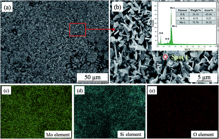 |
| | Fig. 10 Backscattered electron images and EDS analysis in the transition area ((a) SEM image; (b) SEM image at high magnification; inset shows the EDS spectrum of spot 1 in (b); (c), (d) and (e) EDS mapping of Mo, Si and O corresponding to (b), respectively). | |
Fig. 11 presents the SEM images of the brim area. As can be seen, the structure of the composites in this area was compact as a whole. However, there were some cracks on the surface of this area (Fig. 11b), which may be caused by the mismatch of the CTE between the ceramics and carbon materials. Beyond this, molten glass existed in small quantities (Fig. 11c). It can be speculated that the erosion and oxidation of the matrix was not serious, mainly, because of the temperature gradient on the surface of the composites during the ablation. The temperature and flow in this area were the lowest compared to those in others, such that the corrosion attack from the plasma flame was slight.
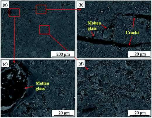 |
| | Fig. 11 Backscattered electron images in the brim area ((a) SEM image; (b), (c), and (d) SEM images at high magnification). | |
3.5 Ablation mechanism
Ablation is an erosive phenomenon, which is the removal of material by the combination of thermomechanical, thermochemical, and thermophysical processes. This was caused by the high temperature, pressure, and velocity of the hot gases resulting from combustion.36 The ablation of the Cf/C–SiC–MoSi2 composites is a complex process involving chemical erosion and mechanical denudation. Through the abovementioned analysis, the possible reactions occurring during the plasma ablation process are shown as follows:| | |
5MoSi2(s) + 7O2(g) → Mo5Si3(s) + 7SiO2(l)
| (10) |
| | |
MoSi2(s) + 3O2(g) → MoO2(s) + 2SiO2(s)
| (11) |
| | |
2MoO2(s) + O2(g) → 2MoO3(g)
| (12) |
| | |
SiC(s) + O2(g) → SiO(g) + CO(g)
| (13) |
| | |
2SiC(s) + 3O2(g) → 2SiO2(l) + 2CO(g)
| (14) |
| | |
SiC(s) + 2O2(g) → SiO2(l) + CO2(g)
| (15) |
| | |
C(s) + O2(g) → CO2(g)
| (17) |
| | |
2C(s) + O2(g) → 2CO(g)
| (18) |
| | |
C(s) + CO2(g) → 2CO(g)
| (19) |
The schematic of the ablation mechanism of the Cf/C–SiC–MoSi2 composites is shown in Fig. 12. When the ablation test was carried out, the oxidative gases reacted with the composites. In particular, in the ablation center, thermochemical erosion occurred according to eqn (10)–(19). MoSi2 and SiC rapidly transformed into Mo5Si3, SiO2, MoO2, etc. via oxidation reactions. However, the oxidative products were blown away by the thermomechanical denudation, whereas the gases (SiO2, SiO, and MoO2) evaporated due to high temperature. The carbon fibers and matrix did not receive enough protection from the ceramics, and they were heavily corroded. The linear and mass ablation rates of the Cf/C–SiC–MoSi2 composites were mostly obtained from this area. The molten SiO2 was blown out of the ablation center by strong scouring force. In the central boundary and transition areas, SiO2 could cover the fibers to prevent them from ablation. Large amounts of MoO2 were discovered in the transition area due to the oxidation of MoSi2 (eqn (11)) in a short time. Partial MoO2 would turn into gaseous MoO3 (reaction (12)). This process absorbed a significant amount of heat, which was beneficial for the ablation performance. The temperature and mechanical force in the brim area were weaker; thus, the structural damage was not serious.
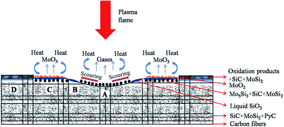 |
| | Fig. 12 Schematic of the ablation mechanism of the Cf/C–SiC–MoSi2 composites. | |
Based on the abovementioned analysis, the ablation mechanism of the composites was mainly controlled by the oxidation reactions and mechanical denudation. The good ablation resistance can be explained by the following reasons. (I) Cf/C–SiC–MoSi2 composites prepared via the two-step hydrothermal method had a compact structure and offered few active sites for the oxidation reactions at the interfaces. Moreover, the fibers were not damaged under the mild preparation conditions. (II) MoSi2 is a promising intermetallic material for high temperature applications. It possesses a high elastic modulus of 384 GPa and a hardness of 13 GPa.37 The introduction of MoSi2 into the C/C composites improved the strength of the composites and decreased the mechanical denudation during the ablation. (III) The oxidative products were blown away by the high-velocity plasma flame. The protection from the antioxidant materials was insufficient. However, with the ablation time extension, the ceramics matrix could provide enough MoSi2 and SiC to prevent carbon from ablation. (IV) The oxidation of MoSi2 and SiC could generate molten SiO2 glass continuously at high temperatures. The SiO2 filled the defects on the surface of the composites and acted as a barrier between carbon and oxidizing atmosphere. SiO2 greatly reduced the oxidized loss of the C/C composites due to its low oxygen diffusivity. (V) The oxidation of MoO2 would consume large amounts of oxygen. Consequently, MoO2 was regarded as an oxygen consumption additive to protect the composites from further ablation. (VI) The generation of large amounts of gases (CO2, CO, SiO, and MoO3) during the ablation absorbed heat from the flame and reduced the erosive attack on carbon fibers, which was also beneficial for the ablation resistance.
4. Conclusions
To improve the ablation resistance of the C/C composites, Cf/C–SiC–MoSi2 composites, with a density of 1.6 g cm−3, were prepared via a simple two-step hydrothermal method. The penetration activation energy was 51.3 kJ mol−1, which indicated that the introduction of ceramics into C/C composites via the hydrothermal treatment was possible. The flexural strength of the composites was 111.7 MPa. The fiber pull out and cracks deflection led to good mechanical performance. The mass and linear ablation rates of the Cf/C–SiC–MoSi2 composites were 2.28 mg cm−2 s−1 and 4.62 μm s−1, respectively, after being exposed to the plasma flame for 60 s. The good ablation resistance of the composites was attributed to the formation of molten SiO2 on the fiber surface, and SiO2 acted as a barrier to prevent carbon from oxidation. In addition, MoO2 was detected, and its oxidization to gaseous MoO3 absorbed a large amount of heat, which was good for ablation properties.
Acknowledgements
This work was supported by the National Natural Science Foundation of China (51272146), the Scientific Research Innovation Team Foundation of Shaanxi Province (2013KCT-06), and the Natural Science Foundation of Shaanxi Province (2015JM5251).
References
- X. T. Li, J. L. Shi, G. B. Zhang, H. Zhang, Q. G. Guo and L. Liu, Effect of ZrB2 on the ablation properties of carbon composites, Mater. Lett., 2006, 60, 892–896 CrossRef CAS.
- C. Y. Li, K. Z. Li, H. J. Li and H. B. Ouyang, Ablation resistance and thermal conductivity of carbon/carbon composites containing hafnium carbide, Corros. Sci., 2013, 75, 169–175 CrossRef CAS.
- E. Fitzer and L. M. Manocha, Carbon reinforcements and carbon/carbon composites, Springer, Berlin, 1998, pp. 250–319 Search PubMed.
- G. Savage, Carbon–carbon composites, Chapman & Hall, London, 1993, pp. 331–357 Search PubMed.
- E. Fitzer, The future of carbon–carbon composites, Carbon, 1987, 25, 163–190 CrossRef CAS.
- K. T. Wang, L. Y. Cao, J. F. Huang and J. Fei, A mullite/SiC oxidation protective coating for carbon/carbon composites, J. Eur. Ceram. Soc., 2013, 33, 191–198 CrossRef CAS.
- D. D. Jayaseelan, R. G. Sa, P. Brown and W. E. Lee, Reactive infiltration processing (RIP) of ultra high temperature ceramics (UHTC) into porous C/C composite tubes, J. Eur. Ceram. Soc., 2011, 31, 361–368 CrossRef CAS.
- S. F. Tang, J. Y. Deng, S. J. Wang, W. C. Liu and K. Yang, Ablation behaviors of ultra-high temperature ceramic composites, Mater. Sci. Eng., A, 2007, 465, 1–7 CrossRef.
- J. F. Huang, B. Wang, H. J. Li, M. Liu, L. Y. Cao and C. Y. Yao, A MoSi2/SiC oxidation protective coating for carbon/carbon composites, Corros. Sci., 2011, 53, 834–839 CrossRef CAS.
- L. Zhang, Q. G. Fu, T. Y. Liu and B. Y. Tan, In situ PIP-SiC NWs-toughened SiC–CrSi2–Cr3C2–MoSi2–Mo2C coating for oxidation protection of carbon/carbon composites, J. Alloys Compd., 2016, 675, 348–354 CrossRef.
- Z. H. Hao, W. Sun, X. Xiong, Z. K. Chen and Y. L. Wang, Effects of Ti/Al addition on the microstructures and ablation properties of Cf/C–MoSi2–SiC composites, J. Eur. Ceram. Soc., 2016, 36, 457–464 CrossRef CAS.
- L. Y. Cao, Z. Bai, J. F. Huang, H. B. Ouyang, C. Y. Li, B. Y. Wang and C. Y. Yao, Fabrication of gradient C/C–SiC–MoSi2 composites with enhanced ablation performance, Ceram. Int., 2016, 42, 12289–12296 CrossRef CAS.
- C. H. Ma, L. J. Guo, H. J. Li, W. L. Tan, T. Duan, N. K. Liu and M. Y. Zhang, Effects of high-temperature annealing on the microstructures and mechanical properties of C/C–ZrC–SiC composites prepared by precursor infiltration and pyrolysis, Mater. Des., 2016, 90, 373–378 CrossRef CAS.
- L. Xue, Z. A. Su, X. Yang, D. Huang, T. Yin, C. C. Liu and Q. Z. Huang, Microstructure and ablation behavior of C/C–HfC composites prepared by precursor infiltration and pyrolysis, Corros. Sci., 2015, 94, 165–170 CrossRef CAS.
- B. Feng, H. J. Li, Y. L. Zhang, L. Liu and M. Yan, Effect of SiC/ZrC ratio on the mechanical and ablation properties of C/C–SiC–ZrC composites, Corros. Sci., 2014, 82, 27–35 CrossRef CAS.
- C. X. Liu, Z. A. Su, Q. Z. Huang, J. X. Chen, X. Yang, L. X. Cao, T. Yin and P. Zhong, Ablation behavior of ZrC–SiC coated C/C–ZrC–SiC composites prepared by precursor infiltration pyrolysis combined with reactive melt infiltration, J. Alloys Compd., 2014, 597, 236–242 CrossRef CAS.
- Y. Zeng, X. Xiong, G. D. Li, Z. K. Chen, W. Sun and D. N. Wang, Microstructure and ablation behavior of carbon/carbon composites infiltrated with Zr–Ti, Carbon, 2013, 54, 300–309 CrossRef CAS.
- C. X. Liu, L. X. Cao, J. X. Chen, L. Xue, X. Tang and Q. Z. Huang, Microstructure and ablation behavior of SiC coated C/C–SiC–ZrC composites prepared by a hybrid infiltration process, Carbon, 2013, 65, 196–205 CrossRef CAS.
- Z. J. Dong, S. X. Liu, X. K. Li, A. Westwood, G. M. Yuan, Z. W. Cui and Y. Cong, Influence of infiltration temperature on the microstructure and oxidation behavior of SiC–ZrC ceramic coating on C/C composites prepared by reactive melt infiltration, Ceram. Int., 2015, 41, 797–811 CrossRef CAS.
- Y. G. Tong, S. X. Bai, Q. H. Qin, H. Zhang and Y. C. Ye, Effect of infiltration time on the microstructure and mechanical properties of C/C–SiC composite prepared by Si–Zr10 alloyed melt infiltration, Ceram. Int., 2015, 41, 4014–4020 CrossRef CAS.
- Y. G. Tong, S. X. Bai and K. Chen, C/C–ZrC composite prepared by chemical vapor infiltration combined with alloyed reactive melt infiltration, Ceram. Int., 2012, 38, 5723–5730 CrossRef CAS.
- Z. K. Chen and X. Xiong, Microstructure, mechanical properties and oxidation behavior of carbon fiber reinforced PyC/C-TaC/PyC layered-structure ceramic matrix composites prepared by chemical vapor infiltration, Mater. Chem. Phys., 2013, 141, 613–619 CrossRef CAS.
- W. Sun, X. Xiong, B. Y. Huang, G. D. Li, H. B. Zhang, Z. K. Chen and X. L. Zheng, ZrC ablation protective coating for carbon/carbon composites, Carbon, 2009, 47, 3368–3371 CrossRef CAS.
- C. L. Hu, S. Y. Pang, S. F. Tang, Y. C. Wang and H. M. Cheng, An integrated composite with a porous Cf/C–ZrB2–SiC core between two compact outer layers of Cf/C–ZrB2–SiC and Cf/C–SiC, J. Eur. Ceram. Soc., 2014, 35, 1113–1117 CrossRef.
- M. Yoshimura and K. Byrappa, Hydrothermal processing of materials: past, present and future, J. Mater. Sci., 2008, 43, 2085–2103 CrossRef CAS.
- T. Morita, Piezoelectric materials synthesized by the hydrothermal method and their applications, Materials, 2010, 3, 5236–5245 CrossRef CAS.
- R. A. Laudise and A. A. Ballman, Hydrothermal synthesis of zinc oxide and zinc sulfide, J. Phys. Chem., 1960, 64, 688–691 CrossRef CAS.
- C. Y. Li, K. Z. Li, H. J. Li, Y. L. Zhang, D. J. Yao and L. Liu, Microstructure and ablation resistance of carbon/carbon composites with a zirconium carbide rich surface layer, Corros. Sci., 2014, 85, 160–166 CrossRef CAS.
- L. Y. Cao, Q. Mi, J. F. Huang and X. P. Yang, Influence of hydrothermal treatment temperature on oxidation modification of C/C composites with aluminum phosphates solution by a microwave hydrothermal process, Corros. Sci., 2010, 52, 3757–3762 CrossRef CAS.
- K. Z. Li, J. Xie, H. J. Li and Q. G. Fu, Ablative and mechanical properties of C/C–ZrC composites prepared by precursor infiltration and pyrolysis process, J. Mater. Sci. Technol., 2015, 31, 77–82 Search PubMed.
- H. B. Ouyang, C. Y. Li, J. F. Huang and J. Fei, Synthesis of carbon/carbon composites by hydrothermal carbonization using starch as carbon source, RSC Adv., 2014, 4, 12586–12589 RSC.
- S. F. Tang, J. Y. Deng, W. C. Liu and K. Yang, Mechanical and ablation properties of 2D carbon/carbon composites pre-infiltrated with a SiC filler, Carbon, 2006, 40, 2877–2882 CrossRef.
- J. J. Nie, Y. D. Xu, L. T. Zhang, S. W. Fan, F. Xu, L. F. Cheng, J. Q. Ma and X. W. Yin, Microstructure, thermophysical, and ablative performances of a 3D needled C/C–SiC composite, Int. J. Appl. Ceram. Technol., 2010, 7, 197–206 CrossRef CAS.
- G. F. Shao, X. D. Wu, Y. Kong, S. Cui, X. D. Shen, C. R. Jiao and J. Jiao, Thermal shock behavior and infrared radiation property of integrative
insulations consisting of MoSi2/borosilicate glass coating and fibrous ZrO2 ceramic substrate, Surf. Coat. Technol., 2015, 270, 154–163 CrossRef CAS.
- L. Wang, G. H. Zhang and K. C. Chou, Study on oxidation mechanism and kinetics of MoO2 to MoO3 in air atmosphere, Int. J. Refract. Met. Hard Mater., 2016, 57, 115–124 CrossRef CAS.
- J. Yin, X. Xiong, H. B. Zhang and B. Y. Huang, Microstructure and ablation performances of dual-matrix carbon/carbon composites, Carbon, 2006, 44, 1690–1694 CrossRef CAS.
- S. Kumar, K. Sairam and J. K. Sonber, et al., Hot-pressing of MoSi2 reinforced B4C composites, Ceram. Int., 2014, 40, 16099–16105 CrossRef CAS.
|
| This journal is © The Royal Society of Chemistry 2017 |
Click here to see how this site uses Cookies. View our privacy policy here.  Open Access Article
 *,
Haibo Ouyang,
Jinbu Su,
Cuiyan Li and
Ao Fu


![[thin space (1/6-em)]](https://www.rsc.org/images/entities/char_2009.gif) K and 1/T was acquired (Fig. 3d) via calculation. K is a constant at a certain temperature, and it can be calculated from the following equation:
K and 1/T was acquired (Fig. 3d) via calculation. K is a constant at a certain temperature, and it can be calculated from the following equation:
![[thin space (1/6-em)]](https://www.rsc.org/images/entities/char_2009.gif) K and 1/T. In addition, the relationship is well represented by the Arrhenius model (relevant coefficient = 0.9826).
K and 1/T. In addition, the relationship is well represented by the Arrhenius model (relevant coefficient = 0.9826).


![[thin space (1/6-em)]](https://www.rsc.org/images/entities/char_2009.gif) :
:![[thin space (1/6-em)]](https://www.rsc.org/images/entities/char_2009.gif) 1. According to the Si to Mo mole ratio, the SiC to MoSi2 mole ratio was 3
1. According to the Si to Mo mole ratio, the SiC to MoSi2 mole ratio was 3![[thin space (1/6-em)]](https://www.rsc.org/images/entities/char_2009.gif) :
:![[thin space (1/6-em)]](https://www.rsc.org/images/entities/char_2009.gif) 1. Therefore, the mass ratio of SiC/MoSi2 was set at 4/5, whereas the total mass fraction of the SiC and MoSi2 particles was about 46.6% (eqn (8)). The volume percentage of MoSi2 and SiC (VSiC/MoSi2) was 14.2%, which were calculated using eqn (9).30
1. Therefore, the mass ratio of SiC/MoSi2 was set at 4/5, whereas the total mass fraction of the SiC and MoSi2 particles was about 46.6% (eqn (8)). The volume percentage of MoSi2 and SiC (VSiC/MoSi2) was 14.2%, which were calculated using eqn (9).30


