 Open Access Article
Creative Commons Attribution 3.0 Unported Licence
Heteroatom facilitated preparation of electrodes for sodium ion batteries†
Manik E. Bhosaleab,
Abhik Banerjeeab and
Kothandam Krishnamoorthy *ab
*ab
aCSIR-Network of Institutes for Solar Energy, Polymer Science Engineering Division, CSIR-National Chemical Laboratory, Dr Homi Bhabha Road, Pune, Maharashtra, India 411008. E-mail: k.krishnamoorthy@ncl.res.in; Tel: +91-20-25903075
bAcademy of Scientific and Innovative Research, New Delhi, India
First published on 22nd February 2017
Abstract
A conjugated polymer comprising heterocycles was prepared and carbonized to obtain carbon with interlayer spacings between 0.42 and 0.37 nm and exhibited a specific capacity of 250 mA h g−1.
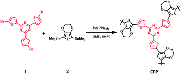
Sodium ion batteries are attractive due to the abundance of sodium in the earth's crust.1,2 Sodium ion is larger than the lithium ion; hence, transforming the understanding emanated from lithium ion battery research into sodium ion battery investigations is not straightforward.3,4 However, a successful lithium battery electrode exhibited impressive performance while it was being used as an electrode in a sodium ion battery.5–7 This was an exception. Often, natural resources are carbonized to prepare sodium ion battery electrodes.8–11 These electrodes exhibit specific capacities ranging between 180 mA h g−1 to 355 mA h g−1. Conjugated and vinyl polymers can be carbonized to prepare sodium ion battery electrodes.12–14 One common feature of these electrodes is heteroatom doping. Sulfur and nitrogen atoms increase the spacing between the graphene layers, which improves sodium ion insertion and de-insertion.15–20 Recently, conjugated porous polymers (CPPs) have become a preferred precursor for the synthesis of energy storage materials.21–30 We hypothesized that a CPP comprising of sulfur, nitrogen and oxygen would be a useful precursor for preparing carbon-based electrodes with increased interlayer spacings. The removal of oxygen during carbonization was easier than the removal of other heteroatoms during high temperature annealing. However, the removal of heteroatoms varies as a function of temperature.31 Thus, at the optimum temperature, the interlayer spacing, as well as the presence of heteroatoms, can become ideal for synthesis of a sodium ion battery electrode. To test this hypothesis, we synthesized a CPP (Scheme 1) using Stille coupling. Then, the CPP was carbonized at three temperatures (800, 1000 and 1200 °C) to identify suitable synthesis conditions for a sodium ion battery electrode. One of the carbonized materials showed an impressive specific capacity of 250 mA h g−1, while the charge discharge experiment was carried out at 50 mA g−1.
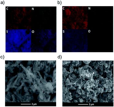
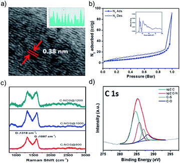
The CPP synthesis was carried out by reacting 1 (ref. 26) with trimethyltin-substituted 3,4-ethylenedioxythiophene (2). Thermogravimetric analysis was carried out to study the thermal profile of the CPP. About 10% weight loss was observed at 370 °C. Upon reaching 800 °C, 20% of the CPP remained in the pan, indicating the formation of carbon. The electrode materials were prepared by heating the CPP at 800, 1000 and 1200 °C, and the resulting products were named C-NOS@800, C-NOS@1000 and C-NOS@1200, respectively. Collectively, they will be referred to as C-NOS. Elemental mapping using scanning electron microscopy (SEM) is a useful technique to identify the presence of elements such as C, S, N and O. The CPP was subjected to elemental mapping, which revealed the uniform distribution of all these elements (Fig. 1a). Then, C-NOS@1000 was subjected to elemental mapping. A marked difference in the presence of oxygen was observed (Fig. 1b). This indicated the removal of oxygen from the CPP during the conversion to carbon. A small variation in the oxygen distribution was observed upon heating the CPP at 1200 °C (Fig. S7, ESI†). The elemental map did not show significant variations in the presence and distribution of C, N and S for CPP, C-NOS@1000 or C-NOS@1200. SEM was used to study the morphology of CPP and C-NOS. A nanofibrillar morphology was found for CPP (Fig. 1c). The fibril diameter was found to be 0.4 μm. Upon thermal treatment, the fibrils broke into smaller pieces. In some areas, an uneven film was visible (Fig. 1d). The thermal treatment likely fused the broken fibrils, which resulted in the change of morphology. TEM was used to gain detailed information on the nanoscopic features of CPP as well as C-NOS. The high resolution TEM (HRTEM) image of CPP did not show any layered features (Fig. S8, ESI†). On the other hand, HRTEM images of C-NOS@800 showed a layered structure, and the inter layer distance was found to be 0.42 nm. The high interlayer spacing was possibly due to the non-removal of heteroatoms. The interlayer spacing decreased to 0.38 nm upon heating the CPP at 1000 °C (C-NOS@1000) (Fig. 2a). The interlayer spacing was found to decrease to 0.37 nm for C-NOS@1200. The decreases in interlayer spacing upon heating CPP at 1000 and 1200 °C were due to the loss of heteroatoms.
 | ||
| Fig. 1 Elemental mapping image showing the distribution of elements in CPP (a) and C-NOS@1000 (b). SEM image showing the morphology of CPP (c) and C-NOS@1000 (d). | ||
The surface area and pore width of C-NOS were calculated by BET method (Fig. 2b). The surface area was found to be 18 m2 g−1, 35 m2 g−1 and 60 m2 g−1 for CPP, C-NOS@1000 and C-NOS@1200, respectively. The increase in area was possibly due to the removal of oxygen, which resulted in an increased number of pores in C-NOS. The Raman spectra of C-NOS exhibited two peaks indicating the presence of D and G-bands. The G-band was at 1587 cm−1 and the D-band was at 1318 cm−1. The ratio of the intensity of G-band to D-band is an indication of the presence of graphitic carbon. The ratio (IG/ID) increased from 0.87 for C-NOS@800 to 0.9 for C-NOS@1000 and increased further to 0.97 for C-NOS@1200 (Fig. 2c). Thus, thermal treatment helps to increase graphitic carbon content among the C-NOS series. The powder XRD pattern of CPP and C-NOS were recorded to study the crystalline nature, if any. A broad peak was observed for the CPP and C-NOS, which sharpened for C-NOS@1000. However, the peak was not sharp enough to assign any planes. Indeed, this behavior has been observed for several CPPs and its carbonized samples.23 XPS spectra were employed to understand the hybridization in CPP and C-NOS. In the case of CPP, the C 1s peaks at 284.8 and 285.7 eV were due to sp2 C and C–N bonds, respectively (Fig. 2d). The C 1s peaks at 286.8 and 288 eV were assigned to C–S and C–O, respectively. The N 1s peak at 398.7 eV corresponded to the pyridinic C–N bond. The S 2p3/2 and S 2p1/2 peaks appear at 164.3 and 165 eV, respectively. The same peaks appear for C-NOS as well. However, an intense N 1s peak at 401.1 eV indicated improved formation of graphitic carbon. The percentage of elements present in CPP and C-NOS is provided in Table S1 (ESI†).
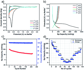
After the characterization of CPP and C-NOS, we proceeded to fabricate sodium ion batteries. The electrodes comprised active material (80%), binder (5%) and carbon black (15%). The counter electrode was sodium metal and the electrolyte was 1 M NaPF6 dissolved in ethylene carbonate and diethyl carbonate. Cyclic voltammetry measurements of the battery were recorded using C-NOS as the working electrode. The potential was swept between 3 V and 0.001 V vs. Na/Na+. A sharp peak was observed at 0.3 V vs. Na/Na+, which diminished in the subsequent cycles (Fig. 3a). The sharp peak in the first cycle was attributed to solid electrolyte interface (SEI) layer formation. The charge–discharge characteristics of the battery were evaluated at various current densities ranging between 50 mA g−1 to 10 A g−1. In all these experiments, the specific capacity in the first cycle was very high. For example, a specific capacity of 900 mA h g−1 was observed while discharging a battery comprising of C-NOS@1000 at 50 mA g−1 (Fig. 3b). This high specific capacity was due to SEI layer formation. For the same battery, the specific capacity at the second cycle was found to be 250 mA h g−1. It is interesting to note that the coulombic efficiency was found to be 100%. In fact, the coulombic efficiency remained at 100% even after 200 cycles of charge–discharge measurements (Fig. 3c). The charge discharge experiments were carried out at various rates. For C-NOS@1000, the specific capacity decreased from 250 mA h g−1 to 5 mA h g−1. The lowest specific capacity was observed at 5 A g−1 and the highest was observed at 50 mA g−1 (Fig. 3d). The performance of the battery comprising of C-NOS@1200 was lower than that of batteries with C-NOS@1000. The highest specific capacity for the C-NOS@1200 containing battery was found to be 126 mA h g−1, while the battery was discharged at 100 mA g−1. For this battery, the lowest specific capacity was observed, while the discharge experiment was carried out at 1 A g−1. The performance of C-NOS@800 was not impressive because the recharge ability of the battery was poor. The charge–discharge experiment could not be carried out beyond 300 mA g−1. The specific capacity was 6 mA h g−1 while discharging at 300 mA g−1, which was much lower compared to C-NOS@1000 and C-NOS@1200. In fact, C-NOS@1000 exhibited a specific capacity of 116 mA h g−1 while discharging at the same rate. From these experiments, it is clear that C-NOS@1000 exhibited better performance than the other two systems because (i) the interlayer spacing was 0.38 nm and (ii) due to the presence of increased quantities of graphitic carbon.
In summary, we have designed and synthesized a CPP comprising of three heteroatoms: S, O and N. The sulfur and nitrogen facilitate the formation of graphene with the desired interlayer spacing for a sodium ion battery. The removal of oxygen from the CPP during the carbonization step helps the formation of material suitable for the insertion and desertion of large anions, such as sodium. The interlayer spacing of 0.38 nm was found for C-NOS@1000, and this sodium ion battery exhibited a specific capacity of 250 mA h g−1. The polymer design involved the use of heteroatoms to achieve the desired interlayer spacing. This design strategy opens up the possibility of using other molecules to prepare materials suitable for sodium ion batteries.
Acknowledgements
We thank CSIR for financial support (TAPSUN NWP 54). MEB thank Council of Scientific and Industrial Research for scholarship.Notes and references
- Y. Wen, K. He, Y. J. Zhu, F. D. Han, Y. H. Xu, I. Matsuda, Y. Ishii, J. Cumings and C. S. Wang, Nat. Commun., 2014, 5, 4033 CAS.
- D. Kundu, E. Talaie, V. Duffort and L. F. Nazar, Angew. Chem., Int. Ed., 2015, 54, 3431 CrossRef CAS PubMed.
- L. P. Wang, L. H. Yu, X. Wang, M. Srinivasan and Z. C. J. Xu, J. Mater. Chem. A, 2015, 3, 9353 CAS.
- H. Kim, J. Hong, K. Y. Park, H. Kim, S. W. Kim and K. Kang, Chem. Rev., 2014, 114, 11788 CrossRef CAS PubMed.
- E. M. Lotfabad, J. Ding, K. Cui, A. Kohandehghan, W. P. Kalisvaart, M. Hazelton and D. Mitlin, ACS Nano, 2014, 8, 7115 CrossRef CAS PubMed.
- H. G. Wang, S. Yuan, D. L. Ma, X. B. Zhang and J. M. Yan, Energy Environ. Sci., 2015, 8, 1660 CAS.
- K. Zhang, X. Li, J. Liang, Y. Zhu, L. Hu, Q. Cheng, C. Guo, N. Lin and Y. Qian, Electrochim. Acta, 2015, 155, 174 CrossRef CAS.
- K.-L. Hong, L. Qie, R. Zeng, Z.-Q. Yi, W. Zhang, D. Wang, W. Yin, C. Wu, Q.-J. Fan, W.-X. Zhang and Y.-H. Huang, J. Mater. Chem. A, 2014, 2, 12733 CAS.
- J. Ding, H. Wang, Z. Li, A. Kohandehghan, K. Cui, Z. Xu, B. Zahiri, X. Tan, E. M. Lotfabad, B. C. Olsen and D. Mitlin, ACS Nano, 2013, 7, 11004 CrossRef CAS PubMed.
- F. Shen, H. Zhu, W. Luo, J. Wan, L. Zhou, J. Dai, B. Zhao, X. Han, K. Fu and L. Hu, ACS Appl. Mater. Interfaces, 2015, 7, 23291 CAS.
- Y. M. Li, Y. S. Hu, H. Li, L. Q. Chen and X. J. Huang, J. Mater. Chem. A, 2016, 4, 96 CAS.
- H. G. Wang, Z. Wu, F. L. Meng, D. L. Ma, X. L. Huang, L. M. Wang and X. B. Zhang, ChemSusChem, 2013, 6, 56 CrossRef PubMed.
- Y. L. Cao, L. F. Xiao, M. L. Sushko, W. Wang, B. Schwenzer, J. Xiao, Z. M. Nie, L. V. Saraf, Z. G. Yang and J. Liu, Nano Lett., 2012, 12, 3783 CrossRef CAS PubMed.
- Y. Bai, Z. Wang, C. Wu, R. Xu, F. Wu, Y. Liu, H. Li, Y. Li, J. Lu and K. Amine, ACS Appl. Mater. Interfaces, 2015, 7, 5598 CAS.
- J. Xu, M. Wang, N. Wickramaratne, M. Jaroniec, S. Dou and L. Dai, Adv. Mater., 2015, 27, 2042 CrossRef CAS PubMed.
- L. Fu, K. Tang, K. Song, P. A. Van Aken, Y. Yu and J. Maier, Nanoscale, 2014, 6, 1384 RSC.
- W. Li, M. Zhou, H. Li, K. Wang, S. Cheng and K. Jiang, Energy Environ. Sci., 2015, 8, 2916 CAS.
- L. Qie, W. Chen, X. Xiong, C. Hu, F. Zou, P. Hu and Y. Huang, Adv. Sci., 2015, 1500195 Search PubMed.
- D. D. Li, L. Zhang, H. B. Chen, L. X. Ding, S. Q. Wang and H. H. Wang, Chem. Commun., 2015, 51, 16045 RSC.
- D. Xu, C. Chen, J. Xie, B. Zhang, L. Miao, J. Cai, Y. Huang and L. Zhang, Adv. Energy Mater., 2016, 6, 1501929 CrossRef.
- Z. Xiang, D. Cao, L. Huang, J. Shui, M. Wang and L. Dai, Adv. Mater., 2014, 26, 3315 CrossRef CAS PubMed.
- Y. Xu, S. Jin, H. Xu, A. Nagai and D. Jiang, Chem. Soc. Rev., 2013, 42, 8012 RSC.
- Y. Kou, Y. H. Xu, Z. Q. Guo and D. Jiang, Angew. Chem., Int. Ed., 2011, 50, 8753 CrossRef CAS PubMed.
- A. L. Reddy, S. R. Gowda, M. M. Shaijumon and P. M. Ajayan, Adv. Mater., 2012, 24, 5045 CrossRef CAS PubMed.
- R. S. Sprick, J.-X. Jiang, B. Bonillo, S. Ren, T. Ratvijitvech, P. Guiglion, M. A. Zwijnenburg, D. J. Adams and A. I. Cooper, J. Am. Chem. Soc., 2015, 137, 3265 CrossRef CAS PubMed.
- M. E. Bhosale, R. Illathvalappil, S. Kurungot and K. Krishnamoorthy, Chem. Commun., 2016, 52, 316 RSC.
- Y. Shao, M. F. El-Kady, L. J. Wang, Q. Zhang, Y. Li, H. Wang, M. F. Mousavi and R. B. Kaner, Chem. Soc. Rev., 2015, 44, 3639 RSC.
- X. Feng, Y. Liang, L. Zhi, A. Thomas, D. Wu, I. Lieberwirth, U. Kolb and K. Mullen, Adv. Funct. Mater., 2009, 19, 2125 CrossRef CAS.
- Z. Xiang, Y. Xue, D. Cao, L. Huang, J. Chen and L. Dai, Angew. Chem., Int. Ed., 2014, 53, 2433 CrossRef CAS PubMed.
- J. W. To, Z. Chen, H. Yao, J. He, K. Kim, H. H. Chou, L. Pan, J. Wilcox, Y. Cui and Z. Bao, ACS Cent. Sci., 2015, 1, 68 CrossRef CAS PubMed.
- Z. Wang, X. Xiong, L. Qie and Y. Huang, Electrochim. Acta, 2013, 106, 320 CrossRef CAS.
Footnote |
| † Electronic supplementary information (ESI) available: Experimental procedures, synthetic schemes, NMR, TGA, BET, XRD, XPS, TEM, are available. See DOI: 10.1039/c6ra27662h |
| This journal is © The Royal Society of Chemistry 2017 |


