
 Open Access Article
 This Open Access Article is licensed under a Creative Commons Attribution-Non Commercial 3.0 Unported Licence
Design of gold nanoparticles-decorated SiO2@TiO2 core/shell nanostructures for visible light-activated photocatalysis
Ryeri Leea,
Yogeenth Kumaresana,
Sei Young Yoonb,
Soong Ho Umc,
Il Keun Kwon *d and
Gun Young Jung*a
*d and
Gun Young Jung*a
aSchool of Materials Science and Engineering, Gwangju Institute of Science and Technology (GIST), Gwangju 61005, Republic of Korea. E-mail: gyjung@gist.ac.kr
bDepartment of Cosmetic Science, Daejeon Health Institute of Technology, Daejeon, 34504, Republic of Korea
cDepartment of Chemical Engineering, SKKU Advanced Institute of Nanotechnology (SAINT), Sungkyunkwan University, Suwon, 16419, Republic of Korea
dDepartment of Maxillofacial Biomedical Engineering, Institute of Oral Biology, School of Dentistry, Kyung Hee University, Seoul, 02447, Republic of Korea. E-mail: kwoni@khu.ac.kr
First published on 23rd January 2017
Abstract
In this study, we designed core/shell nanostructures (CSNs) of silicon dioxide (SiO2)/titanium dioxide (TiO2), which were decorated with gold (Au) nanoparticles (NPs), to activate the visible light-driven photocatalytic reaction that is not feasible with only the SiO2@TiO2 CSN because there is no absorption in the visible wavelengths. The CSNs were simply synthesized by hydrothermal method. In the core/shell structure, TiO2 covered the SiO2 core surface, which acts as a template. The attachment of additional Au NPs inside or outside the core/shell led to absorbance in visible wavelengths of light from the Sun, from which most radiation comes with a spectrum peak at yellow wavelength, owing to the localized surface plasmon resonance (LSPR) peak at approximately 550 nm. The SiO2@Au@TiO2@Au CSN (0.01 g) decomposed 1% of methyl orange (MO) solution in 15 mL deionized water in 1 h under the visible light. The visible light-driven photocatalytic reaction was ascribed to the LSPR around the Au NPs that were deposited inner or outer the mesoporous TiO2 shell.
1 Introduction
TiO2 is a well-known mineral with many attractive characteristics such as nontoxicity, chemical stability to acidic and/or basic conditions, long-term stability, and good oxidizing ability.1,2 Thus, many researchers have studied the usage of TiO2 to extend its applications in different fields such as UV blocking pigments, self-cleaning materials, dye-sensitized solar cells, humidity sensors, lithium-ion storage, and photocatalysts.3–9 TiO2 NPs have been used as an effective photocatalyst to solve environmental problems by decomposing organic pollutants in water into CO2 and H2O.9,10 When the sun light illuminates TiO2 in water, TiO2 oxidizes H2O molecules into hydroxyl radicals (˙OH), which can decompose the organic pollutants in water.10However, TiO2 has a limited photocatalytic activity only in the UV-light region (<400 nm) because of its wide bandgap (∼3.2 eV [388 nm] for the anatase crystalline phase) and fast recombination of photo-generated electrons with holes.1 UV light comprises a small fraction (approximately 4%) of the sun-light spectrum, whereas visible light comprises 44.4% intensity of the sun-light. To use the abundant visible light as an energy source for photocatalytic activity, many different approaches have been made to narrow the TiO2 bandgap for absorbing the light at visible wavelengths by doping the TiO2 with transition metal dopants (tungsten, copper and iron)11–13 and anionic nonmetal dopants (nitrogen and iodine).14,15 However, these doping methods have many drawbacks such as a low doping concentration, reduced electron–hole lifetime, and low corrosion resistance.16,17 Another method to generate the visible light responsive TiO2 was achieved by using noble metals, e.g., gold (Au), silver (Ag), and platinum (Pt).18–20 Noble metals are successfully used because of their chemical stability and visible-light absorption due to the localized surface plasmon resonance (LSPR),21,22 in which the conducting electrons on the noble metal surface undergo a collective oscillation induced by the light at a certain wavelength. Thus, at a plasmon resonant frequency the light absorption of noble metal NPs can be made. Because of this unique effect, noble metals assist the photocatalytic activity of semiconductors by absorbing the light at visible wavelengths and injecting the photo-generated electrons from the noble metal into the conduction band of the semiconductor.
Guo et al. reported that the Au NPs deposited at both sides of 5 nm thick TiO2 sheet showed an enhanced near-field amplitude of localized surface plasmon resonance between the nearly touching Au NPs with a spacing of 5 nm, which could boost the photocatalytic activity of TiO2 sheet.23 Recently, Kim et al. synthesized Au NPs-decorated SiO2@amorphous TiO2 core/shell structures and incorporated those into the photoanodes in dye-sensitized solar cells. Because of the plasmonic effect at the Au NPs, short-circuit current increased and power conversion efficiency was accordingly enhanced by 14%.24 In addition, Hong et al. introduced 60 nm-sized Au NPs-attached TiO2 nanofibers into an electron-transporting layer in perovskite solar cells and improved the conversion efficiency by 15% because of the LSPR effect.25
Until now, the location of Au NPs (inner or outer of the TiO2 shell) and the number of Au NP layers within the CSNs, which can play a significant role in enhancing the optical properties in the visible-light region, have not been deeply studied. In this study, we designed various visible light-driven core/shell nanostructured (CSN) photocatalysts, in which the SiO2 core was decorated with various arrangements of both Au NPs layer and TiO2 shell. To investigate the LSPR effect of various CSNs on the photocatalytic activity, their optical properties and methyl orange (MO) decomposition abilities were compared among them, and with those of the commercially available mixed-phase of anatase and rutile TiO2 (Degussa, P25).
2 Experimental
2.1 Materials and reagents
All chemical reagents were of analytical grade and used without further purification: ethanol (CH3CH2OH, anhydrous, Samchun Chem.), tetraethyl orthosilicate (TEOS, Si(OC2H5)4, 99%, Sigma-Aldrich Co., Ltd), ammonia hydroxide solution (NH4OH, 28–30%, Sigma-Aldrich Co., Ltd), titanium butoxide (TBT, Ti(OCH2CH2CH2CH3)4, 97%, Sigma-Aldrich Co., Ltd), (3-aminopropyl)trimethoxysilane (APTMS, H2N(CH2)3Si(OCH3)3, 97%, Sigma-Aldrich Co., Ltd), gold(III) chloride hydrate (HAuCl4·xH2O, 99.999%, Sigma-Aldrich Co., Ltd), sodium citrate tribasic dehydrate (HOC(COONa)(CH2COONa)2·2H2O, 99.9%, Sigma-Aldrich Co., Ltd), and P25. Commercial MO (C14H14N3NaO3S, 0.1%, Sigma-Aldrich Co., Ltd) was used as a target dye. All aqueous solutions were prepared with deionized (DI) water, filtered using a Milli-Q plus system (ρ ≥ 18 MΩ cm).2.2 Synthesis of SiO2@Au CSN
SiO2 spheres were produced using the well-known Stöber method.26 0.3 mM TEOS in 80 mL ethanol as a SiO2 precursor was mixed with 3 mL ammonia hydroxide and 5 mL DI water, and stirred at room temperature for 12 h. Amine functionalization at the SiO2 sphere surface is necessary for the attachment of Au NPs by electrostatic interaction. 1 mL APTMS was slowly added into the prepared SiO2 spheres-dispersed DI solution under mild stirring (400 rpm), and the solution was placed in a conventional oven at 70 °C for 4 h to initiate the amine functionalization at the Au NP surface. After the reaction, the amine functionalized SiO2 spheres were thoroughly washed three times using a centrifuge (5000 rpm for 30 min). The collected amine-functionalized SiO2 spheres were mixed with the Au NP solution, which was prepared using the Turkevich method;27 0.5 mM gold(III) chloride hydrate was added into 30 mL boiling DI water (hot-plate temperature: 300 °C) with vigorous stirring (800 rpm). 100 mM sodium citrate DI solution was added into the boiling Au precursor solution for 15 min until the solution changed from colourless to red violet.2.3 Synthesis of SiO2@Au@TiO2@Au CSN
To obtain the SiO2@Au@TiO2 CSN, 15 mM TBT in ethanol was injected using a syringe pump into 50 mL ethanol solution having the dispersed SiO2@Au CSN under mild stirring (300 rpm). After adding 4 mL DI water, the solution was transferred to a Teflon autoclave and placed in an oven at 130 °C for 12 h. After cooling to room temperate, the precipitate was washed with ethanol 3 times using a centrifuge. The washed precipitate of SiO2@Au@TiO2 CSN was dispersed in ethanol and mixed with APTMS for further amine functionalization on the TiO2 shell surface as previously mentioned. After the amine functionalization, the Au NP solution was added into the SiO2@Au@TiO2 CSN-dispersed DI solution for the final Au NP attachment to the outer shell of TiO2.2.4 Photocatalytic experiments
Three different CSNs (SiO2@Au@TiO2, SiO2@TiO2@Au, and SiO2@Au@TiO2@Au) were prepared to measure the photocatalytic activity, and to compare their activity with that of the widely used P25 (TiO2, Degussa). The photocatalytic activity was measured in ambient atmosphere at room temperature by degrading the methyl orange (MO) solution with illumination with an AM 1.5 simulated sunlight source (SANNEI solar simulator, Class A). The UV light (λ < 400 nm) was cut off using a UV shield film (SK-2, Sunnano) to observe the photocatalytic activity under only visible light at a power density of 80 ± 2.5 mW cm−2. Each CSN powder (0.01 g) was added into 20 mL DI water with 1 vol% of MO. The CSN suspensions were vigorously stirred in the dark for 30 min to reach adsorption/desorption equilibrium of MO molecules on the CSN surface. At every 15 min, 1 mL suspension was sampled and filtered to measure the resident MO concentration using a UV-visible spectrometer (AvaSpec-ULS2048L-USB2 Spectrometer, Jinyoung tech Inc.).3 Result and discussion
3.1 Structure observation
We synthesized the SiO2@Au@TiO2@Au CSN by coating the Au NPs and TiO2 on the SiO2 core in sequence as depicted in Fig. 1. The amine (NH3+) functionalization facilitated the attachment of Au NPs onto the both SiO2 core and TiO2 shell surface. Therefore, uniform amine functionalization was the most important step to achieve the dense coverage of Au NPs. To obtain the uniform amine functionalization, dispersion of the SiO2 spheres in ethanol at a low concentration was necessary. The Au NPs prepared using the Turkevich method were surrounded with negatively charged citrate ions (C3H5O(COO)33−), which improved the dispersion and stabilization of Au NPs in the solution owing to the electrostatic repulsion between them. Meanwhile, those negatively charged citrate ions electrostatically attracted the positively charged NH3+ functionalized SiO2 spheres to form the Au NPs coating. Scanning electron microscope (FE-SEM, JEOL 2010F) images of the SiO2, SiO2@Au, SiO2@Au@TiO2, and SiO2@Au@TiO2@Au CSNs are shown in Fig. 2a–d. Fig. 2a shows the 200 nm-sized SiO2 core with a smooth surface. In contrast, the SiO2@Au has a rough surface with the Au NPs (Fig. 2b). The high-resolution image of it (inset of Fig. 2b) shows the average size of Au NPs of 15 nm. Fig. 2c shows two SiO2@Au@TiO2 CSNs after complete coverage with the TiO2 shell. In this case, the Au NPs are invisible after coating the 30 nm-thick TiO2 shell, which was composed of a few nanometer-sized TiO2 NPs with a relatively smooth SiO2@Au@TiO2 CSN surface.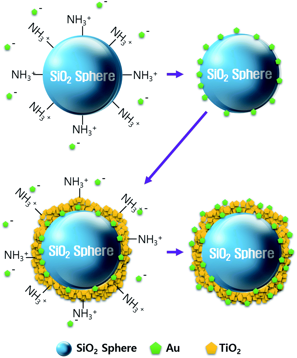 | ||
| Fig. 1 Schematic representation of the SiO2@Au@TiO2@Au CSN synthesis. | ||
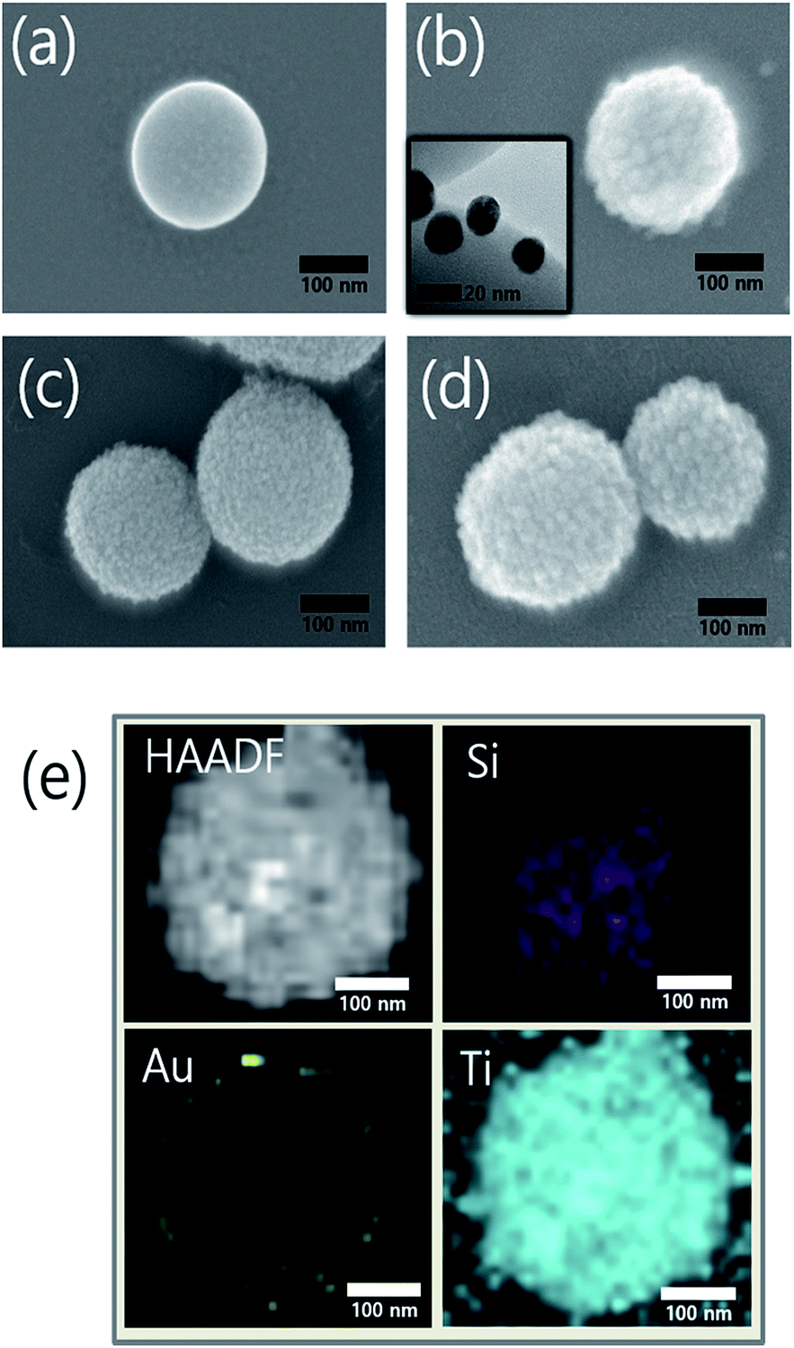 | ||
| Fig. 2 SEM images of (a) bare SiO2, (b) SiO2@Au, (c) SiO2@Au@TiO2, and (d) SiO2@Au@TiO2@Au. (e) HAADF-STEM image and the corresponding EDS element mapping images of silicon (Si, purple), gold (Au, yellow) and titanium (Ti, skyblue) for the SiO2@Au@TiO2 CSN. The inset of (c) is the high-resolution TEM image of Au NPs on the SiO2 sphere surface. | ||
The TiO2 shell was formed by two different mechanisms above 130 °C: intermediate titanium hydroxide (Ti(OH)4) was formed in the hydrolysis reaction (i) and converted into TiO2 by condensation reaction (ii) or TBT decomposition by reaction with the intermediate Ti(OH)4 into TiO2 and by-product of butanol (iii):28
| Ti(OCH2CH2CH2CH3)4 + 4H2O → Ti(OH)4 + 4CH3CH2CH2CH2OH | (i) |
| Ti(OH)4 → TiO2 + 2H2O | (ii) |
| Ti(OCH2CH2CH2CH3)4 + Ti(OH)4 → 2TiO2 + 4CH3CH2CH2CH2OH | (iii) |
Fig. 2d shows the Au NPs that were coated onto the entire surface of a SiO2@Au@TiO2 CSN. For the Au NP attachment, the NH3+ functionalization treatment was also performed to the TiO2 shell. Fig. 2e shows a high-angle annular dark-field (HAADF) image of the SiO2@Au@TiO2 CSN and the corresponding elemental mappings of Si, Au and Ti. It is shown that the Au NPs coated the SiO2 core surface and were then thoroughly covered by the TiO2 shell.
Fig. 3 shows the X-ray diffraction (XRD) patterns from three different samples using Cu K-alpha radiation (40 kV, 100 mA, Rigaku D/max-2400). The broad XRD pattern between 20° and 30° comes from the amorphous SiO2 sphere (JCPDS 29-0085, ICSD data).29 The SiO2@Au powder revealed two sharp peaks at 38.18° and 44.38°, which correspond to the Au cubic crystal (111) and (200) peaks, respectively (JCPDS 65-2870).30 The diffraction peaks of the anatase TiO2 crystal planes of (101), (200), (105) and (211) were observed from the SiO2@Au@TiO2@Au powder (JCPDS-521-1272, ICSD data),31 which were not shown in the SiO2@Au diffraction pattern. These peaks indicate that the synthesized TiO2 shell had anatase crystallinity, which has been reported to show the best photocatalytic activity among various TiO2 crystallinities (rutile, brookite, and anatase).32 Only Au, TiO2, and SiO2 diffraction peaks were observed, demonstrating that no impurities remained in the synthesized CSNs.
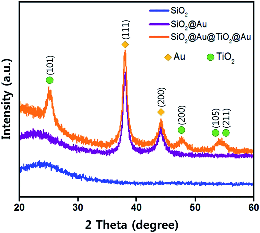 | ||
| Fig. 3 X-ray diffraction patterns of as-prepared SiO2, SiO2@Au and SiO2@Au@TiO2@Au CSNs. | ||
3.2 Optical characteristics of core/shell materials
The UV-Vis. absorption spectra of ethanol solutions (4 mL) that contained 0.001 g of each synthesized SiO2@TiO2, SiO2@Au@TiO2, SiO2@TiO2@Au, and SiO2@Au@TiO2@Au CSN are shown in Fig. 4. The four SiO2@TiO2-based CSNs have an absorption in the UV range and absorption edge at 313 nm. After the Au NPs attachment, the SiO2@TiO2@Au sample had an absorption peak at 550 nm, which is ascribed to the collective oscillation of metal conduction electrons driven by a specific wavelength (LSPR). This peak was red-shifted to 572 nm in the SiO2@Au@TiO2 sample. Because the LSPR is sensitive to the complex dielectric environments,33 the number of neighboring Au NPs,34 and interparticle spacing of Au NPs,35 the LSPR peak from the Au NPs can shift depending on their arrangement and location. It is reported that when the interparticle spacing becomes smaller lithographically, the absorption peak from the Au NPs is broadened and shifted to the red.35 In our case, when the Au NPs were located at both the inner and outer TiO2 shell, the LSPR absorption band was interestingly broadened through visible wavelengths and even extended to the infrared region, which could be caused by the plasmonic coupling between the two Au NPs layers with a gap of 30 nm-thick TiO2 dielectric shell. We made three identical sample sets, showing the similar absorption spectra tendency among the samples.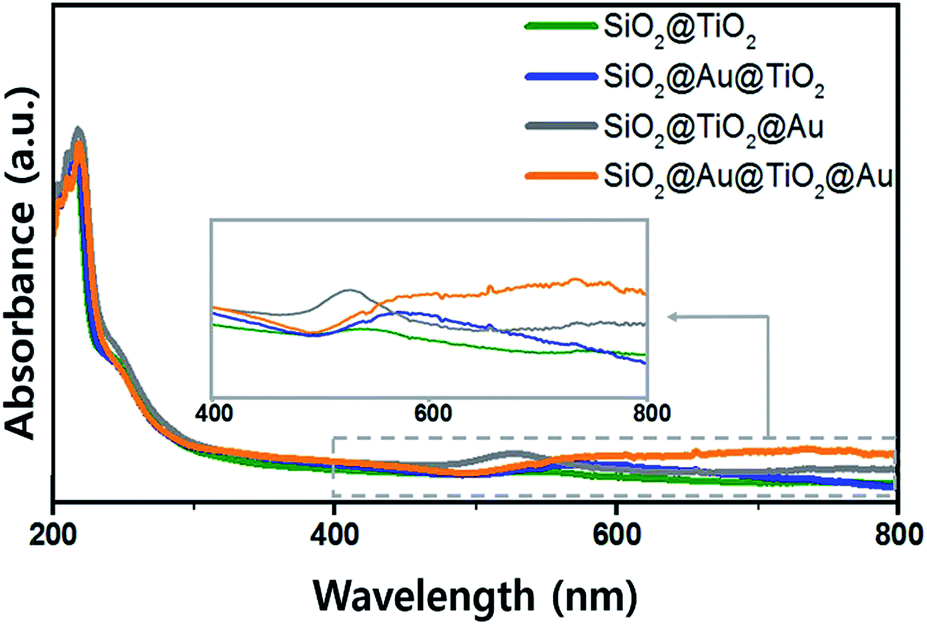 | ||
| Fig. 4 UV-visible absorption spectra of various SiO2@TiO2 CSNs. | ||
3.3 Photocatalytic activity of core/shell materials under visible light
In order to test the visible light-driven photocatalytic ability of the synthesized CSNs, the MO solution was photocatalytically degraded by illuminating the MO solution containing the dispersed CSN powders with visible light. MO is widely used by chemists to indicate the titration of acid by observing its colour change below pH 3.1. Because of its mutagenic properties and acidity (pH 3.47), direct contact should be avoided for health concern.36 Therefore, the decomposition of MO is required for health concern and environment safety.At first, the MO solution without any photocatalyst was irradiated to check the photolysis of MO itself under visible wavelengths with a simulated sunlight source at an intensity of 80 ± 2.5 mW cm−2. But, no photolytic reaction of the only MO solution to the visible light was observed. Fig. 5a–d compare the absorbance variations of MO after photodegradation under visible light. Compared to the commercially available P25, all Au-decorated CSN samples obviously showed enhanced visible light-driven photocatalytic activities. The intensity of MO absorption peak (λ = 485 nm) decreased with the irradiation time. Meanwhile, in the case of P25 sample, the MO was not decomposed at all with the irradiation time because the visible light cannot provide sufficient energy to excite the electrons over its large bandgap to generate electron–hole pairs. However, in the case of Au NPs-coated CSN samples (SiO2@Au@TiO2, SiO2@TiO2@Au, and SiO2@Au@TiO2@Au), electrons are generated under visible light because of the LSPR at the Au NPs and transferred to the conduction band of TiO2 within femto seconds as shown in Fig. 6.37 The transferred electrons can generate hydroxyl radicals (˙OH) at the TiO2/water interface,38,39 which eventually decompose the MO in the solution into non-hazardous by-products. Meanwhile, after electrons' transfer to the TiO2, the holes remained in the Au NPs oxidized the interfacing water to produce the hydroxyl radicals, which additionally decomposed the MO molecules.40–44
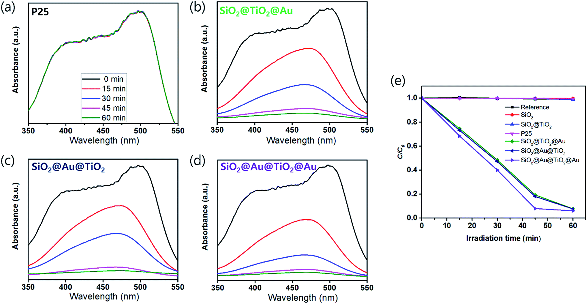 | ||
| Fig. 5 UV-vis absorption spectra showing the degradation of MO solution with varying irradiation time under visible light by (a) P25, (b) SiO2@TiO2@Au, (c) SiO2@Au@TiO2, and (d) SiO2@Au@TiO2@Au. (e) A comparison of the photocatalytic activity of reference, SiO2, SiO2@TiO2, the Au NPs-decorated CSN photocatalysts and P25 under the visible light. | ||
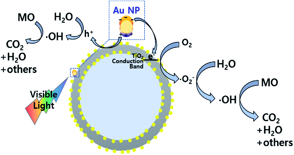 | ||
| Fig. 6 Photocatalytic mechanism of the Au NPs-decorated SiO2@Au@TiO2 CSN under the visible light irradiation. | ||
The SiO2@Au@TiO2@Au sample had the best photocatalytic performance among the CSN samples. In this case, both sides of the TiO2 shell were coated by the Au NPs, which generated more visible light-driven electrons and consequently hydroxyl radicals at the TiO2/water interface.
Fig. 5e shows the degradation efficiency of the photocatalyst by measuring the change in MO concentration (C/C0) with irradiation time (C0 is the initial concentration and C is the MO concentration after a certain irradiation time). The degradation efficiency is defined as follows:
| Degradation (%) = (1 − C/C0) × 100% |
There was no photocatalytic activity with the SiO2, SiO2@TiO2 and P25 samples, the Au-decorated CSNs decomposed nearly the entire MO quantity in an hour under visible light, illustrating that the visible light was absorbed at the Au NPs due to LSPR. The photodegradation rate is expressed as follows:45
| ln(C/C0) = −kt |
3.4 Porosity study of SiO2@TiO2 core/shell
To evidence the infiltration of MO solution to the inner Au NPs layer, the porosity of TiO2 shell was checked by the Brunauer–Emmett–Teller (BET) and Barrett–Joyner–Halenda (BJH) methods. A TEM image of Fig. 7a depicts the SiO2 spheres coated with the mesoporous TiO2 shell, which is composed of a few nm-sized nanoparticles as shown in inset figure. Adsorption/desorption of nitrogen (N2) analysis was performed with a ASAP 2020 (Micromeritics, USA) at 77.30 K. Prior to performing the BET experiment, the SiO2 and SiO2@TiO2 powder samples were degassed at 150 °C. In Fig. 7b, the N2 gas adsorption/desorption isotherm curves for SiO2 and SiO2@TiO2 samples follow the type (IV) isotherm curve with a hysteresis loop, representing the mesoporosity of both samples.46 The BET surface area of SiO2@TiO2 and SiO2 were 12.83 m2 g−1 and 134.88 m2 g−1, respectively. Hence, the SiO2@TiO2 powder absorbed much larger amount of N2 gas than that of the SiO2 powder owing to the mesoporous TiO2 shell. In comparison, the previously synthesized SiO2@TiO2 core/shell had a surface area of only 14.6 m2 g−1.47 Owing to the higher TiO2 shell mesoporosity and closely packed Au NPs of our core/shell structure, it could show a better photocatalytic activity to decompose more pollutants.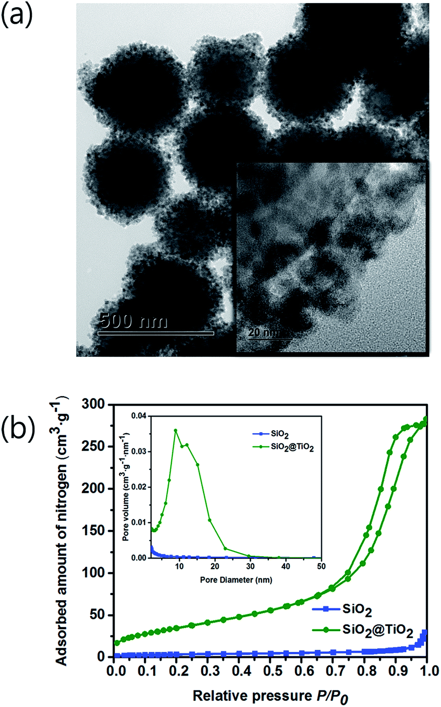 | ||
| Fig. 7 (a) TEM image of SiO2@TiO2. Inset is the high-resolution TEM image, showing the coverage of SiO2 core surface with the TiO2 NPs. (b) N2 adsorption/desorption isotherms of SiO2 and SiO2@TiO2. Inset shows the corresponding pore size distributions. | ||
The desorption isotherm was used to estimate the BJH pore-size distribution. The average pore diameters of SiO2 and SiO2@TiO2 were calculated to be 7.10 nm and 12.55 nm, respectively. Inset image in Fig. 7b shows that the TiO2 shell has a larger pore size and a pore volume than those of SiO2 core. Therefore, the MO solution could infiltrate into the inner Au NPs layer through the mesoporous TiO2 shell and be decomposed by the visible light irradiation.
4 Conclusions
SiO2@TiO2 core/shell nanostructures (CSNs) were hydrothermally synthesized to explore them as photocatalysts for the degradation of the hazardous pollutants in water. However, the visible wavelengths of the Sun cannot excite the TiO2 to generate electrons under visible light because of its large bandgap. Thus, Au NPs were attached to the inner or outer TiO2 shell by amine functionalization and electrostatic interaction. The Au NPs uniformly covered the SiO2 core and the TiO2 shell, producing the SiO2@Au@TiO2@Au CSN. The Au NPs-decorated CSNs revealed light absorption in visible wavelengths because of the localized surface plasmonic resonance at the Au NPs and even in infrared wavelengths in the case of SiO2@Au@TiO2@Au CSN. Therefore, the Au NPs-decorated CSNs decomposed MO solution under the visible light. The plasmonic effect of Au NPs led to electron generation under the visible light, which could not occur for P25. In 1 h, 0.01 g Au NPs-decorated CSNs (SiO2@Au@TiO2, SiO2@TiO2@Au, SiO2@Au@TiO2@Au) decomposed 1 vol% MO in 20 mL DI water.Acknowledgements
This work was supported by the Pioneer Research Center Program (NRF-2015M3C1A3022548) and by the “GRI (GIST Research Institute)” Project through a grant provided by GIST in 2016.Notes and references
- R. Asashi, T. Morikawa, T. Ohwaki, K. Aoki and Y. Taga, Science, 2001, 293, 269 CrossRef PubMed.
- S. M. Gupta and M. Tripathi, Chin. Sci. Bull., 2011, 56, 1639 CrossRef CAS.
- H. Yang, S. Zhu and N. Pan, J. Appl. Polym. Sci., 2004, 92, 3201 CrossRef CAS.
- H. Yaghoubi, N. Taghavinia and E. K. Alamdari, Surf. Coat. Technol., 2010, 204, 1562 CrossRef CAS.
- A. Burke, S. Ito, H. Snaith, U. Bach, J. Kwiatkowski and M. Grätzel, Nano Lett., 2008, 8, 977 CrossRef CAS PubMed.
- P.-G. Su and L. N. Huang, Sens. Actuators, B, 2007, 123, 501 CrossRef CAS.
- M.-C. Yang, Y.-Y. Lee, B. Xu, K. Powers and Y. S. Meng, J. Power Sources, 2012, 207, 166 CrossRef CAS.
- C.-C. Lin, J.-W. Liao and W.-Y. Li, Ceram. Int., 2013, 39, S733 CrossRef CAS.
- K. Nakata and A. Fujishima, J. Photochem. Photobiol., C, 2012, 13, 169 CrossRef CAS.
- J. Schneider, M. Matsuoka, M. Takeuchi, J. Zhang, Y. Horiuchi, M. Anpo and D. W. Bahnemann, Chem. Rev., 2014, 114, 9919 CrossRef CAS PubMed.
- N. Couselo, E. F. S. García, R. J. Candal and M. Jobbágy, J. Phys. Chem. C, 2008, 112, 1094 CAS.
- L. S. Yoong, F. K. Chong and B. K. Dutta, Energy, 2009, 34, 1652 CrossRef CAS.
- K. C. Christoforidis, A. Iglesiau-Juez, S. J. A. Figueroa, M. D. Michiel, M. A. Newton and M. Fernández-García, Catal. Sci. Technol., 2013, 3, 626 CAS.
- G. Yang, Z. Jiang, H. Shi, T. Xiao and Z. Yan, J. Mater. Chem., 2010, 20, 5301 RSC.
- Q. Zhang, Y. Li, E. A. Ackerman, M. Gajdardziska-Josifovska and H. Li, Appl. Catal., A, 2011, 400, 195 CrossRef CAS.
- Y. Wang, H. Cheng, Y. Hao, J. Ma, W. Li and S. Cai, Thin Solid Films, 1999, 349, 120 CrossRef CAS.
- H. Yamashita, M. Honda, M. Harada, Y. Ichihashi, M. Anpo, T. Hirao, N. Itoh and N. Iwamoto, J. Phys. Chem. B, 1998, 102, 10707 CrossRef CAS.
- A. Pandikumar, S. Murugesan and R. Ramaraj, ACS Appl. Mater. Interfaces, 2010, 2, 1912 CAS.
- D.-H. Yu, X. Yu, C. Wang, X.-C. Liu and Y. Xing, ACS Appl. Mater. Interfaces, 2012, 4, 2781 CAS.
- H. Chen, S. Chen, X. Quan, H. Yu, H. Zhao and Y. Zhang, J. Phys. Chem. C, 2008, 112, 9285 CAS.
- P. K. Jain, X. Huang, I. H. El-Sayed and M. A. El-Sayed, Acc. Chem. Res., 2008, 41, 1578 CrossRef CAS PubMed.
- T. Y. Jeon, D. J. Kim, S. G. Park, S. H. Kim and D. H. Kim, Nano Convergence, 2016, 3, 18 CrossRef.
- H. Wang, T. You, W. Shi, J. Li and L. Guo, J. Phys. Chem. C, 2012, 116, 6490 CAS.
- Y. H. Jang, Y. J. Jang, S. T. Kochuveedu, M. Byun, Z. Lin and D. H. Kim, Nanoscale, 2014, 6, 1823 RSC.
- S. S. Mali, C. S. Shim, H. Kim, P. S. Patil and C. K. Hong, Nanoscale, 2016, 8, 2664 RSC.
- W. Stöber, A. Fink and E. Bohn, J. Colloid Interface Sci., 1968, 26, 62 CrossRef.
- J. Turkevich, P. C. Stevenson and J. Hillier, Discuss. Faraday Soc., 1951, 11, 55 RSC.
- H. Li, S. G. Sunol and A. K. Sunol, Nanotechnology, 2012, 23, 294012 CrossRef CAS PubMed.
- H. Wang, M. Yu, C. K. Lin and J. Lin, J. Colloid Interface Sci., 2006, 300, 176 CrossRef CAS PubMed.
- L. Shang, F. Zhao and B. Zeng, Electroanalysis, 2013, 25, 453 CrossRef CAS.
- W. Huang, X. Tang, Y. Wang, Y. Koltypin and A. Gedanken, Chem. Commun., 2000, 48, 1415 RSC.
- J. Zhang, P. Zhou, J. Liu and J. Yu, Phys. Chem. Chem. Phys., 2014, 16, 20382 RSC.
- K. L. Kelly, E. Coronado, L. L. Zhao and G. C. Schatz, J. Phys. Chem. B, 2003, 107, 668 CrossRef CAS.
- Y. Yan, H. Shan, M. Li, S. Chen, J. Liu, Y. Cheng, C. Ye, Z. Yang, X. Lai and J. Hu, Sci. Rep., 2015, 5, 16715 CrossRef CAS PubMed.
- C. Mu, J. P. Zhang and D. Xu, Nanotechnology, 2009, 21, 015604 CrossRef PubMed.
- Y. Badr and M. A. Mahmoud, J. Phys. Chem. Solids, 2007, 68, 413 CrossRef CAS.
- A. Furube, L. Du, K. Hara, R. Katoh and M. Tachiya, J. Am. Chem. Soc., 2007, 129, 14852 CrossRef CAS PubMed.
- Q. Zhang, D. Q. Lima, I. Lee, F. Zaera, M. Chi and Y. Yin, Angew. Chem., 2011, 123, 7226 CrossRef.
- Z. Bian, J. Zhu, F. Cao, Y. Lu and H. Li, Chem. Commun., 2009, 25, 3789 RSC.
- J. Xue, S. Ma, Y. Zhou and Q. Wang, RSC Adv., 2015, 5, 88249 RSC.
- Y. Tian and T. Tatsuma, J. Am. Chem. Soc., 2005, 127, 7632 CrossRef CAS PubMed.
- S. A. Ansari, M. M. Khan, M. O. Ansari and M. H. Cho, New J. Chem., 2015, 39, 4708 RSC.
- S. T. Kochuveedu, Y. H. Jang and D. H. Kim, Chem. Soc. Rev., 2013, 42, 8467 RSC.
- C. Wang and D. Astruc, Chem. Soc. Rev., 2014, 43, 7188 RSC.
- W. Xia, H. Wang, X. Zeng, J. Han, J. Zhu, M. Zhou and S. Wu, CrystEngComm, 2014, 16, 6841 RSC.
- K. S. W. Sing, D. H. Everett, R. A. W. Haul, L. Moscou, R. A. Pierotti, J. Rouquerol and T. Siemieniewska, Pure Appl. Chem., 1985, 57, 603 CrossRef CAS.
- M. Ye, H. Zhou, T. Zhang, Y. Zhang and Y. Shao, Chem. Eng. J., 2013, 226, 209 CrossRef CAS.
| This journal is © The Royal Society of Chemistry 2017 |