 Open Access Article
Advanced anti-corrosion coatings prepared from α-zirconium phosphate/polyurethane nanocomposites†
Tsao-Cheng Huangb,
Guan-Hui Laiab,
Chen-En Lib,
Mei-Hui Tsai *ab,
Peng-Yun Wanb,
Yi-Hsiu Chungc and
Meng-Hung Lind
aPh. D. Program, Graduate Institute of Precision Manufacturing, National Chin-Yi University of Technology, 41170 Taichung, Taiwan, Republic of China. E-mail: tsaimh@ncut.edu.tw; Fax: +886-4-23926617; Tel: +886-4-23924505
bDepartment of Chemical and Materials Engineering, National Chin-Yi University of Technology, 41170 Taichung, Taiwan, Republic of China
cDepartment Chemical Engineering, Tatung University, 104 Taipei, Taiwan, Republic of China
dNational Chung-Shan Institute of Science and Technology, Aeronautical Systems Research Division, 40722 Taichung, Taiwan, Republic of China
First published on 3rd February 2017
Abstract
This paper presents the first successful application of α-zirconium phosphate/polyurethane (ZrP/PU) nanocomposites for corrosion protection. ZrP nanoplatelets were synthesized using a reflux method and modified with a polyetheramine surfactant (Jeffamine M1000) to form organic ZrP nanoplatelets. ZrP/PU nanocomposite films were based on PU and ZrP with different ZrP contents from 0.5–5 wt%. To probe the internal morphology of ZrP/PU nanocomposites, their cross-sections were examined by scanning and transmission electron microscopy. The results reveal that ZrP dispersed very well in PU films and that no substantial agglomeration occurred. Well-dispersed ZrP nanoplatelets in a PU matrix could effectively enhance the moisture barrier properties of ZrP/PU films. The water vapor transmission rate was significantly reduced to 84 g m−2 per day for ZrP/PU films compared to 194 g m−2 per day for pure PU films. Using a series of electrochemical measurements of corrosion potential (Ecorr), polarization resistance (Rp), corrosion current (Icorr), and electrochemical impedance spectroscopy, ZrP/PU coatings on cold-rolled steel electrodes were also found to exhibit enhanced corrosion protection properties compared to pure PU coatings.
1. Introduction
The market size for corrosion protection in the United States was estimated to be $2.2 trillion in 2016.1 Many approaches for corrosion protection have been developed and proven. However, most are detrimental to our environment because they involve extensive materials. Zinc-based coatings are suitable for corrosion protection and environmentally friendly, but are typically brittle and expensive.2 Recently, new organic coatings have attracted significant attention due to their potential for simple preparation and functionalization.3–7 However, there is a great need for new anti-corrosion coatings that are able to take advantage of currently-used industrial processing approaches, such as those for coatings. Polymer/filler nanocomposites have received immense attention8–11 due to their excellent properties, low cost, and lower concentrations needed compared to conventional materials.12 Their barrier and anti-corrosion properties can be further improved by the addition of a variety of fillers, such as clays,13–17 boron nitride nanosheets,18,19 carbon nanotubes,20,21 graphene nanosheets,22,23 and alumina nanosheets,24 into polymer preparations. Recently, nanocomposites of α-zirconium phosphate (ZrP) and polymers have been studied for use as anti-corrosion coatings due to their good gas barrier properties.25 The aspect ratio of used ZrP nanoplatelets may be controlled by different concentrations of phosphoric acid.26 For the polymer material, polyurethane (PU) has been considered one of the most versatile ones; it's properties can be changed by varying the polyol and isocyanate precursors, and it is widely utilized for coatings, paints, adhesives, foams, footwear, car parts, and sound insulating plates.27–30 To the best of our knowledge, ZrP/PU nanocomposites have rarely been studied. In this article, ZrP, produced from zirconium(IV) oxide chloride powder by a reflux method followed by exfoliation with monoamine, was selected as the nanofiller to add to PU. ZrP nanoplatelets dispersed in the PU matrix were characterized by electron microscopy and Fourier transform infrared (FTIR) spectroscopy. The moisture barrier and optical transparency properties of PU and ZrP/PU films were evaluated using a permeation test system and ultraviolet-visual (UV-VIS) spectrophotometry. In addition, the anti-corrosion performance of ZrP/PU nanocomposite coatings on the surface of a cold-rolled steel (CRS) substrate was studied in a 3.5 wt% NaCl aqueous solution by monitoring the open circuit potential (OCP) and tracing the quasi-stationary polarization (Tafel plot) of the coated CRS electrode. Electrochemical impedance spectroscopy (EIS) was also conducted to obtain insight into the processes occurring in the composite coating in a corrosive environment.2. Experimental
2.1 Materials
Zirconyl chloride (ZrOCl2·8H2O, 98%, Aldrich), phosphoric acid (H3PO4, 85%, SHOWA), 4,4′-methylenebis(phenyl isocyanate) (4,4-MDI, 99%, Aldrich), poly(propylene glycol) (PPG1000, average Mn = 1000, Aldrich), 1,4-butylene glycol (1,4-BG, 99%, Aldrich), dibutyltin dilaurate (DBTDL, 95%, Aldrich), Jeffamine M1000 polyetheramine (Huntsman Chemical Corporation.). Dimethylformamide (DMF, 99%, Aldrich) was dried under vacuum before use.2.2 Synthesis of functional ZrP nanoplatelets
ZrP nanoplatelets were synthesized by using a refluxing method. Samples of zirconyl chloride (5.0 g) were refluxed with 12.0 M H3PO4 (50.0 mL) in a Pyrex glass flask at 110 °C for 36 h. The ZrP product was washed several times with deionized (DI) water and ethanol. The as-prepared ZrP powder was then functionalized by a commercial monoamine intercalating agent (Jeffamine M1000) in DMF. A detailed synthesis process was described in previous studies.10,312.3 Preparation of ZrP/PU nanocomposites
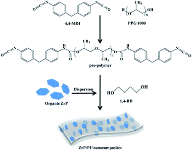
Methylene diphenyl diisocyanate (MDI, 8.0 g) and polypropylene glycol (PPG, Mn = 1000, 10.0 g) were used to synthesize the PU pre-polymer. The components were reacted in DMF at 80 °C while mechanically stirring under nitrogen flow for 2 h. The desired amount of ZrP suspended in DMF was then added, followed by stirring for 2 h. Finally, the chain extender 1,4-butanediol (1,4-BD) was added to increase the pre-polymer size during a 2 h reaction. The as-prepared ZrP/PU solution was subsequently cast onto clean release paper by a scraping cutter and cured at elevated temperatures. All cast films were thermally imidized under the following conditions to complete imidization: films were heated at a rate of 0.6–1 °C min−1 to 50, 80, or 110 °C, kept isothermal at each temperature for 0.5 h, and finally heated to 110 °C for 6 h. The molar ratio of MDI to PPG in the pre-polymer was 3![[thin space (1/6-em)]](https://www.rsc.org/images/entities/char_2009.gif) :
:![[thin space (1/6-em)]](https://www.rsc.org/images/entities/char_2009.gif) 1, and the total NCO/OH ratio in the PU was equal to 1. By changing the addition of ZrP from 0.5 to 1, 3, and 5 wt%, a series of transparent PU nanocomposite films was successfully synthesized, coded as ZrP-0.5/PU, ZrP-1/PU, ZrP-3/PU, and ZrP-5/PU, respectively. The synthesis process of ZrP/PU nanocomposites is shown in Fig. 1.
1, and the total NCO/OH ratio in the PU was equal to 1. By changing the addition of ZrP from 0.5 to 1, 3, and 5 wt%, a series of transparent PU nanocomposite films was successfully synthesized, coded as ZrP-0.5/PU, ZrP-1/PU, ZrP-3/PU, and ZrP-5/PU, respectively. The synthesis process of ZrP/PU nanocomposites is shown in Fig. 1.
2.4 Characterization
The external morphology of ZrP and ZrP/PU nanocomposite films were observed by using field-emission scanning electron microscopy (FESEM, JSM-7100, JEOL, Japan), and field emission transmission electron microscope (FETEM, JEM-2100F, JEOL, Japan). The characterizations of ZrP/PU nanocomposites have been by analyzed instrument of attenuated total reflection Fourier transform infrared spectrometer (ATR-FTIR) application a Nicolet-380 spectrometer (Thermo, U.S.), and high resolution X-ray diffractometer (XRD, PANalytical X'Pert3 powder). The optical performance, including transmittance, haze of spin-coated thin films was inspected by a UV-Vis spectrometer (JASCO V-750). The water vapor transmission rate of each specimen with the size of 20 cm2 was analyzed with a interpenetration test system (WVTR, Permatran-W 3/61, MOCON) at atmospheric pressure, 40 °C and 100% relative humidity (RH). Electrochemical tests of coated and uncoated mild steel strip were advanced in a conventional three electrode flat glass cell using an electrochemical workstation zive sp1 (Wonatech, Korea) in 3.5 wt% NaCl solutions.The three electrodes are Ag/AgCl as consultation, platinum as accessorial, and test sample as the operating electrode. A total of 1.0 cm2 area of operating electrode was uncovered to the solution. Before the electrochemical experiment, the operating electrode was approved to stabilize for 20 minutes, and then its open circuit potential (OCP) was calendared as a function of time for 600 seconds. After OCP stabilization, impedance measurements were made at exceptional corrosion potentials (Ecorr) over a frequency reach of 100 kHz to 0.1 Hz, with a signal vibration amplitude perturbation of 10 mV. Potentiodynamic polarization studies were conducted in the potential range of ±250 mV at 0.002 mV s−1 scan rate. The Tafel and impedance parameters were collected by curve fitting programs available in the software. Corrosion current density (Icorr) was determined by superimposing a straight line along the linear portion of cathodic or anodic curve and extrapolating it through Ecorr. Corrosion rate (CR, in mm per year) was calculated using the following equation:32,33
3. Results and discussion
3.1 Synthesis and characterization of ZrP, PU and ZrP/PU
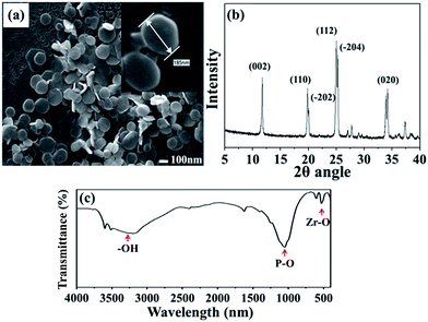
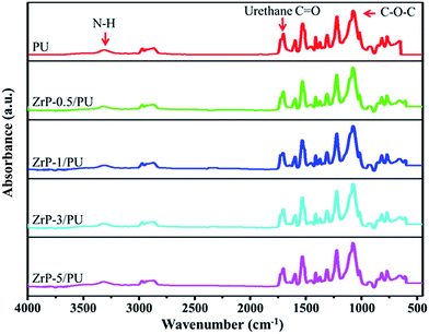
The SEM image in Fig. 2(a) shows that ZrP nanoplatelets were basically regular in shape.34,35 These ZrP nanoplatelets had similar sizes, with a mean length of about 100–200 nm. The XRD spectrum of ZrP is shown in Fig. 2(b). The first strong refraction peak of ZrP at 2θ = 11.6° corresponds to the ZrP interlayer of (002), the second refraction peaks of ZrP at 2θ = 19.7° and 20.1° represent the ZrP interlayer of (110) and (−202). The third refraction peaks of ZrP at 2θ = 24.9° and 25.3° indicate the ZrP interlayer of (112) and (−204).36–38 The chemical structure of the ZrP nanoplatelets was characterized with an FTIR spectrometer over the spectral region of 400–4000 cm−1. As shown in Fig. 2(c), the –OH extending vibrations in water are clearly visible at 3509 and 3592 cm−1; P–OH extending vibrations are visible at 3135 cm−1; intermediate vibrations of water can be observed at 1616 and 1622 cm−1; P–OH deformation vibrations are visible at 1248 cm−1; peaks of orthophosphate groups can be identified at 1037 and 1071 cm−1; the peak at 962 cm−1 can be assigned to pyrophosphate groups; and finally, the peak at 560 cm−1 can be associated to Zr–O extending vibrations.39,40FTIR spectroscopy was also used to characterize ZrP/PU nanocomposites with varying ZrP content, with results shown in Fig. 3. Non-bonded N–H extending vibrations (∼3486 cm−1), bonded N–H extending vibrations (3316 cm−1), C–H extending vibrations (∼3000 and ∼2800 cm−1), non-bonded C![[double bond, length as m-dash]](https://www.rsc.org/images/entities/char_e001.gif) O extending vibrations (1716 cm−1), the urethane group (1689 cm−1), N–H bending and C–N extending vibrations (1523 cm−1), and C–O–C extending vibrations (1082 cm−1) could be identified.41,42 The NCO groups (2270 cm−1) could not be observed in the spectra, indicating that the synthesis process had been completed.43
O extending vibrations (1716 cm−1), the urethane group (1689 cm−1), N–H bending and C–N extending vibrations (1523 cm−1), and C–O–C extending vibrations (1082 cm−1) could be identified.41,42 The NCO groups (2270 cm−1) could not be observed in the spectra, indicating that the synthesis process had been completed.43
To probe the internal morphologies of PU and ZrP/PU nanocomposites, their cross-sections were examined by SEM imaging. Fig. 4(a) and (b) show the cross-sectional SEM images of pure PU and ZrP-5/PU, respectively. The fracture surface of ZrP-5/PU was smooth and no aggregation of ZrP could be observed. TEM was used to investigate the three-dimensional morphology of as-prepared hybrid materials. Fig. 4(c) demonstrates that the hybrid material of PU with an incorporated ZrP concentration of 5 wt% exhibited good dispersion, which can influence the optical transparency, moisture barrier, and anti-corrosion properties of polymer nanocomposites.44
 | ||
| Fig. 4 SEM images of (a) PU and (b) ZrP-5/PU nanocomposite. (c) TEM image of ZrP-5/PU nanocomposite. | ||
3.2 Optical transparency of pure PU and ZrP/PU films
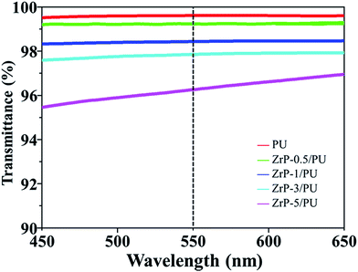
Fig. 5 shows the optical transmittance spectra of pure PU as well as ZrP/PU nanocomposite films. For pure PU, the transmittance was 99.63% at 550 nm. Although the transmittance of the nanocomposite films decreased as their ZrP content increased, the ZrP-5/PU films still retained their transparency (transmittance > 95%). For ZrP/PU films, the transmittance at 550 nm was 99.17, 98.45, 97.84, and 96.26% for ZrP contents of 0.5, 1, 3, and 5 wt%, respectively. The functional surface groups of ZrP likely facilitated the uniform dispersion of ZrP in DMF. The observed results suggest that the obtained ZrP/PU films were nearly colorless and had excellent optical transparencies.3.3 Gas barrier properties of ZrP/PU films
Films of PU and ZrP/PU materials used for molecular barrier measurements were prepared to have a thickness of approximately 30 μm. In comparison with PU, the ZrP/PU films exhibited lower H2O permeability, as shown in Fig. 6. The H2O permeability in terms of water vapor transmission rate (WVTR) of PU, ZrP-0.5/PU, ZrP-1/PU, ZrP-3/PU, and ZrP-5/PU was ca. 194, 164, 132, 107, and 84 g m−2 per day, respectively. Thus, a significant decrease in WVTR was observed due to the addition of 5 wt% ZrP to the PU matrix. The good dispersion of ZrP in the PU matrix may have effectively extended the path of the water vapor passing through the hybrid film and thereby significantly improved the water vapor barrier property.45,46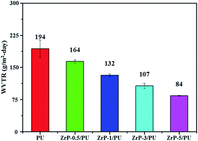 | ||
| Fig. 6 WVTR of pure PU and ZrP/PU films. Note: WVTR was measured at a temperature of 40 °C and relative humidity (RH) of 100%. | ||
3.4 Potentiodynamic measurements
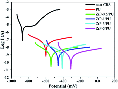
For the corrosion protection experiments, a series of electrochemical measurements of PU and ZrP/PU coatings on CRS electrodes was used to investigate anti-corrosion effects in a 3.5 wt% NaCl aqueous solution. The measured corrosion potential (Ecorr), polarization resistance (Rp), corrosion rate (CR), and corrosion current density (Icorr) values are given in Table 1. Generally, a higher Ecorr and lower Icorr, Rp, and CR indicate better corrosion protection. The potentiodynamic polarization curves for PU and ZrP/PU coatings are shown in Fig. 7. The Icorr and Ecorr of pure uncoated CRS were 4.2 × 10⁻⁶ A cm−2 and −873 mV, respectively. However, after coating CRS with PU and ZrP/PU nanocomposite films, the Icorr decreased to 4.28 × 10⁻⁸ A cm−2 for a pure PU coating and to as low as 1.21 × 10⁻⁹ A cm−2 for a ZrP-5/PU coating. The corresponding Ecorr increased from −606 mV for pure PU-coated CRS to −307 mV for ZrP-5/PU-coated CRS. The anti-corrosion properties of several other polymer nanocomposite coatings reported in the literature are provided in ESI, Table S1.†| Sample name | Electrochemical measurements | ||||
|---|---|---|---|---|---|
| Ecorr (mV) | Rp (kΩ cm2) | Icorr (A cm−2) | CR (mm per year) | Thickness (μm) | |
| Neat CRS | −873 | 4.12 | 4.20 × 10⁻⁶ | 48.92 | — |
| PU | −606 | 1.40 × 10³ | 4.28 × 10⁻⁸ | 5.01 × 10⁻⁴ | 30 |
| ZrP-0.5/PU | −546 | 1.35 × 10⁴ | 2.71 × 10⁻⁹ | 3.17 × 10⁻⁵ | 36 |
| ZrP-1/PU | −455 | 1.66 × 10⁴ | 2.07 × 10⁻⁹ | 2.43 × 10⁻⁵ | 34 |
| ZrP-3/PU | −417 | 2.03 × 10⁴ | 1.95 × 10⁻⁹ | 2.28 × 10⁻⁵ | 32 |
| ZrP-5/PU | −307 | 3.17 × 10⁴ | 1.21 × 10⁻⁹ | 1.42 × 10⁻⁵ | 35 |
The CR was estimated to be 48.9 mm per year for bare CRS. Meanwhile, the CR of ZrP-5/PU-coated CRS was greatly lowered to 1.42 × 10⁻⁵ mm per year, 35 times less than that observed for PU-coated CRS (5.01 × 10⁻⁴ mm per year).
The Rp was evaluated from Tafel plots, according to the Stern–Geary equation:46–48
![[thin space (1/6-em)]](https://www.rsc.org/images/entities/char_2009.gif) I), respectively.
I), respectively.
The ZrP-5/PU coating exhibited the best anti-corrosion capability, as evidenced by its highest and lowest values for Ecorr and Icorr (which correspond to a lower corrosion rate), respectively, compared to pure CRS and PU-coated CRS. The enhanced corrosion protection mechanism of the ZrP/PU coatings might be the increased tortuosity of diffusion pathways due to well-dispersed ZrP. The corrosion process in neutral solutions is presented in the following equations:27,45
| Fe → Fe2+ + 2e− |
| Fe2+ → Fe3+ + e− |
| O2(g) + 2H2O + 4e− → 4OH− |
| 4Fe2+(aq) + O2(g) + 6H2O → 4FeOOH + 8H+ |
It is known that, to cause corrosion, sufficient H2O is required for the formation of rust and dissolution of steel. Effective prevention of corrosion of a metal substrate can therefore be achieved if H2O is prevented from accessing its surface, which might be achieved by an increase in the tortuosity of diffusion pathways. For this reason, increased tortuosity may lead to good anti-corrosion properties.
3.5 Electrochemical impedance spectroscopy (EIS)
EIS is a powerful tool to study the corrosion protection mechanism of coatings. The magnitude of impedance was used to determine the resistance of coatings to the transportation of electrons and charges. Differences of several orders of magnitude in impedance were observed, as shown in the Nyquist plots (Fig. 8). The Nyquist plots of all samples were nearly semicircle arcs. We found that the charge transfer resistances of the samples, as determined by the intersection of the low frequency end of each semicircle arc with the real axis, were 14, 2.93 × 10⁵, 4.46 × 10⁵, 6.42 × 10⁵, 8.28 × 10⁵, and 10.09 × 10⁵ Ω, respectively. The nanocomposite coatings thus served as effective physical barriers to prevent corrosive ions in the electrolyte from penetrating the coating to induce corrosion of the steel. These results clearly demonstrate that the samples with the highest ZrP content exhibited the best corrosion protection performance.49,50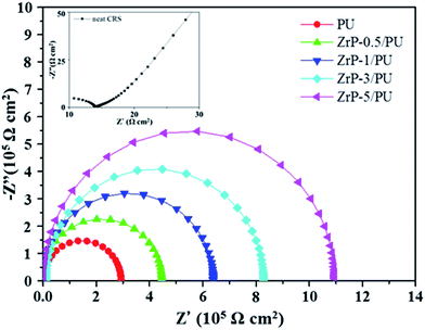 | ||
| Fig. 8 Nyquist plots for PU and ZrP/PU films measured in 3.5 wt% aqueous NaCl solution. The inset shows the Nyquist plots for neat CRS. | ||
4. Conclusions
This study is the first to report the preparation and corrosion protection performance of a series of hybrid nanocomposite materials of polyurethane (PU) and α-zirconium phosphate (ZrP). Compared to pure PU films, ZrP/PU nanocomposite films with a low ZrP content (e.g., 5 wt%) show a reduction of about 40% in H2O permeability. The reduced H2O permeability was attributed to the good dispersion of the ZrP filler material, which increased the length of H2O gas diffusion pathways. A series of electrochemical studies was conducted on the corrosion protection properties of the ZrP/PU nanocomposite coatings. The corrosion potential and polarization resistance increased, whereas the corrosion current and the corrosion rate decreased with an increase in ZrP content, confirming that ZrP–PU coatings provide effective anti-corrosion protection. The ZrP/PU nanocomposites showed superior corrosion inhibition, suggesting that they have great potential for use in the anti-corrosion coating industry.Acknowledgements
This research was supported by the National Science council of Republic of China under grant number MOST-105-2221-E-167-033.References
- G. F. Hays, Raising Awareness About Corrosion and Corrosion Protection Around the World, World Corrosion Organization, 2016 Search PubMed.
- A. R. Marder, Prog. Mater. Sci., 2000, 45, 191–271 CrossRef CAS.
- X. He, C. Chiu, M. J. Esmacher and H. Liang, Surf. Coat. Technol., 2013, 237, 320–327 CrossRef CAS.
- T.-C. Huang, T.-C. Yeh, H.-Y. Huang, W.-F. Ji, Y.-C. Chou, W.-I. Hung, J.-M. Yeh and M.-H. Tsai, Electrochim. Acta, 2011, 56, 10151–10158 CrossRef CAS.
- X. Yao, Y. Song and L. Jiang, Adv. Mater., 2011, 23, 719–734 CrossRef CAS PubMed.
- T.-C. Yeh, T.-C. Huang, H.-Y. Huang, Y.-P. Huang, Y.-T. Cai, S.-T. Lin, Y. Wei and J.-M. Yeh, Polym. Chem., 2012, 3, 2209–2216 RSC.
- T.-I. Yang, C.-W. Peng, Y. L. Lin, C.-J. Weng, G. Edgington, A. Mylonakis, T.-C. Huang, C.-H. Hsu, J.-M. Yeh and Y. Wei, J. Mater. Chem., 2012, 22, 15845–15852 RSC.
- T.-C. Huang, Y.-A. Su, T.-C. Yeh, H.-Y. Huang, C.-P. Wu, K.-Y. Huang, Y.-C. Chou, J.-M. Yeh and Y. Wei, Electrochim. Acta, 2011, 56, 6142–6149 CrossRef CAS.
- Y.-H. Yu, Y.-Y. Lin, C.-H. Lin, C.-C. Chan and Y.-C. Huang, Polym. Chem., 2014, 5, 535–550 RSC.
- R. Yuan, S. Wu, B. Wang, Z. Liu, L. Mu, T. Ji, L. Chen, B. Liu, H. Wang and J. Zhu, Polymer, 2016, 85, 37–46 CrossRef CAS.
- T. C. Huang, L. C. Yeh, G. H. Lai, F. Y. Lai, T. I. Yang, Y. J. Huang, A. Y. Lo and J. M. Yeh, eXPRESS Polym. Lett., 2016, 10, 450–461 CrossRef CAS.
- Polyurethanes Book, ed. D. R. S. Lee, 2003 Search PubMed.
- T.-C. Huang, C.-F. Hsieh, T.-C. Yeh, C.-L. Lai, M.-H. Tsai and J.-M. Yeh, J. Appl. Polym. Sci., 2011, 119, 548–557 CrossRef CAS.
- Y. T. Park, Y. Qian, C. I. Lindsay, C. Nijs, R. E. Camargo, A. Stein and C. W. Macosko, ACS Appl. Mater. Interfaces, 2013, 5, 3054–3062 CAS.
- A. Mishra, B. P. D. Purkayastha, J. K. Roy, V. K. Aswal and P. Maiti, Macromolecules, 2010, 43, 9928–9936 CrossRef CAS.
- G. Findenig, S. Leimgruber, R. Kargl, S. Spirk, K. Stana-Kleinschek and V. Ribitsch, ACS Appl. Mater. Interfaces, 2012, 4, 3199–3206 CAS.
- L. Sun, W. J. Boo, A. Clearfield, H. J. Sue and H. Q. Pham, J. Membr. Sci., 2008, 318, 129–136 CrossRef CAS.
- N. Sarkar, G. Sahoo, R. Das, G. Prusty, D. Sahu and S. K. Swain, Ind. Eng. Chem. Res., 2016, 55, 2921–2931 CrossRef CAS.
- W. Sun, L. Wang, T. Wu, Y. Pan and G. Liu, J. Electrochem. Soc., 2016, 163, C16–C18 CrossRef CAS.
- H. Koerner, G. Price, N. A. Pearce, M. Alexander and R. A. Vaia, Nat. Mater., 2004, 3, 115–120 CrossRef CAS PubMed.
- H. Wei, D. Ding, S. Wei and Z. Guo, J. Mater. Chem. A, 2013, 1, 10805–10813 CAS.
- I. H. Tseng, Y.-F. Liao, J.-C. Chiang and M.-H. Tsai, Mater. Chem. Phys., 2012, 136, 247–253 CrossRef CAS.
- P. Li, T.-C. Huang, K. L. White, S. Hawkins, M. Kotaki, R. Nishimura and H.-J. Sue, RSC Adv., 2015, 5, 102633–102642 RSC.
- I. H. Tseng, M.-H. Tsai and C.-W. Chung, ACS Appl. Mater. Interfaces, 2014, 6, 13098–13105 CAS.
- P. Li, X. He, T.-C. Huang, K. L. White, X. Zhang, H. Liang, R. Nishimura and H.-J. Sue, J. Mater. Chem. A, 2015, 3, 2669–2676 CAS.
- L. Sun, W. J. Boo, H.-J. Sue and A. Clearfield, New J. Chem., 2007, 31, 39–43 RSC.
- K. Cai, S. Zuo, S. Luo, C. Yao, W. Liu, J. Ma, H. Mao and Z. Li, RSC Adv., 2016, 6, 95965–95972 RSC.
- T. Zhang, L. Kong, Y. Dai, X. Yue, J. Rong, F. Qiu and J. Pan, Chem. Eng. J., 2017, 309, 7–14 CrossRef CAS.
- M. Moradi, H. Yeganeh and S. Pazokifard, RSC Adv., 2016, 6, 28089–28102 RSC.
- M. Kashif and S. Ahmad, RSC Adv., 2014, 4, 20984–20999 RSC.
- M. Wong, R. Ishige, K. L. White, P. Li, D. Kim, R. Krishnamoorti, R. Gunther, T. Higuchi, H. Jinnai, A. Takahara, R. Nishimura and H.-J. Sue, Nat. Commun., 2014, 5, 3589 Search PubMed.
- T.-C. Huang, T.-C. Yeh, H.-Y. Huang, W.-F. Ji, T.-C. Lin, C.-A. Chen, T.-I. Yang and J.-M. Yeh, Electrochim. Acta, 2012, 63, 185–191 CrossRef CAS.
- T.-C. Huang, L.-C. Yeh, G.-H. Lai, B.-S. Huang, T.-I. Yang, S.-C. Hsu, A.-Y. Lo and J.-M. Yeh, Int. J. Green Energy, 2017, 14, 113–120 CrossRef CAS.
- C. Trobajo, S. A. Khainakov, A. Espina and J. R. García, Chem. Mater., 2000, 12, 1787–1790 CrossRef CAS.
- B. M. Mosby, M. Goloby, A. Díaz, V. Bakhmutov and A. Clearfield, Langmuir, 2014, 30, 2513–2521 CrossRef CAS PubMed.
- Y. Zhou, R. Huang, F. Ding, A. D. Brittain, J. Liu, M. Zhang, M. Xiao, Y. Meng and L. Sun, ACS Appl. Mater. Interfaces, 2014, 6, 7417–7425 CAS.
- B. M. Mosby, A. Díaz, V. Bakhmutov and A. Clearfield, ACS Appl. Mater. Interfaces, 2014, 6, 585–592 CAS.
- H. Xiao, W. Dai, Y. Kan, A. Clearfield and H. Liang, Appl. Surf. Sci., 2015, 329, 384–389 CrossRef CAS.
- S. Kantheti, R. Narayan and K. V. S. N. Raju, Ind. Eng. Chem. Res., 2014, 53, 8357–8365 CrossRef CAS.
- A. Díaz, B. M. Mosby, V. I. Bakhmutov, A. A. Martí, J. D. Batteas and A. Clearfield, Chem. Mater., 2013, 25, 723–728 CrossRef.
- C.-J. Chen, M.-H. Tsai, I. H. Tseng, A.-W. Hsu, T.-C. Liu and S.-L. Huang, RSC Adv., 2013, 3, 9729–9738 RSC.
- S. Chen, F. Mo, Y. Yang, F. J. Stadler, S. Chen, H. Yang and Z. Ge, J. Mater. Chem. A, 2015, 3, 2924–2933 CAS.
- H.-Y. Huang, T.-C. Huang, J.-C. Lin, J.-H. Chang, Y.-T. Lee and J.-M. Yeh, Mater. Chem. Phys., 2013, 137, 772–780 CrossRef CAS.
- M.-H. Tsai, I. H. Tseng, Y.-F. Liao and J.-C. Chiang, Polym. Int., 2013, 62, 1302–1309 CrossRef CAS.
- C.-H. Chang, T.-C. Huang, C.-W. Peng, T.-C. Yeh, H.-I. Lu, W.-I. Hung, C.-J. Weng, T.-I. Yang and J.-M. Yeh, Carbon, 2012, 50, 5044–5051 CrossRef CAS.
- X. Sheng, W. Cai, L. Zhong, D. Xie and X. Zhang, Ind. Eng. Chem. Res., 2016, 55, 8576–8585 CrossRef CAS.
- G. Qu, F. Li, E. B. Berda, M. Chi, X. Liu, C. Wang and D. Chao, Polymer, 2015, 58, 60–66 CrossRef CAS.
- F. Li, M. Zhou, J. Wang, X. Liu, C. Wang and D. Chao, Synth. Met., 2015, 205, 42–47 CrossRef CAS.
- M. Yin, F. Li, Y. Yan, X. Liu, C. Wang and D. Chao, J. Polym. Sci., Part A: Polym. Chem., 2016, 54, 2321–2330 CrossRef CAS.
- L. Shahhosseini, M. R. Nateghi, M. Kazemipour and M. B. Zarandi, Prog. Org. Coat., 2015, 88, 272–282 CrossRef CAS.
Footnote |
| † Electronic supplementary information (ESI) available. See DOI: 10.1039/c6ra27588e |
| This journal is © The Royal Society of Chemistry 2017 |

