
 Open Access Article
 This Open Access Article is licensed under a
 Creative Commons Attribution 3.0 Unported Licence
Encapsulation of an ionic liquid into the nanopores of a 3D covalent organic framework†
Yingxiang Xinab,
Chang Wang*b,
Yu Wangb,
Jianjun Sun*a and
Yanan Gao *b
*b
aCollege of Chemical Engineering, Beijing University of Chemical Technology, Beijing, 100029, China. E-mail: sunjj@mail.buct.edu.cn
bDalian Institute of Chemical Physics, Chinese Academy of Sciences, 457 Zhongshan Road, Dalian 116023, China. E-mail: chill@dicp.ac.cn; ygao@dicp.ac.cn
First published on 5th January 2017
Abstract
An ionic liquid was confined inside the nanopores of a three-dimensional (3D) COF for the first time. The confined ionic liquid was remarkably solidified due to the nanosized effect of the COF on the ionic liquid. This research provides a novel strategy for immobilizing ionic liquids on solid supports or within a solid matrix.
Ionic liquids (ILs) have received extensive attention due to their appealing properties, such as negligible volatility, nonflammability, high ionic conductivity, and excellent thermal stability.1 In terms of these properties, ILs have been widely used as alternative media for chemical reactions,2 extraction or separation,3 and electrochemical applications.4 The behavior of different materials confined in nano-pores has recently opened up interesting possibilities both from the point of basic understanding and technological applications. Many interesting phenomena have been reported regarding the effects of confinement on changes in the dynamic (viscosity, diffusion coefficient, conductivity), thermal (phase transition and stability), and optical (fluorescence) properties of confined species.5 The confinement of ILs in nano-pores has shown dramatic effects on their physical properties, like melting point,6 crystal structure,7 chemical reactivity8 and gas separation characteristics.9 These changes have been explained on the basis of interaction of pore wall of confining matrix with confined ILs.10 Moreover, these changes are much dependent on the intrinsic characteristics of porous matrices. For instance, the melting point of ionic liquids is decreased when confined in the inorganic silica matrix,6 while a solidify behavior of room-temperature IL was obtained when ILs are confined into multi-walled carbon nanotubes.11 Recently, confinement of ILs in a hybrid porous material, metal–organic frameworks (MOFs), has been reported and the resulted ILs–MOF hybrid materials exhibited a high gas selectivity and high catalytic activity compared to the bulk ILs.12
Covalent organic frameworks (COFs) represent an exciting new type of porous organic materials, which are ingeniously constructed with organic building units via strong covalent bonds. They have attracted considerable scientific interest due to their large specific surface areas and pore volumes, regular and accessible pores, and crystalline open structures.13 These porous solids are promising materials for potential applications in gas storage, separation and heterogeneous catalysis.14 Earlier few studies on the effect of confinement have been reported for molecular liquids15 and volatile organometallic compounds16 in the nanopores of COFs. The unique arrangement of ferrocene molecules inside COF-102 is driven by π–π (host–guest) interactions and replicates the framework symmetry. The somewhat flexible nature of the framework is revealed by the decrease of cell parameter in the case of [Ru(cod)(cot)]2@COF-102. However, there has been no report on confinement of ILs into the nanopores of COFs by far.
Herein, we report the confinement of a common ionic liquid, 1-ethyl-3-methylimidazolium bis(trifluoromethylsulfonyl)imide ([Emim][Tf2N]) into the nanopores of a 3D COF-320 (Fig. 1).17 The confined [Emim][Tf2N] demonstrated no phase transitions in a wide temperature range of −160–190 °C.
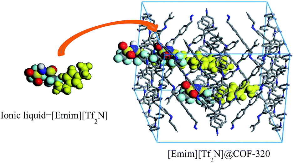 | ||
| Fig. 1 Representation of the incorporation of [Emim][Tf2N] into the nanopores of the COF-320. | ||
Ionic liquid [Emim][Tf2N] and COF-320 (see the syntheses in the ESI†) have been dramatically dried under vacuum. [Emim][Tf2N] was then mixed with activated COF-320 in a mortar at volumetric occupancy ratios of 0.25![[thin space (1/6-em)]](https://www.rsc.org/images/entities/char_2009.gif) :1, 1:1 and 2:1, respectively. The samples are heated at 90 °C for overnight so that the embedded [Emim][Tf2N] was uniformly diffused into the micropores of COF-320. The COFs embedded with [Emim][Tf2N] were denoted as 25% IL@COF-320, 100% IL@COF-320 and 200% IL@COF-320, respectively. As shown in the PXRD patterns (Fig. 2), the peak intensities of COF-320 were obviously decreased when [Emim][Tf2N] was embedded. Even only 25% [Emim][Tf2N] was used, the (020) diffraction peak decreased strongly. Considering that COFs are composed of light elements, like C, H and N, etc., the decreased intensities of the XRD peaks do not mean that the crystal structure of COF-320 was destroyed after mixing with [Emim][Tf2N]. Similar observations have been reported for other COFs that were caused by amorphous alkyl chains on the walls or guest molecules incorporated within the pores of the COFs.16,18 Some different new diffraction peaks appeared when IL was embedded into the nanopores of COF-320, suggesting that the [Emim][Tf2N] may be solidified when confined in a limited space.11b
:1, 1:1 and 2:1, respectively. The samples are heated at 90 °C for overnight so that the embedded [Emim][Tf2N] was uniformly diffused into the micropores of COF-320. The COFs embedded with [Emim][Tf2N] were denoted as 25% IL@COF-320, 100% IL@COF-320 and 200% IL@COF-320, respectively. As shown in the PXRD patterns (Fig. 2), the peak intensities of COF-320 were obviously decreased when [Emim][Tf2N] was embedded. Even only 25% [Emim][Tf2N] was used, the (020) diffraction peak decreased strongly. Considering that COFs are composed of light elements, like C, H and N, etc., the decreased intensities of the XRD peaks do not mean that the crystal structure of COF-320 was destroyed after mixing with [Emim][Tf2N]. Similar observations have been reported for other COFs that were caused by amorphous alkyl chains on the walls or guest molecules incorporated within the pores of the COFs.16,18 Some different new diffraction peaks appeared when IL was embedded into the nanopores of COF-320, suggesting that the [Emim][Tf2N] may be solidified when confined in a limited space.11b
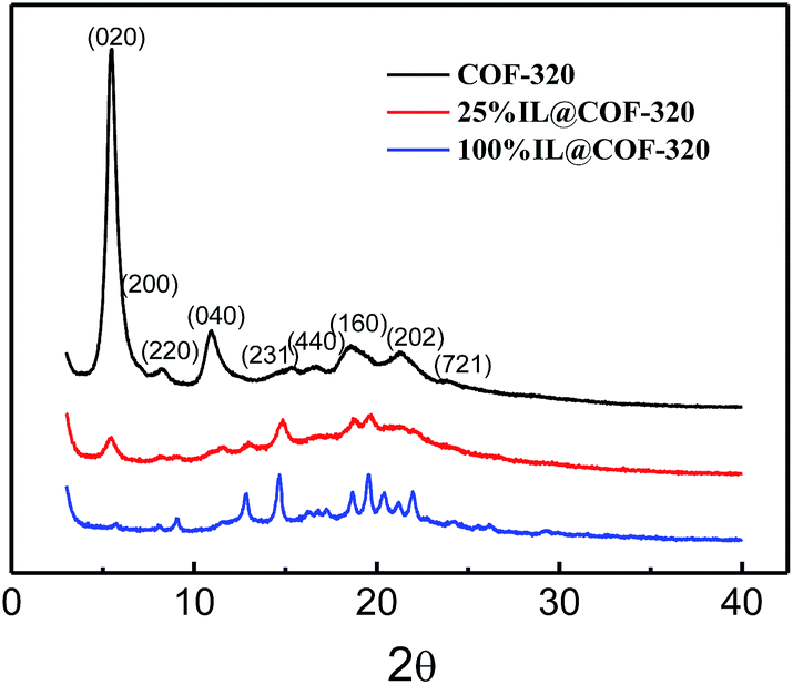 | ||
| Fig. 2 Powder XRD patterns of COF-320, 25% IL@COF-320 and 100% IL@COF-320. | ||
Nitrogen gas adsorption measurements were conducted at 77 K to confirm the presence of [Emim][Tf2N] inside the nanopores of the COF. Fig. 3 show the N2 adsorption and desorption isotherms. The similar type of adsorption was observed both with 25% and without incorporated [Emim][Tf2N]. This result indicates that the microporous nature was maintained even after introduction of small amounts of IL. The Langmuir surface area was decreased from 1812 to 609 m2 g−1 and the pore volume of COF-320 was decreased by 52% (from 1.00 to 0.48 cm3 g−1) after the introduction of 25% [Emim][Tf2N]. This result is larger than that of theoretical calculated value (25%), which can be attributed to the one-dimensional (1D) channel structure of COF-320. COF-320 possesses a 9-fold interwoven diamond net structure17 and the bis-imine conjugated linkers comprise the close-packed π-electron walls of 1D channels. The confined [Emim][Tf2N] was probably diffused along the linear channels during the heating process. As a result, [Emim][Tf2N] molecules occupied more space than the theoretical value. Certainly, there is scarcely gas absorption and pore volume when 100% and 200% IL loaded.
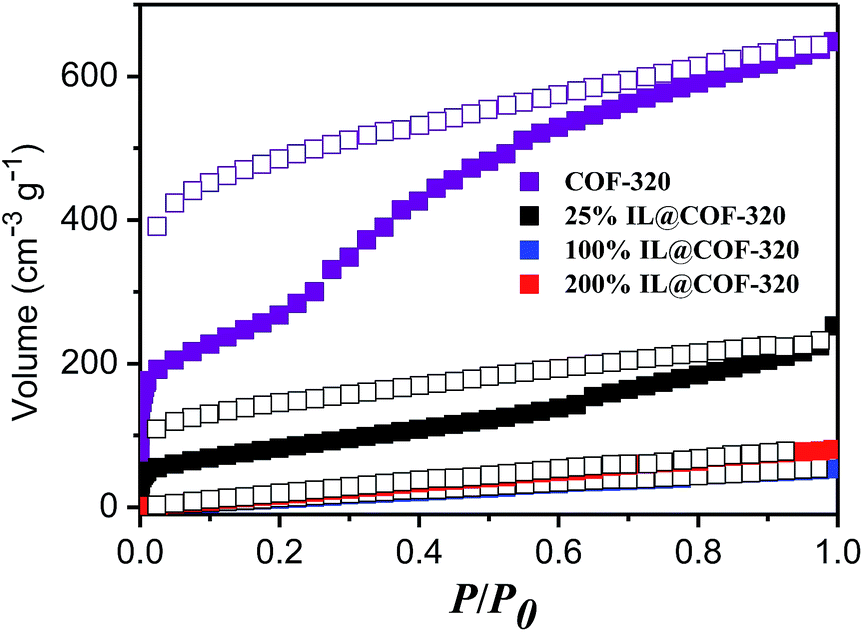 | ||
| Fig. 3 N2 adsorption (open symbols) and desorption (closed symbols) isotherms of COF-320 and [Emim][Tf2N]@COF-320 at different volumetric occupancy at 77 K. | ||
The FTIR spectra of [Emim][Tf2N], COF-320, and [Emim][Tf2N]@COF-320 are shown in Fig. 4. [Emim][Tf2N]@COF-320 shows a blue shift from the bands of the bulk [Emim][Tf2N], such as bands at 1178, 610, and 508 cm−1 in the FTIR spectrum assigned to [Emim][Tf2N]. The blue-shifted bands can be attributed to the disaggregation of the ions into a few ion pairs owing of nanosizing within the micropores of COF-320.19 Based on the N2 adsorption and FTIR measurements, it can be concluded that [Emim][Tf2N] was successfully introduced into the nanopores of COF-320.
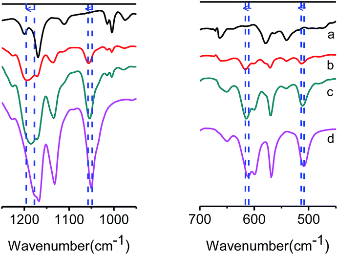 | ||
| Fig. 4 FTIR spectra of (a) COF-320 (black), [Emim][Tf2N]@COF-320 at volumetric occupancy of (b) 25% (red) and (c) 100% (olive), and (d) bulk [Emim][Tf2N] (pink). Blue dashed lines show blue shift of IR absorption. | ||
Differential scanning calorimetry (DSC) measurements were also carried out to detect possible phase transitions of confined [Emim][Tf2N]. Fig. 5 shows the measured the DSC diagrams. The bulk [Emim][Tf2N] showed sharp peaks at −11 °C upon heating and at −46 °C upon cooling. The peak at −11 °C can be ascribed to the melting and the peak at −46 °C was due to freezing. The freezing temperature being lower than the melting temperature was attributed to the supercooling behavior of the liquid state.20 However, [Emim][Tf2N]@COF-320 showed no peaks between −160 and 190 °C in the DSC measurements at volumetric occupancy of 25% and 100% IL. We did not even observe the phase transition upon heating until the decomposition temperature of [Emim][Tf2N]@COF-320 (432.3 °C for 25% IL@COF-320 and 409.5 °C for 100% IL@COF-320) (Fig. S1, in ESI†). This result confirms that the confined [Emim][Tf2N] in COF-320 nanopores was solidified remarkably. Similar phase behavior appeared at almost the same temperatures of the melting and freezing of the bulk [Emim][Tf2N] only in the case of 200% IL@COF-320. This phenomenon can be explained by the melting and freezing of the excess [Emim][Tf2N] molecules located outside the nanopores of COF-320.
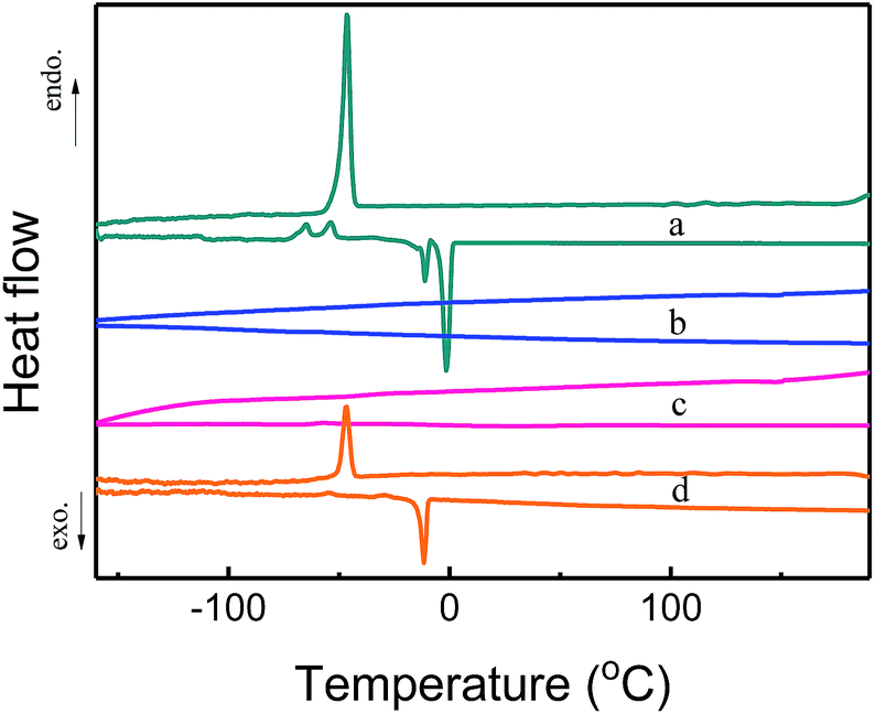 | ||
| Fig. 5 DSC curves of bulk [Emim][Tf2N] (a) and [Emim][Tf2N]@COF-320 at volumetric occupancies of 25% (b), 100% (c) and 200% (d). Endo = endothermic heat flow, exo = exothermic heat flow. | ||
Furthermore, the solid-state 19F NMR was further used to assess the guest–host behavior through the analysis of the motion of TFSA− anions. The observed volumetric occupancies dependences of the 19F NMR spectra for the nanosized [Emim][Tf2N] in COF-320 are shown in Fig. 6. In the 200% IL@COF-320 spectra, a sharp peak appeared at −78.5 ppm that superimposed on a small broad signal on the left. This sharp peak can be assigned to the [Emim][Tf2N] in the liquid state21 where the Tf2N− anions rotate and diffuse freely. Briefly, this sharpening line can be explained by “motional narrowing”. On the contrast, the small broad signal is due to the [Emim][Tf2N] confined within the nanopores of COF-320, which reflect that the phase transition behavior of the confined [Emim][Tf2N] was obviously different from that of the bulk [Emim][Tf2N]. The peak intensity decreased for the sharp peak and concomitantly increased for the broad peak when the volumetric occupancy of [Emim][Tf2N] is 100%. The broad peak of confined [Emim][Tf2N] accompanied by the sharp peak of free [Emim][Tf2N] reveals that some [Emim][Tf2N] is out of the nanopores of COF-320, which is in accordance with the N2 adsorption measurements that [Emim][Tf2N] occupied more space than that of the theoretical calculated value. Only the broad signal of [Emim][Tf2N] was observed for the 25% IL@COF-320, indicating that the nanosized [Emim][Tf2N] is dynamically limited in the micropores of COF-320. The COF-320 composed of pure organic units and there exists potentially various noncovalent-bonding interactions between the channel walls of COF-320 and [Emim][Tf2N] molecules, like van der Waals force, hydrogen bonds, hydrophobic interactions, etc. Such interactions are known to lead to the appearance of host–guest chemistry in supramolecular chemistry field. We suppose that these wide interactions between the channel walls of COF-320 and [Emim][Tf2N] are responsible for the abnormal phase behavior of [Emim][Tf2N].
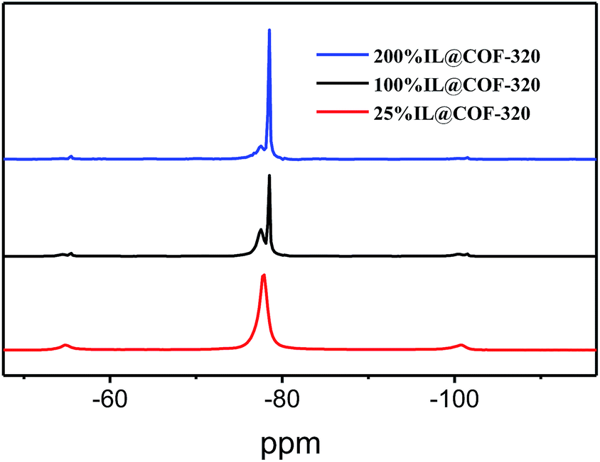 | ||
| Fig. 6 Solid-state 19F NMR spectra of [Emim][Tf2N]@COF-320 at different volumetric occupancies. | ||
In summary, we have demonstrated the first example of an IL incorporated within the nanopores of a 3D COF. The successful incorporation of [Emim][Tf2N] was confirmed by PXRD, N2 adsorption measurements, FTIR experiments, DSC and solid-state 19F NMR spectra. The confined [Emim][Tf2N] within the nanopores of COF-320 exhibited no phase transition down to −160 °C and up to 190 °C. The solid-state 19F NMR spectra further revealed that the [Emim][Tf2N] confined within the nanopores of COF-320 was solidified dramatically. It was speculated that wide non-covalent interactions between the channel walls of COF-320 and [Emim][Tf2N] contributed to the abnormal phase behavior. This result provides a novel strategy for immobilizing ionic liquids on solid supports or within a solid matrix. We further expect that this new type of materials would be applied in the catalysis reaction and gas separation field.
Acknowledgements
The authors gratefully acknowledge financial support from the National Natural Science Foundation of China (21273235 and 21473196), and the One Hundred Talent Program of CAS for Gao YA.Notes and references
- (a) C. P. Mehnert, R. A. Cook, N. C. Dispenziere and M. Afeworki, J. Am. Chem. Soc., 2002, 124, 12932–12933 CrossRef CAS PubMed; (b) T. Welton, Chem. Rev., 1999, 99, 2071–2083 CrossRef CAS PubMed; (c) M. J. Earle and K. R. Seddon, Pure Appl. Chem., 2000, 72, 1391–1398 CrossRef CAS.
- (a) J. P. Hallett and T. Welton, Chem. Rev., 2011, 111, 3508–3576 CrossRef CAS PubMed; (b) E. R. Parnham and R. E. Morris, Acc. Chem. Res., 2007, 40, 1005–1013 CrossRef CAS PubMed.
- J. G. Huddleston, H. D. Willauer, R. P. Swatloski, A. E. Visser and R. D. Rogers, Chem. Commun., 1998, 1765–1766 RSC.
- P. Hapiot and C. Lagrost, Chem. Rev., 2008, 108, 2238–2264 CrossRef CAS PubMed.
- (a) H. K. Christenson, J. Phys.: Condens. Matter, 2001, 13, R95–R133 CrossRef CAS; (b) M. Heuberger, M. Zach and N. D. Spencer, Science, 2001, 292, 905–908 CrossRef CAS PubMed; (c) I. Brovchenko, A. Geiger and A. Oleinikova, J. Chem. Phys., 2004, 120, 1958–1972 CrossRef CAS PubMed; (d) Y. Shu, L. Han, X. Wang, X. Chen and J. Wang, ACS Appl. Mater. Interfaces, 2013, 5, 12156–12162 CrossRef CAS PubMed; (e) M. Waechtler, M. Sellin, A. Stark, D. Akcakayiran, G. Findenegg, A. Gruenberg, H. Breitzke and G. Buntkowsky, Phys. Chem. Chem. Phys., 2010, 12, 11371–11379 RSC; (f) C. Iacob, J. R. Sangoro, W. K. Kipnusu, R. Valiullin, J. Kärger and F. Kremer, Soft Matter, 2012, 8, 289–293 RSC; (g) D. Weingarth, R. Drumm, A. Foelske-Schmitz, R. Kotz and V. Presser, Phys. Chem. Chem. Phys., 2014, 16, 21219–21224 RSC; (h) J. Le Bideau, L. Viau and A. Vioux, Chem. Soc. Rev., 2011, 40, 907–925 RSC; (i) M. P. Singh, R. K. Singh and S. Chandra, ChemPhysChem, 2010, 11, 2036–2043 CAS; (j) M. P. Singh, R. K. Singh and S. Chandra, Prog. Mater. Sci., 2014, 64, 73–120 CrossRef CAS.
- (a) C. Li, X. J. Guo, Y. X. He, Z. Jiang, Y. X. Wang, S. M. Chen, H. Y. Fu, Y. Zou, S. Dai, G. Z. Wu and H. J. Xu, RSC Adv., 2013, 3, 9618–9621 RSC; (b) R. Goebel, P. Hesemann, J. Weber, E. Moller, A. Friedrich, S. Beuermann and A. Taubert, Phys. Chem. Chem. Phys., 2009, 11, 3653–3662 RSC; (c) M. Kanakubo, Y. Hiejima, K. Minami, T. Aizawa and H. Nanjo, Chem. Commun., 2006, 17, 1828–1830 RSC.
- (a) A. K. Gupta, R. K. Singh and S. Chandra, RSC Adv., 2014, 4, 22277 RSC; (b) M. A. Neouze, J. Le Bideau, P. Gaveau, S. Bellayer and A. Vioux, Chem. Mater., 2006, 18, 3931–3936 CrossRef CAS.
- (a) B. Karimi and E. Badreh, Org. Biomol. Chem., 2011, 9, 4194–4198 RSC; (b) Q. X. Luo, M. Ji, M. H. Lu, C. Hao, J. S. Qiu and Y. Q. Li, J. Mater. Chem. A, 2013, 1, 6530 RSC; (c) B. Karimi, A. Zamani and F. Mansouri, RSC Adv., 2014, 4, 57639–57645 RSC.
- L. A. Banu, D. Wang and R. E. Baltus, Energy Fuels, 2013, 27, 4161–4166 CrossRef CAS.
- S. Shimano, H. Zhou and I. Honma, Chem. Mater., 2007, 19, 5216–5221 CrossRef CAS.
- (a) M. A. Neouze and M. Litschauer, J. Phys. Chem. B, 2008, 112, 16721–16725 CrossRef CAS PubMed; (b) S. M. Chen, G. Z. Wu, M. L. Sha and S. R. Huang, J. Am. Chem. Soc., 2007, 129, 2416–2417 CrossRef CAS PubMed; (c) S. M. Chen, K. Kobayashi, Y. Miyata, N. Imazu, T. Saito, R. Kitaura and H. Shinohara, J. Am. Chem. Soc., 2009, 131, 14850–14856 CrossRef CAS PubMed.
- (a) N. A. Khan, Z. Hasan and S. H. Jhung, Chem.–Eur. J., 2014, 20, 376–380 CrossRef CAS PubMed; (b) Y. Chen, Z. Hu, K. M. Gupta and J. Jiang, J. Phys. Chem. C, 2011, 115, 21736–21742 CrossRef CAS.
- (a) X. Feng, X. Ding and D. Jiang, Chem. Soc. Rev., 2012, 41, 6010–6022 RSC; (b) S. Y. Ding and W. Wang, Chem. Soc. Rev., 2013, 42, 548–568 RSC.
- (a) S. S. Han, J. L. Mendoza-Cortes and W. A. Goddard, Chem. Soc. Rev., 2009, 38, 1460–1476 RSC; (b) Q. Fang, S. Gu, J. Zheng, Z. Zhuang, S. Qiu and Y. Yan, Angew. Chem., Int. Ed., 2014, 53, 2878–2882 CrossRef CAS PubMed; (c) D. B. Shinde, S. Kandambeth, P. Pachfule, R. R. Kumar and R. Banerjee, Chem. Commun., 2015, 51, 310–313 RSC; (d) N. Huang, X. Chen, R. Krishna and D. Jiang, Angew. Chem., Int. Ed., 2015, 54, 2986–2990 CrossRef CAS PubMed; (e) H. Furukawa and O. M. Yaghi, J. Am. Chem. Soc., 2009, 131, 8875–8883 CrossRef CAS PubMed; (f) Y. Du, H. S. Yang, J. M. Whiteley, S. Wan, Y. H. Jin, S. H. Lee and W. Zhang, Angew. Chem., Int. Ed., 2016, 55, 1737–1741 CrossRef CAS PubMed; (g) C. R. DeBlase, K. Hernandez-Burgos, K. E. Silberstein, G. G. Rodriguez-Calero, R. P. Bisbey, H. D. Abruna and W. R. Dichtel, ACS Nano, 2015, 9, 3178–3183 CrossRef CAS PubMed.
- C. X. Yang, C. Liu, Y. M. Cao and X. P. Yan, Chem. Commun., 2015, 51, 12254–12257 RSC.
- S. B. Kalidindi, K. Yusenko and R. A. Fischer, Chem. Commun., 2011, 47, 8506–8508 RSC.
- Y. B. Zhang, J. Su, H. Furukawa, Y. Yun, F. Gandara, A. Duong, X. Zou and O. M. Yaghi, J. Am. Chem. Soc., 2013, 135, 16336–16339 CrossRef CAS PubMed.
- R. W. Tilford, S. J. Mugavero, P. J. Pellechia and J. J. Lavigne, Adv. Mater., 2008, 20, 2741–2746 CrossRef CAS PubMed.
- K. Fujie, T. Yamada, R. Ikeda and H. Kitagawa, Angew. Chem., Int. Ed., 2014, 53, 11302–11305 CrossRef CAS PubMed.
- H. L. Ngo, K. LeCompte, L. Hargens and A. B. McEwen, Thermochim. Acta, 2000, 357, 97–102 CrossRef.
- N. Li, S. Zhang, L. Zheng and T. Inoue, Langmuir, 2009, 25, 10473–10482 CrossRef CAS PubMed.
Footnote |
| † Electronic supplementary information (ESI) available. See DOI: 10.1039/c6ra27213d |
| This journal is © The Royal Society of Chemistry 2017 |