 Open Access Article
Creative Commons Attribution 3.0 Unported Licence
Preparation and characterization of a pH-responsive membrane carrier for meso-tetraphenylsulfonato porphyrin
Mingxia Wangab,
Feng Yan *ac,
Lizhi Zhaoab,
Yuzhong Zhang*ab and
Mirco Sorcid
aState Key Laboratory of Separation Membranes and Membrane Processes, Tianjin Polytechnic University, Tianjin 300387, P. R. China. E-mail: yanfeng.yxm@hotmail.com; zhangyz2004cn@vip.163.com; Fax: +86 22 83955055; Tel: +86 22 8395451 Tel: +86 22 83955806
bSchool of Materials Science and Engineering, Tianjin Polytechnic University, Tianjin 300387, P. R. China
cSchool of Environmental and Chemical Engineering, Tianjin Polytechnic University, Tianjin 300387, P. R. China
dDepartment of Chemical and Biological Engineering, Center for Biotechnology and Interdisciplinary Studies, Rensselaer Polytechnic Institute, Troy, NY 12180, USA
First published on 5th January 2017
Abstract
A pH-responsive polysulfone-graft-poly(4-vinylpyridine) (PSF-g-P4VP)-blended PSF membrane was prepared for “smart” rejection of meso-tetraphenylsulfonato porphyrin (TPPS) in the feed. The pH-responsive characteristics of the PSF-g-P4VP-blended PSF membranes were determined. The hydraulic permeation results demonstrated that the pH-responsive characteristics behaved as expected, as these were reversible and durable, and occurred with the pH value switching between 3.0 and 8.0. Water flux drastically increased from 70 to 1113 L m−2 h−1 at pH 8.0 as the content of PSF-g-P4VP polymer in the blended membrane increased from 10% to 30%. The static adsorption of TPPS on the pH-responsive blended membrane showed that the adsorption capacity dramatically depended on pH. The pH-sensitive membrane not only plays the role of a smart membrane for rejecting the aggregates of TPPS, but also induces TPPS to assemble on the membrane surface. The flux decreases, whereas the retention of TPPS increases with the decreasing pH. The value of flux was not more than 30 L m−2 h−1 at a pH below 3.0, which provides plenty of time for the self-assembly process of TPPS on the membrane surface. J-aggregates of TPPS were observed on the blended membrane surface below pH 2.5, owing to the inductive effect of cationic P4VP units, whereas J-type aggregates could be only found at pH 1.0 in an aqueous solution.
1. Introduction
Porphyrin derivatives are well known functional dyes that possess high molar extinction coefficients in the visible region. They have been extensively used as sensors, nonlinear optical materials, energy conversion devices, and solar cells.1–4 meso-Tetraphenylsulfonato porphyrin (TPPS) is a water-soluble dye and its ability to produce a singlet oxygen (1O2) is relevant to many biochemical processes, such as in photocatalysis5 and in photodynamic therapy to destroy tumors.6 There are two types of TPPS aggregates: J-aggregates (edge-to-edge stacking) and H-aggregates (face-to-face stacking).7 As illustrated in the literature,8–10 the application of TPPS strongly depends on its aggregate forms. Among these two aggregate types, J-aggregates were extensively studied due to their supramolecular chirality11 and photophysical properties for potential applications, such as in optoelectronic devices.12TPPS aggregation in solution has been extensively investigated.13–16 However, immobilizing porphyrin on the solid carriers is highly desirable for practical use.7,17–19 For this reason, a growing body of research is now focusing on the TPPS immobilization on various solid carriers. Balaji et al. prepared an optical sensor using TPPS supported by mesoporous silica for the visual detection of mercury.20 Castriciano et al. found that TPPS can be easily anchored on Nafion®.21 These membranes exhibited interesting optical properties that strongly depended on the extent of TPPS aggregation and the organic solvent used. Our group has studied the adsorption properties and self-aggregation behavior of TPPS on the quaternized polysulfone membranes and found that J-aggregation can also occur on a cationic PSF membrane at pH 1.0.22 Furthermore, we observed the supramolecular chirality and supramolecular self-assembly of TPPS on an achiral ethylene-vinyl alcohol graft poly(2-(dimethylamino)ethyl methylacrylate) membrane.23,24 Hence, TPPS immobilization on the solid substrates has become a trend for its practical use, and it is believed that a smart membrane25,26 may be a better option for a TPPS carrier than a bead.
pH-responsive smart membranes have attracted great attention due to their potential applications in controlled release, water treatment, tissue engineering, sensors, etc.26,27 Polymers containing pyridine groups are attractive for preparing pH-responsive functional membranes.28 Mika et al. proposed a porous membrane anchored with a poly(4-vinylpyridine) (P4VP) pH-sensitive gel.29 They found that the water flux reversibly decreased on changing the pH from 5.5 to 2.6, and the cation rejection sharply increased with the increasing ionization of the incorporated P4VP. Yang et al. presented a poly(ethylene terephthalate)-grafted-P4VP pH-switching membrane.30 It was found that the fluxes were close to zero under acidic conditions, whereas they were similar to the blank (unmodified) membranes under neutral conditions. However, to the best of our knowledge, few studies have been focused on the aggregation of TPPS on a porous polymeric carrier, let along on a smart membrane with P4VP brushes that have pKa values similar to that of TPPS.
The aim of our work was to fabricate a porous membrane that can “smartly” reject the aggregates of TPPS. Previously, a P4VP graft PSF membrane was synthesized by the surface-initiated atom transfer radical polymerization (SI-ATRP) using chloromethylated polysulfone membrane as the initiator.31 It was observed that the membrane was fragile after SI-ATRP. Thus, in the present work, we propose a blended membrane of polysulfone-graft-poly(4-vinylpyridine) (PSF-g-P4VP) polymer and PSF polymer. The PSF-g-P4VP polymer was prepared via homogeneous ATRP, and the blended membrane was obtained by phase inversion from the mixture of PSF and PSF-g-P4VP polymers. The adsorption properties, the rejection performance, and the supramolecular aggregation behavior of TPPS on a pH-responsive blended membrane were studied. Porphyrin immobilization on this pH-responsive membrane could (i) lead to novel applications in smart membranes design,21,32,33 (ii) provide additional methods for controlling TPPS aggregation state on the carriers, and (iii) achieve efficient use in the photoelectric and biochemical processes.
2. Experimental
2.1 Materials
TPPS was purchased from J&K Scientific Ltd. and used without further purification. Polysulfone (PSF) with a MWCO of 81 kDa was purchased from Dalian Polysulfone Plastic Co. Ltd. (Dalian, China). Chloromethylated polysulfone (CMPSF) was obtained by following a conventional procedure.34 N,N,N′,N′′,N′′-Pentamethyl-diethylenetriamine (PMDETA) (98.0%) and 4-vinylpyridine (4VP, 95%) was purchased from Acros. 4VP was used after vacuum distillation. CuCl was purified by stirring in HCl (1 mol L−1), filtration, washing with ethanol, and drying under vacuum. All the other chemicals were of analytical grade and used as received.2.2 Synthesis of PSF-g-P4VP polymer
PSF-g-P4VP polymer was prepared by ATRP. 1 g of CMPSF was dissolved in 25 mL N,N-dimethylformamide (DMF) in a round-bottom flask at 70 °C. After cooling down to below 5 °C, 4VP (5 mL), PMDETA (2.3 g), and CuCl (0.22 g) were added to the reaction mixture before sealing the flask with a rubber septum. The reaction mixture was purged with nitrogen for 30 min, and then it was stirred at 60 °C for 24 h. Finally, the resultant polymer solution was added to the deionized water with stirring and the polymer was precipitated from deionized water. The separated precipitate was redissolved in DMF, and then reprecipitated to remove the impurities. PSF-g-P4VP polymer was obtained after filtering, extracting with ethanol in a Soxhlet extractor for 24 h to eliminate any unreacted 4-vinylpyridine and its autopolymer (P4VP), and drying under vacuum at 60 °C to a constant weight.2.3 Fabrication of the PSF-g-P4VP blended PSF membrane
The PSF-g-P4VP was blended with PSF for preparing the membrane via the traditional phase inversion technique. The mixture of PSF-g-P4VP and PSF was dissolved in DMF to a concentration of 16 wt% at 70 °C. PEG 400 acted as a pore forming additive at a concentration of 10 wt%. The casting solution was degassed under vacuum at 25 °C for 8 h. Then, it was directly spread on a glass plate using a steel knife at a thickness of 200 μm. After this, the solution films were immediately immersed in a water bath. After complete coagulation, the membrane was peeled off from the support and placed in a fresh deionized water bath for 24 h to remove any excess solvent. Finally, it was placed in a freeze-dryer to remove water for 24 h before characterization. Since it was difficult to peel the obtained membrane off the supporting glass at high mass ratios, such as 4![[thin space (1/6-em)]](https://www.rsc.org/images/entities/char_2009.gif) :
:![[thin space (1/6-em)]](https://www.rsc.org/images/entities/char_2009.gif) 6 and 5
6 and 5![[thin space (1/6-em)]](https://www.rsc.org/images/entities/char_2009.gif) :
:![[thin space (1/6-em)]](https://www.rsc.org/images/entities/char_2009.gif) 5, the selected mass ratio of PSF-g-P4VP and PSF were 1
5, the selected mass ratio of PSF-g-P4VP and PSF were 1![[thin space (1/6-em)]](https://www.rsc.org/images/entities/char_2009.gif) :
:![[thin space (1/6-em)]](https://www.rsc.org/images/entities/char_2009.gif) 9, 2
9, 2![[thin space (1/6-em)]](https://www.rsc.org/images/entities/char_2009.gif) :
:![[thin space (1/6-em)]](https://www.rsc.org/images/entities/char_2009.gif) 8, and 3
8, and 3![[thin space (1/6-em)]](https://www.rsc.org/images/entities/char_2009.gif) :
:![[thin space (1/6-em)]](https://www.rsc.org/images/entities/char_2009.gif) 7, and the codes of the blended membranes were PSF-g-P4VP(10)-b-PSF(90), PSF-g-P4VP(20)-b-PSF(80), and PSF-g-P4VP(30)-b-PSF(70), respectively.
7, and the codes of the blended membranes were PSF-g-P4VP(10)-b-PSF(90), PSF-g-P4VP(20)-b-PSF(80), and PSF-g-P4VP(30)-b-PSF(70), respectively.
2.4 Water flux measurements
Water permeation properties of the blended membranes were investigated from pH 10.0 to 2.0 in a “dead-end” filtration apparatus. The pH values of the solutions with the same concentration of 0.1 mol L−1 were adjusted by Na2CO3, NaHCO3, NaAc, HAc, and HCl. Membrane samples were initially compacted at 0.15 MPa with deionized water for 30 min, and then were pretreated by soaking in the test solution for 10 min. Then, water flux was measured with the test solution at 0.10 MPa. To observe the flux vs. pH relationship, all the membranes were first tested with pH ranging from 10.0 to 2.0, consecutively. Each flux value at a specific pH for a membrane was the average value of the three readings. The flux was determined by eqn (1):
 | (1) |
2.5 TPPS static adsorption
Adsorption properties were measured by immersing the membrane in TPPS solution at 150 rpm (horizontal mechanical shaker) and 30 °C. The adsorption capacity was calculated by eqn (2):
 | (2) |
2.6 TPPS rejection
TPPS rejection was determined at a given pH using the dead-end filtration experimental setup described in Section 2.4. Permeate and feed solution concentrations were determined by UV spectroscopy, as illustrated in Section 2.5. TPPS rejection, RTPPS [%], was calculated by eqn (3):
 | (3) |
TPPS aggregates rejected by the membrane surface were studied by a UV-vis spectrophotometer equipped with an integrating sphere.
2.7 Characterization
FTIR spectrometer (Bruker, TENSOR37) was used to characterize the chemical composition of the PSF-g-P4VP polymer. The 1H NMR spectra of the PSF-g-P4VP polymer was obtained using a Bruker DRX-500 NMR instrument (300 MHz). Dimethylsulfoxide-D6 (DMSO-D6) was used as a solvent and tetramethylsilane as an internal standard.The surface morphology of the membrane was examined using a field emission scanning electron microscope (FE-SEM) (Hitachi S-4800, Japan). The samples were sputtered with gold beforehand and the accelerating voltage was 3.5 kV.
3. Results and discussion
3.1 Chemi-physical characterization of the PSF-g-P4VP polymer and PSF-g-P4VP blended PSF membranes
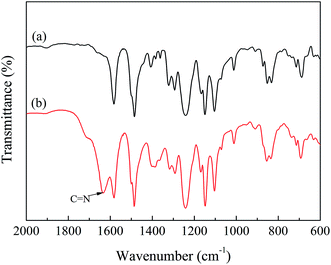
The PSF-g-P4VP polymer was prepared by ATRP using 4-vinylpyridine as the polymerizable monomer and CMPSF as the initiator, as shown in Scheme 1. The structure of the PSF-g-P4VP polymer was characterized by FTIR and 1H NMR.The FTIR spectra are presented in Fig. 1. In the spectrum of CMPSF (line (a)), several characteristic peaks were identified as follows: (i) the skeletal vibration of the benzene ring (1580 and 1478 cm−1); (ii) the asymmetric stretching of the S![[double bond, length as m-dash]](https://www.rsc.org/images/entities/char_e001.gif) O bond (1318 and 1291 cm−1); (iii) the antisymmetric vibration of C–O–C (1240 cm−1); (iv) the bending vibration of –CH3 (1382 cm−1); and a weak absorption peak characteristic of –CH2Cl (750 cm−1). In the spectrum of PSF-g-P4VP polymers (line (b)), the characteristic peak at 1634 cm−1 was attributed to the stretching vibrations of C
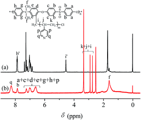
O bond (1318 and 1291 cm−1); (iii) the antisymmetric vibration of C–O–C (1240 cm−1); (iv) the bending vibration of –CH3 (1382 cm−1); and a weak absorption peak characteristic of –CH2Cl (750 cm−1). In the spectrum of PSF-g-P4VP polymers (line (b)), the characteristic peak at 1634 cm−1 was attributed to the stretching vibrations of C![[double bond, length as m-dash]](https://www.rsc.org/images/entities/char_e001.gif) N, confirming the successful polymerization of P4VP on PSF by ATRP. The chemical structures of CMPSF and PSF-g-P4VP were further characterized by 1H NMR. As shown in Fig. 2 line (a), the chemical shifts at 7.83 ppm (peak b′) and 4.53 ppm (peak i′) were ascribed to the four protons on the two phenyl rings adjacent to the sulfonyl group and the two protons of –CH2Cl, respectively. The degree of substitution (DS) was determined as the ratio between the integrated area of peaks at 4.53 ppm and 7.83 ppm in the 1H NMR spectrum.35 The DS value of the CMPSF sample was approximately 0.4, indicating that 40 –CH2Cl groups were grafted for each 100 repeat units. The 1H NMR spectra of PSF-g-P4VP are shown in Fig. 2 line (b). The peaks at 2.75 ppm (peak j) and 2.90 ppm (peak k) are ascribed to –CH2– and in the main chain of P4VP. The chemical shift at 8.25 ppm (peak q) was attributed to the two protons on the pyridine ring closest to the nitrogen atom. The bulk graft concentration or the [P4VP]/[CMPSF] molar ratio can be calculated from the 1H NMR spectrum according to the following relationship:
N, confirming the successful polymerization of P4VP on PSF by ATRP. The chemical structures of CMPSF and PSF-g-P4VP were further characterized by 1H NMR. As shown in Fig. 2 line (a), the chemical shifts at 7.83 ppm (peak b′) and 4.53 ppm (peak i′) were ascribed to the four protons on the two phenyl rings adjacent to the sulfonyl group and the two protons of –CH2Cl, respectively. The degree of substitution (DS) was determined as the ratio between the integrated area of peaks at 4.53 ppm and 7.83 ppm in the 1H NMR spectrum.35 The DS value of the CMPSF sample was approximately 0.4, indicating that 40 –CH2Cl groups were grafted for each 100 repeat units. The 1H NMR spectra of PSF-g-P4VP are shown in Fig. 2 line (b). The peaks at 2.75 ppm (peak j) and 2.90 ppm (peak k) are ascribed to –CH2– and in the main chain of P4VP. The chemical shift at 8.25 ppm (peak q) was attributed to the two protons on the pyridine ring closest to the nitrogen atom. The bulk graft concentration or the [P4VP]/[CMPSF] molar ratio can be calculated from the 1H NMR spectrum according to the following relationship:
 | (4) |
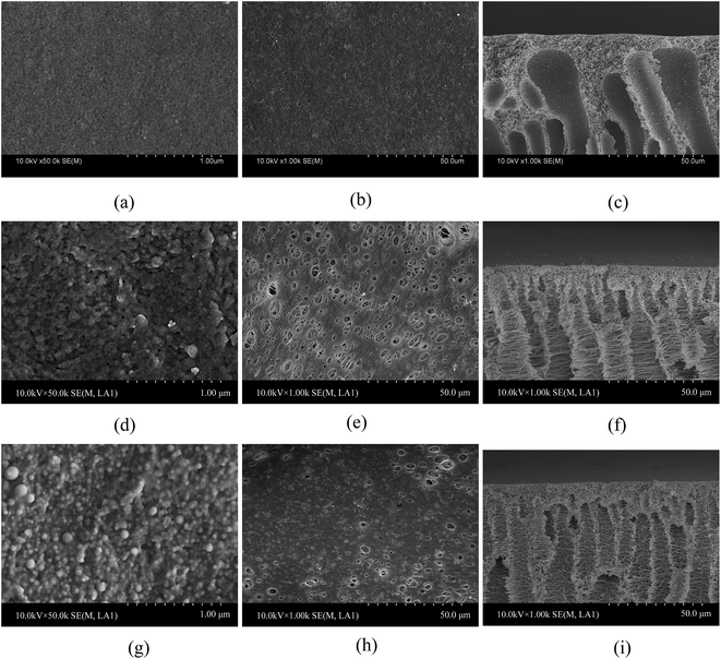
The PSF-g-P4VP blended PSF membranes were prepared by traditional phase inversion. The obtained membranes were exposed to different pH solutions for 30 min, quickly rinsed with pure water and rapidly frozen before freeze drying. The morphologies of the blended membrane and PSF blank membrane at pH 8.0 and 2.0 were obtained by FE-SEM, as shown in Fig. 3. Because the PSF blank membrane was not pH-sensitive, there was no morphology difference at pH 8.0 and 2.0. Thus, only the results at pH 8.0 are presented in Fig. 3a–c. As shown in Fig. 3a and b, the surfaces were smooth with the nanometer-sized micropores on the top surface (air side) and micron-sized holes on the bottom surface (glass side). The SEM results of the blended membrane at pH 8.0 are presented in Fig. 3d–f. Similarly, there were nanometer-sized micropores on the top surface of the blended membrane (Fig. 3d). The diameter of the pores (also micron-sized) on the bottom surface (Fig. 3e) was much larger than that of those on the blank PSF membrane (Fig. 3b). However, a very dense surface with many spherical particles could be seen on the top surface of the blended membrane at pH 2.0 (Fig. 3g), and the pore size of the bottom surface at pH 2.0 (Fig. 3h) appeared to be smaller than that at pH 8.0. Fig. 3f showed the FE-SEM image of a cross-sectional view of the PSF-g-P4VP(30)-b-PSF(70) membrane at pH 8.0. It displayed the typical asymmetric structure with a nearly dense skin layer and finger-like sublayer. The top layer included a honeycomb-like reticulated pore structure, whereas the sublayer showed a fiber-like network, which might provide good permeability. The cross-sectional view at pH 2.0 (Fig. 3i) was similar to that at pH 8.0 (Fig. 3f). The morphologies of the PSF-g-P4VP(10)-b-PSF(90) and PSF-g-P4VP(20)-b-PSF(80) membranes (not shown) were similar to that of the PSF-g-P4VP(30)-b-PSF(70) membrane.
3.2 pH-responsive permeability of the PSF-g-P4VP blended PSF membranes
P4VP provided the blended membrane with pH-responsivity and the water flux was investigated using ultrafiltration, as shown in Fig. 4. The water flux of the pristine PSF membrane was found below 10 L m−2 h−1 at 0.1 MPa (Fig. 4 line (a)), which indicated that the permeation flux of the PSF membrane was pH-independent. However, the flux of the PSF-g-P4VP blended PSF membrane was pH-dependent.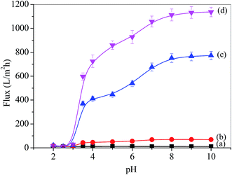 | ||
| Fig. 4 pH-dependence of water permeation through the membranes: (a) PSF, (b) PSF-g-P4VP(10)-b-PSF(90), (c) PSF-g-P4VP(20)-b-PSF(80), and (d) PSF-g-P4VP(30)-b-PSF(70). | ||
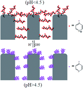
The flux increased after the PSF-g-P4VP polymer was mixed with the PSF membrane, which may be ascribed to the hydrophilic pyridine groups. The flux decreased with the increasing concentration of H+, and the most drastic decrease occurred between pH 5.0 and 3.0. The fluxes at pH = 8.0–10.0 were always higher than those at pH = 2.0–3.0, which could be due to the conformational change of the P4VP chains at the pore surface. At pH values lower than the pKa of P4VP (about 4.5), the pyridine groups were protonated and positively charged; therefore, the P4VP chains were extended due to the repulsion between positive charges, and the membrane gates were in the “closed” state (Fig. 5). Thus, the hydraulic permeability was low. However, under neutral or weakly alkaline conditions, the pyridine groups were deprotonated; therefore, the membrane gates were in the “open” state to reduce the electrostatic repulsions between the P4VP chains on the pore surfaces (Fig. 5). Consequently, the water flux dramatically increased. The abovementioned results could be described by the Hagen–Poiseuille's law,36 in which the water flux scales with the fourth power of pore diameter. As abovementioned, the pore diameter was controlled by the pH value of the solution. Therefore, the permeability was pH-dependent. Moreover, it can be seen from Fig. 4b and d that the PSF-g-P4VP blended PSF membrane with higher PSF-g-P4VP polymer content in the casting solution resulted in a higher water flux. The water flux increased from 70 to 1113 L m−2 h−1 at pH 8.0 as the content of PSF-g-P4VP in the blend membrane increased from 10% to 30%. This may be due to the increase of P4VP chains on the internal surface of the membrane pores.
To further characterize the pH-responsive performance, a coefficient, called the pH-responsive coefficient (K),37 was defined as follows:
 | (5) |
| Membrane | PSF | PSF-g-P4VP blended PSF | ||
|---|---|---|---|---|
| PSF-g-P4VP 10% | PSF-g-P4VP 20% | PSF-g-P4VP 30% | ||
| K | 1.0 | 5.1 | 38.1 | 38.5 |
The reversibility of water flux was determined by alternately switching the solution pH between 3.0 and 8.0. The results are shown in Fig. 6, where it can be seen that the permeability immediately changed and was completely reversible. The result indicated that the conformational change of P4VP is reversible.
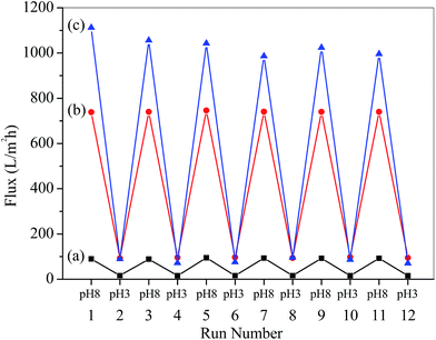 | ||
| Fig. 6 Reversible changes of water permeation through the membranes as a function of pH: (a) PSF-g-P4VP(10)-b-PSF(90), (b) PSF-g-P4VP(20)-b-PSF(80), and (c) PSF-g-P4VP(30)-b-PSF(70). | ||
3.3 Adsorption of TPPS on the PSF-g-P4VP blended PSF membrane
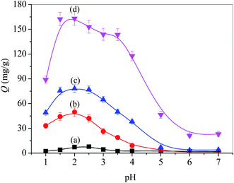
Static adsorption was performed by immersing a piece of membrane in a TPPS solution. The molecular structure of TPPS is composed of four sulfonate groups (negatively charged), whereas PSF-g-P4VP-blended PSF membrane contains blocks of P4VP, which becomes a polycation at a pH below its pKa (around 4.5).38 Thus, the electrostatic interaction between the positively charged PSF-g-P4VP-blended PSF membrane and the negatively charged TPPS depends on the pH value of the solution and may regulate the adsorption of TPPS onto the membrane.Fig. 7 shows the pH-dependent adsorption capacity (Q) of the PSF-g-P4VP-blended PSF membranes for TPPS. Thus, the adsorption capacity was relatively small when the pH of the TPPS solution was above the pKa value of the P4VP block, whereas it dramatically increased when the pH decreased from 5.0 to 3.0 and reached a peak at pH 2.0. Hence, TPPS efficiently adsorbed on the membrane surface and this was ascribed to the abovementioned typical electrostatic interaction. The adsorption capacity intensely dropped at pH 2.0–1.0. This may be due to the self-aggregation of the diacid H4TPPS2− in the solution, which was unfavorable for adsorption. In addition, it was demonstrated that the adsorption capacity increased with the increasing PSF-g-P4VP polymer content in the casting solution for the blended membranes over a wide range of pH values. In particular, the adsorption capacity increased from 50 to 163 mg g−1 at pH 2.0 as the content of PSF-g-P4VP polymer in the blend membrane increased from 10% to 30%. However, TPPS hardly absorbed on the PSF membrane since both the TPPS and PSF were electrostatically negative and likely repulsed each other. The isoelectric point of PSF is about 3.1.39 At a pH higher than 3.1, the membrane surface had an apparent negative charge due to OH− adsorption and repulsion occurs.
3.4 Rejection of TPPS
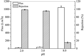
The pKa of TPPS is around 4.9,40 which is close to that of P4VP (around 4.5). At a pH lower than 4.5, TPPS and P4VP are protonated (or partially protonated). The former one tends to form aggregates, whereas the smart membrane stretches its P4VP “arms” on the surface and in the pores to capture TPPS and its aggregates via the electrostatic interactions and steric hindrance. As illustrated in Sections 3.2 and 3.3, the PSF-g-P4VP(30)-b-PSF(70) membrane showed remarkable pH-responsive permeability and a large amount of adsorption for TPPS. In this section, the retention of TPPS and its aggregates are explored.The rejection of TPPS was performed using a flow-through method. TPPS solution at a certain pH was permeated through the PSF-g-P4VP(30)-b-PSF(70) membrane. The flux and the rejection were obtained, as shown in Fig. 8. The fluxes of TPPS at pH 3.0 and 2.0 were much lower than that at pH 8.0. This is due to the closed gates of the membrane, as discussed in Section 3.2, and may also result from the retained aggregates at the gates. However, the rejection for TPPS dramatically increased at a pH below the pKa value of P4VP. Thus, the pyridine groups were protonated and positively charged at a pH value lower than 4.5 (pKa of P4VP). The large TPPS rejection is due to (1) the electrostatic adsorption between the positively charged P4VP on the membrane and the negatively charged SO3− of TPPS and (2) the rejection of the TPPS aggregates when the membrane gates were closed at low pH values. As a result, the rejection for TPPS was 99.0% at pH 2.0.
3.5 Aggregation of TPPS on the PSF-g-P4VP blended PSF membrane
In aqueous solution, the existing form of TPPS depends on the pH value.41 The monomeric free base (H2TPPS4−) translates into a zwitterionic diacid H4TPPS2− at a pH below 4.9,40 which causes changes in the UV-vis absorption spectra. As shown in Fig. 9a line (1), an intense Soret band (413 nm) and four weak Q-bands (633, 580, 552, and 515 nm) indicated the presence of the monomeric free base form of TPPS at pH 7.0. However, the Soret band shifts to 434 nm and Q-band shifts to 644 nm, illustrating the zwitterionic diacid of TPPS due to the protonation of nitrogen in the macrocycle under acid conditions (Fig. 9a, line (2) at pH 3.0, and line (5) at pH 2.0). Furthermore, a Soret band at 490 nm and a weak Q-band at 708 nm in Fig. 9a, line (6) at pH 1.0 indicated that the J-aggregates of a side-by-side type had formed due to the interaction between the positively charged center of one H2TPPS4− molecule and the negatively charged peripheral sulfonate groups of the adjacent molecules.42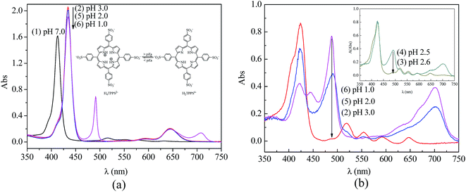 | ||
| Fig. 9 UV-vis absorption spectra of TPPS at different pH values: (a) in solution and (b) on PSF-g-P4VP(30)-b-PSF(70) membrane surface. | ||
Similarly, the type of TPPS aggregates on the membrane could be controlled by adjusting the pH value. Fig. 9b shows the UV-visible absorption spectra of TPPS on the PSF-g-P4VP(30)-b-PSF(70) membrane after the rejection experiments (Section 3.4). The TPPS were mainly in the form of a free base monomer on the blended membrane at a pH above 2.5. As shown in Fig. 9b curve (2) and curve (3), a Soret band and four Q-bands indicated the existence of the free base monomer of TPPS. The peak positions of TPPS in the aqueous solution and on the PSF-g-P4VP-b-PSF membrane surface are listed in Table 2. Note that the Soret band showed a red-shift from 413 nm to 423 nm after the TPPS in aqueous solution adsorbed on the membrane surface. In addition, TPPS was found to retain the free base monomer form on the membrane surface at pH 3.0 (<pKa of TPPS), whereas it normally forms a diacid (H4TPPS2−) in aqueous solution at the same pH value. Furthermore, a weak shoulder peak at 405 nm could be seen in Fig. 9b curves (2) and (3) at pH 3.0 and 2.6, respectively. This peak was a characteristic feature of H-dimers of the free base form43 and might result from the association of π-conjugated porphyrin rings. These type of aggregates are supposed to be H-dimers rather than H-oligomers.44 This assembly with a small aggregation number was hardly observed by SEM.
| TPPS | pH | Soret band (nm) | Q-bands (nm) |
|---|---|---|---|
| Aqueous solution | 7.0 | 413 | 515, 552, 580, 633 |
| 3.0 | 433 | 595, 644 | |
| Membrane surface | 7.0 | 423 | 519, 554, 592, 647 |
| 3.0 | 423 | 519, 554, 592, 647 |
A Soret band (488 nm) and a weak Q-band (702 nm) was observed in the Fig. 9b spectra (4) to (6), which indicated that the J-aggregated TPPS were obtained on the blended membrane at a pH below 2.5. Furthermore, the intensity of the two bands increased with the decreasing pH, suggesting that the amount of J-aggregation increased. The J-aggregation morphology on the PSF-g-P4VP(30)-b-PSF(70) membrane surface at pH 2.0 could be clearly seen in Fig. 10a. Relatively linear aggregations with a large aspect ratio, about 50–100 nm diameter and 2–5 μm length, were aligned on the blended membrane surface. For comparison, the SEM picture of the same membrane at the same pH but without TPPS is also shown in Fig. 10b.
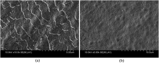 | ||
| Fig. 10 FE-SEM images of the PSF-g-P4VP(30)-b-PSF(70) membrane surface at pH 2.0 (a) with TPPS and (b) without TPPS. | ||
A summary of the conversion of the TPPS aggregation process and phase change from J-type to H-type on the PSF-g-P4VP blended PSF membrane by adjusting the pH is shown in Fig. 11.
4. Conclusion
A pH-responsive smart membrane was prepared by blending PSF-g-P4VP and PSF through the phase inversion technique. The pH response of the PSF-g-P4VP blended PSF membranes was demonstrated using hydraulic permeation results. The water flux of the blended membrane decreased with the decreasing pH value, with the most drastic decrease occurring between pH 3.0 and 5.0, and was both reversible and durable with pH switching between 3.0 and 8.0. At pH 3.0 (<pKa), the membrane pores were in a “closed” state due to the extended conformation of the P4VP chains on the pore surfaces. In contrast, at pH 8.0 (>pKa), the membrane pores were in an “open” state because of the collapsed conformation of the P4VP chains. Moreover, the flux increased with the increasing content of PSF-g-P4VP in the casting solution. The PSF-g-P4VP blended PSF membranes exhibited a considerably higher adsorption capacity for TPPS than that for the PSF alone. The adsorption capacity was strongly pH-dependent. It increased with the decrease in the pH value below the pKa of the P4VP segment and also with the increase of the PSF-g-P4VP content in the casting solution. The pH-sensitive membrane acted as a smart membrane to reject TPPS in the solution. At a pH lower than 3.0, the retention was almost 99.0%, which was ascribed to the closed gates of the membrane pores, whereas it was only 15.3% at pH 8.0 due to the opened gates of the micropores. Furthermore, the low flux and the high retention of TPPS offered a good opportunity for the self-assembly of TPPS. J-type aggregates of TPPS were observed on the PSF-g-P4VP blended PSF membrane surface after rejection at a pH below 2.5, whereas H-type aggregates were found at a pH above 2.5. The present study provides a valuable insight into the adsorption properties and aggregation behavior of TPPS on a pH-responsive porous membrane that offers a stable carrier for TPPS for use in the electronic devices and biomimetic chemistry.Conflict of interest
The authors declare no competing financial interest.Nomenclature
| Codes | Full name or meaning |
| TPPS | meso-Tetraphenylsulfonato porphyrin |
| PSF | Polysulfone |
| 4VP | 4-Vinylpyridine |
| P4VP | Poly(4-vinylpyridine) |
| PSF-g-P4VP | Polysulfone-graft-poly(4-vinylpyridine) |
| PSF-g-P4VP(10)-b-PSF(90) | PSF-g-P4VP and PSF mass ratio 1![[thin space (1/6-em)]](https://www.rsc.org/images/entities/char_2009.gif) : :![[thin space (1/6-em)]](https://www.rsc.org/images/entities/char_2009.gif) 9 9 |
| PSF-g-P4VP(20)-b-PSF(80) | PSF-g-P4VP and PSF mass ratio 2![[thin space (1/6-em)]](https://www.rsc.org/images/entities/char_2009.gif) : :![[thin space (1/6-em)]](https://www.rsc.org/images/entities/char_2009.gif) 8 8 |
| PSF-g-P4VP(30)-b-PSF(70) | PSF-g-P4VP and PSF mass ratio 3![[thin space (1/6-em)]](https://www.rsc.org/images/entities/char_2009.gif) : :![[thin space (1/6-em)]](https://www.rsc.org/images/entities/char_2009.gif) 7 7 |
| TPPS | meso-Tetraphenylsulfonato porphyrin |
| CMPSF | Chloromethylated polysulfone |
| ATRP | Atom transfer radical polymerization |
| PMDETA | N,N,N′,N′′,N′′-Pentamethyl-diethylenetriamine |
| DS | Degree of substitution |
| Jw | Water flux |
| Q | Adsorption capacity |
| K | pH-responsive coefficient |
Acknowledgements
The authors gratefully acknowledge the financial support by the National Natural Science Foundation of China (Grant No. 51303130, 51173132, 51373120, 21204064), the Changjiang Scholars and Innovative Research Team in University of Ministry of Education of China (Grant No. IRT13084), the Science and Technology Plans of Tianjin (No. 15PTSYJC00230, 14JCQNJC03900 and 15JCZDJC37600), and China Scholarship Council. The authors would like to thank Professor Georges Belfort in Rensselaer Polytechnic Institute for his assistance in preparing the manuscript.References
- M. B. M. Krishna, N. Venkatramaiah, R. Venkatesan and D. N. Rao, J. Mater. Chem., 2012, 22, 3059–3068 RSC.
- H.-J. Son, S. Jin, S. Patwardhan, S. J. Wezenberg, N. C. Jeong, M. So, C. E. Wilmer, A. A. Sarjeant, G. C. Schatz and R. Q. Snurr, J. Am. Chem. Soc., 2013, 135, 862–869 CrossRef CAS PubMed.
- M. Lv, T. Mei, C. A. Zhang and X. Wang, RSC Adv., 2014, 4, 9261–9270 RSC.
- F. D'Souza and O. Ito, Chem. Soc. Rev., 2012, 41, 86–96 RSC.
- P. Dambruoso, M. Ballestri, C. Ferroni, A. Guerrini, G. Sotgiu, G. Varchi and A. Massi, Green Chem., 2015, 17, 1907–1917 RSC.
- R. Zheng, Z. Wu, Y. Yan, J. Wang and J. Huang, RSC Adv., 2015, 5, 17253–17256 RSC.
- Y. Egawa, R. Hayashida and J.-I. Anzai, Langmuir, 2007, 23, 13146–13150 CrossRef CAS PubMed.
- A. Takahashi and S. Mukamel, J. Chem. Phys., 1995, 103, 7144–7155 CrossRef CAS.
- C. R. Jeukens, M. C. Lensen, F. J. Wijnen, J. A. Elemans, P. C. Christianen, A. E. Rowan, J. W. Gerritsen, R. J. Nolte and J. C. Maan, Nano Lett., 2004, 4, 1401–1406 CrossRef CAS.
- A. D. Schwab, D. E. Smith, B. Bond-Watts, D. E. Johnston, J. Hone, A. T. Johnson, J. C. de Paula and W. F. Smith, Nano Lett., 2004, 4, 1261–1265 CrossRef CAS.
- L. Zhang, J. Yuan and M. Liu, J. Phys. Chem. B, 2003, 107, 12768–12773 CrossRef CAS.
- A. Miura, Y. Shibata, H. Chosrowjan, N. Mataga and N. Tamai, J. Photochem. Photobiol., A, 2006, 178, 192–200 CrossRef CAS.
- L. Shen, L. Zhao, R. Qu, F. Huang, H. Gao, Y. An and L. Shi, Nano Res., 2015, 8, 491–501 CrossRef CAS.
- L. Zhao, R. Ma, J. Li, Y. Li, Y. An and L. Shi, Biomacromolecules, 2008, 9, 2601–2608 CrossRef CAS PubMed.
- Q. Zou, L. Zhang, X. Yan, A. Wang, G. Ma, J. Li, H. Möhwald and S. Mann, Angew. Chem., Int. Ed., 2014, 53, 2366–2370 CrossRef CAS PubMed.
- K. Liu, R. Xing, C. Chen, G. Shen, L. Yan, Q. Zou, G. Ma, H. Möhwald and X. Yan, Angew. Chem., 2015, 127, 510–515 CrossRef.
- A. Fateeva, P. A. Chater, C. P. Ireland, A. A. Tahir, Y. Z. Khimyak, P. V. Wiper, J. R. Darwent and M. J. Rosseinsky, Angew. Chem., 2012, 124, 7558–7562 CrossRef.
- E. Collini, C. Ferrante, R. Bozio, A. Lodi and G. Ponterini, J. Mater. Chem., 2006, 16, 1573–1578 RSC.
- Z. Liu, Y. Yi, H. Xu, X. Zhang, T. H. Ngo and M. Smet, Adv. Mater., 2010, 22, 2689–2693 CrossRef CAS PubMed.
- T. Balaji, M. Sasidharan and H. Matsunaga, Analyst, 2005, 130, 1162–1167 RSC.
- M. A. Castriciano, A. Carbone, A. Saccà, M. G. Donato, N. Micali, A. Romeo, G. De Luca and L. M. Scolaro, J. Mater. Chem., 2010, 20, 2882–2886 RSC.
- M. Li, L. Zhao, Y. Zhang, M. Liu, H. Ye, Y. Zhang and X. Chen, Colloid Polym. Sci., 2015, 293, 513–522 CAS.
- L. Zhao, M. Liu, S. Li, A. Li, H. An, H. Ye and Y. Zhang, J. Mater. Chem. C, 2015, 3, 3650–3658 RSC.
- M. Liu, L. Zhao, S. Li, H. Ye, H. An and Y. Zhang, RSC Adv., 2016, 6, 10704–10712 RSC.
- T. Yamaguchi, T. Ito, T. Sato, T. Shinbo and S.-I. Nakao, J. Am. Chem. Soc., 1999, 121, 4078–4079 CrossRef CAS.
- M. Wang, Q.-F. An, L.-G. Wu, J.-X. Mo and C.-J. Gao, J. Membr. Sci., 2007, 287, 257–263 CrossRef CAS.
- Z. Zhang, X. Zhu, F. Xu, K. Neoh and E. Kang, J. Membr. Sci., 2009, 342, 300–306 CrossRef CAS.
- C. Zhao, S. Nie, M. Tang and S. Sun, Prog. Polym. Sci., 2011, 36, 1499–1520 CrossRef CAS.
- A. M. Mika, R. F. Childs and J. M. Dickson, J. Membr. Sci., 2002, 206, 19–30 CrossRef CAS.
- B. Yang and W. Yang, J. Membr. Sci., 2005, 258, 133–139 CrossRef CAS.
- M. Wang, Y. Ji, Y. Zhang, S. Wang, X. Long, L. Zhao and F. Yan, Polym. Mater. Sci. Eng., 2016, 32(3), 64–69 CAS.
- C. A. Steinbeck, M. Ernst, B. H. Meier and B. F. Chmelka, J. Phys. Chem. C, 2008, 112, 2565–2573 CAS.
- S. Jiang and M. Liu, J. Phys. Chem. B, 2004, 108, 2880–2884 CrossRef CAS.
- L. Li, G. Yan and J. Wu, J. Appl. Polym. Sci., 2009, 111, 1942–1946 CrossRef CAS.
- F. Yan, H. Pei, Y. Pei, T. Li, J. Li, B. He, Y. Cheng, Z. Cui, D. Guo and J. Cui, Ind. Eng. Chem. Res., 2015, 54, 3473–3479 CrossRef.
- Y. M. Lee and J. K. Shim, Polymer, 1997, 38, 1227–1232 CrossRef CAS.
- T. Luo, S. Lin, R. Xie, X.-J. Ju, Z. Liu, W. Wang, C.-L. Mou, C. Zhao, Q. Chen and L.-Y. Chu, J. Membr. Sci., 2014, 450, 162–173 CrossRef CAS.
- S. N. Sidorov, L. M. Bronstein, Y. A. Kabachii, P. M. Valetsky, P. L. Soo, D. Maysinger and A. Eisenberg, Langmuir, 2004, 20, 3543–3550 CrossRef CAS PubMed.
- M. Pontié, X. Chasseray, D. Lemordant and J. Lainé, J. Membr. Sci., 1997, 129, 125–133 CrossRef.
- G. De Luca, A. Romeo and L. M. Scolaro, J. Phys. Chem. B, 2006, 110, 7309–7315 CrossRef CAS PubMed.
- L. Zhao, X. Wang, Y. Li, R. Ma, Y. An and L. Shi, Macromolecules, 2009, 42, 6253–6260 CrossRef CAS.
- J. M. Ribó, R. Rubires, Z. El-Hachemi, J.-A. Farrera, L. Campos, G. L. Pakhomov and M. Vendrell, Mater. Sci. Eng., C, 2000, 11, 107–115 CrossRef.
- N. C. Maiti, S. Mazumdar and N. Periasamy, J. Phys. Chem. B, 1998, 102, 1528–1538 CrossRef CAS.
- P. Kubát, K. Lang, P. Janda and P. Anzenbacher, Langmuir, 2005, 21, 9714–9720 CrossRef PubMed.
| This journal is © The Royal Society of Chemistry 2017 |


