
 Open Access Article
 This Open Access Article is licensed under a
 Creative Commons Attribution 3.0 Unported Licence
Mille-feuille shaped hard carbons derived from polyvinylpyrrolidone via environmentally friendly electrostatic spinning for sodium ion battery anodes
Ying Bai *ab,
Yuanchang Liua,
Yu Lia,
Liming Linga,
Feng Wuab and
Chuan Wuab
*ab,
Yuanchang Liua,
Yu Lia,
Liming Linga,
Feng Wuab and
Chuan Wuab
aBeijing Key Laboratory of Environmental Science and Engineering, School of Materials Science and Engineering, Beijing Institute of Technology, Beijing 100081, PR China. E-mail: membrane@bit.edu.cn
bCollaborative Innovation Center of Electric Vehicles in Beijing, Beijing 100081, PR China
First published on 17th January 2017
Abstract
Pursuing low-cost and high-performance anode materials is of great importance for developing practical sodium ion batteries. In this work, mille-feuille shaped hard carbons derived from low-cost and environmentally friendly polyvinylpyrrolidone (PVP) nanofibres are fabricated via simple electrostatic spinning and followed by further pyrolysis at 800–1200 °C, as anode materials for sodium ion batteries. The optimized sample HC-1000 carbonized at 1000 °C shows better particle size and low surface area, and achieves a good reversible capacity of 271 mA h g−1 with 94% capacity retention ratio over 100 cycles. In addition, HC-1000 exhibits satisfactory rate performance, namely, the discharge capacities are 304, 264, 209, 142, 109 and 70 mA h g−1 at a current density of 20, 40, 100, 200, 500 and 1000 mA g−1 after 10 cycles respectively. Even continuing with an additional 280 cycles at 200 mA g−1, the capacity retains 285 mA h g−1 when the current recovers to 20 mA g−1. The mille-feuille shaped morphology, uniform particle size distribution and low surface area enable excellent electrochemical performances of PVP based hard carbon, which is expected to be a promising anode material for Na-ion batteries.
Introduction
The storage and transformation of energy have become an important problem which restricts the sustainable development of the world economy.1,2 Lithium ion batteries are the first choice for electric vehicles (including HEV and EV) and power supply for large-scale energy storage systems with the advantages of high working voltage, high capacity, small self-discharge, long cycle life and so on.3,4 However, with the development of renewable energy generation technology, a large number of energy storage batteries are needed. However, the global lithium resources are not able to effectively meet the huge demand, due to the limitation of lithium resources. Therefore, it is very important to develop the related energy storage technology as a substitute for lithium ion batteries.1,5–8 Recently, sodium ion batteries have attracted renewed interest as a potentially lower cost alternative to lithium ion batteries because of the wide abundance of sodium resources and similar chemical properties between lithium and sodium. But the Na ion is about 55% larger than the Li ion, it is difficult to develop suitable host materials with sufficiently large interstitial space to allow rapid insertion/extraction of Na+. Moreover, the standard electrode potential of Na+/Na is −2.71 V (vs. S.H.E.), which is about 0.3 V higher than that of Li+/Li. Therefore, the energy density of the sodium ion battery is lower than that of lithium ion battery.9–12 However, they can be considered for use in applications where the weight and footprint requirement is less drastic, such as storage of off-peak and essentially fluctuating renewable energies.13Over the past few years, there has been made significant progress for sodium ion battery cathodes by updating the knowledge learned from lithium ion battery studies.8,14–17 With respect to anodes, the graphite has been widely used in lithium ion battery, while the radius of the sodium is much larger so that the graphite carbon layer spacing (0.335 nm) is not suitable for the insertion of sodium ions, which were reported in previous studies.18,19 But three-dimensional porous graphene materials facilitates significant performance for Na-ion batteries in recent research.20 The other promising anode electrode materials mainly include alloys, carbon based materials, organic compounds and Ti-based oxides.19,21–23 Of the above candidates, carbon-based material is a promising material as they are cheap, easily stable and non-toxic. As one kind of disorder carbon with larger layer spacing (0.35–0.38 nm) hard carbon has been widely studied.24–35 Doeff24 et al. showed the hard carbon can be a potential anode material in 1993. They studied the electrochemical insertion of sodium ion into a hard carbon made from petroleum coke, achieving a reversible capacity of 85 mA h g−1. Komaba's group28 reported a reversible capacity value of 240 mA h g−1 by using commercially available hard carbon.
Generally hard carbon as one kind of disordered carbon has a widely dispersed particle size and a different morphology, which depend on appropriate carbon source and precursor morphology.24–32 Shu et al.30 obtained nano-sized hard carbon spherules by well dispersed nano-sized precursor particles during hydrothermal reaction, which showed high capacity retention ratio (92.7%) and a high reversible charge capacity (525 mA h g−1) in lithium ion batteries. Li et al.31 fabricated monodispersed hard carbon spherules with a uniform particle size, which exhibited highly reversible capacity of 290 mA h g−1 (after 100 cycles at 30 mA g−1), corresponding to capacity retention 93% in sodium ion batteries. Liu et al.32 prepared floral variant of mesoporous carbon achieved excellent performance in sodium ion batteries (438.5 mA h g−1 at 30 mA g−1) and lithium ion batteries (1370 mA h g−1 at 50 mA g−1). And sodium ion full cell was reported with a layered NaNi0.5Ti0.5O2 cathode and a hard carbon anode exhibiting a reversible capacity of 93 mA h g−1.33
Electrospinning has been used widely in both academic research and industrial applications as a simple and versatile technique. Polyacrylonitrile (PAN), polyvinyl chloride (PVC) and polyvinylpyrrolidone (PVP) are widely used in electrospinning to make uniform nanofibers/hollow nanowires.34–37 In our previous work,34 hard carbon prepared through pyrolysis of PVC nanofibers can achieve an initial reversible capacity of 271 mA h g−1 and retain 215 mA h g−1 after 120 cycles at the current of 12 mA g−1. Chen36 et al. reported a carbon nanofibers prepared by carbonization–activation PAN nanofibers using electrospun PAN fibers, which delivered a reversible capacity as high as 233 mA h g−1 and excellent cycling stability over 50 cycles at the current of 50 mA g−1.
However, during the process of pyrolysis, PAN produces hydrogen cyanide (HCN) gas which is toxic and harmful to environment.38 And hydrogen chloride and benzene are the main products of PVC.39 But it is found that the vinyl pyrrolidone is the main volatile products of the pyrolysis of PVP that is less toxic and environmental friendly.40 (Scheme 1).
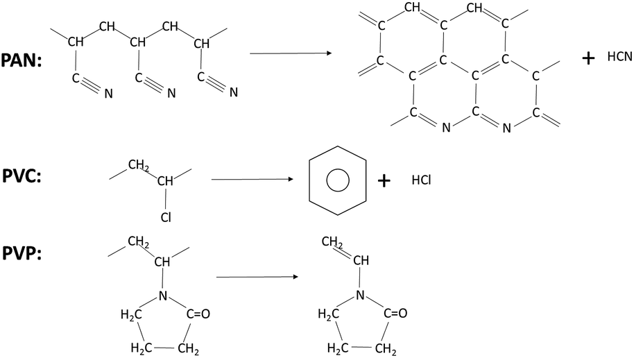 | ||
| Scheme 1 The main products of PAN, PVC and PVP in pyrolysis process. | ||
Furthermore, as we know, the solubility parameter (δ) provides a good indication of solubility. Materials with similar values of δ are likely to be miscible; and the solubility parameters41 of the materials are shown in Table 1. According to this parameter, it is notable that the solubility of PVP in N,N-dimethylformamide (DMF) is better than that of PAN and PVC, which suggests we can obtain a more homogeneous electrospinning solution and achieve a more uniform precursor if dissolving PVP in DMF.
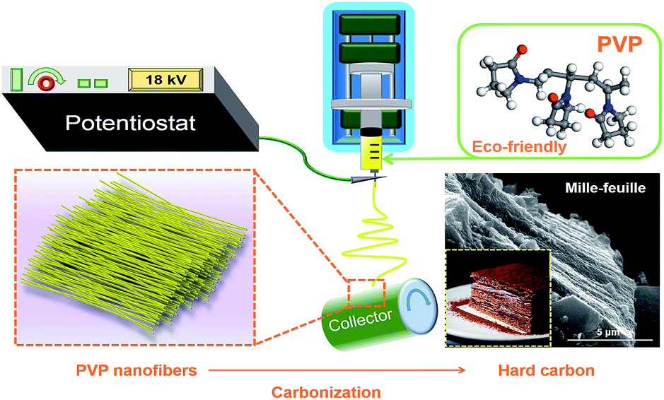
In this work, we chose the PVP as the solute in DMF to prepare the electrospinning solution to get the hard carbon. The uniform nanofibers were prepared by electrospinning and mille-feuille shaped hard carbon material with a good particle size and low surface area was prepared after high temperature pyrolysis. Thus hard carbon by electrospinning with PVP as carbon source delivered satisfactory electrochemical performances.
Experimental
Synthesis of hard carbon
Typically, 3 g polyvinylpyrrolidone (average Mw 1![[thin space (1/6-em)]](https://www.rsc.org/images/entities/char_2009.gif) 300000 Aldrich) was dissolved in 20 mL N,N-dimethylformamide to form a 15 w/v% solution by stirring at 40 °C to be prepared as the electrospun solution. Then, the polymer solution was loaded into a 10 mL syringe which connected to a blunt tip needle. The needle tip was placed 15 cm in the front of the collector. Two high voltages of 14 kV and −4.00 kV were applied to them, respectively. A syringe pump pushed the syringes at a flow rate of 1 mL h−1. Al foil was used to cover the collector to collect nanofiber. The fibers were peeled off and dried in vacuum at 80 °C overnight. Thereafter, the fibers were carbonized at 800, 900, 1000, 1100 and 1200 °C for 2.5 h, respectively, with a heating rate of 3 °C min−1, as shown in Scheme 2. The atmosphere in the tube furnace was argon with a flow rate of 200 cm3 min−1. The hard carbon (HC) samples were denoted as HC-800, HC-900, HC-1000, HC-1100 and HC-1200, respectively. For comparison, hard carbon was prepared by direct pyrolysis of commercial PVP at 1000 °C, named as CP-1000. The yield of hard carbon from PVP is about 6%.
300000 Aldrich) was dissolved in 20 mL N,N-dimethylformamide to form a 15 w/v% solution by stirring at 40 °C to be prepared as the electrospun solution. Then, the polymer solution was loaded into a 10 mL syringe which connected to a blunt tip needle. The needle tip was placed 15 cm in the front of the collector. Two high voltages of 14 kV and −4.00 kV were applied to them, respectively. A syringe pump pushed the syringes at a flow rate of 1 mL h−1. Al foil was used to cover the collector to collect nanofiber. The fibers were peeled off and dried in vacuum at 80 °C overnight. Thereafter, the fibers were carbonized at 800, 900, 1000, 1100 and 1200 °C for 2.5 h, respectively, with a heating rate of 3 °C min−1, as shown in Scheme 2. The atmosphere in the tube furnace was argon with a flow rate of 200 cm3 min−1. The hard carbon (HC) samples were denoted as HC-800, HC-900, HC-1000, HC-1100 and HC-1200, respectively. For comparison, hard carbon was prepared by direct pyrolysis of commercial PVP at 1000 °C, named as CP-1000. The yield of hard carbon from PVP is about 6%.
 | ||
| Scheme 2 Schematic illustration of the synthesis process for the mille-feuille shaped hard carbons derived from PVP. | ||
Characterizations
X-ray diffractometer (Rigaku DMAX2400) with Cu-Kα radiations was used to characterize the structures of the samples in the 2θ range 10° to 80°. The interlayer distance d002 were calculated by the Bragg equations with XRD spectra. JSM-35C scanning electron microscope and HITACHI H-800 transmission electron microscope were used to observe the morphologies of the samples. LS-POP(9) laser scattering particle analyzer was used to analyse the particle size distribution of the materials. Carbon dioxide adsorption isotherms were determined by carbon dioxide physisorption at 273 K on a Micromeritics ASAP 2020 analyzer.Electrochemical measurements
The working electrode was prepared by mixing hard carbon powder, acetylene black and polyvinylidene fluoride (PVDF) at a weight ratio of 8:1:1 and coated on a copper foil collector. The loading mass of hard carbon electrode was 0.45 mg cm−2. The coin-type cells were assembled in an Ar-filled glovebox (MBRAUN-6020) under an argon atmosphere with oxygen and water of less than 0.5 ppm. The electrolyte was a solution of 1 M NaClO4 in a solvent of propylene carbonate (PC) (Shenzhen Capchem technology Co., Ltd., China). The amount of electrolyte is about 0.2 mL in a coin cell. The counter electrode was sodium foil. The separator was the glass fiber. The galvanostatic cycling conducted with LAND-CT2011A battery tester at the current density of 20 mA g−1 at a voltage interval of 0.01–2.5 V. Cyclic voltammograms (CV) were carried out by CHI608E electrochemical workstation at a scan rate of 0.1 mV s−1. Electrochemical impedance spectroscopy (EIS) measurements were conducted in the frequency range of 0.01 Hz to 10 kHz.
Results and discussion
Fig. 1a shows the apparent morphologies of the PVP fibers from the scanning electron microscopy (SEM). The nanofibers display homogeneous length, interconnected and continuous fibrous morphology. The hard carbon particle shows an irregular shape with sharp edge in macroscopic (Fig. 1b–f). In this work, when samples were calcined from 800 °C to 1000 °C, the particle size decreases with increasing pyrolysis temperature due to the polymer main chain breaking down to monomer; when the temperature increases from 1000 °C to 1200 °C, the particle size increases again for the agglomeration with the formation of oligomer.40 Therefore, HC-1000 shows the smallest particle size in the samples.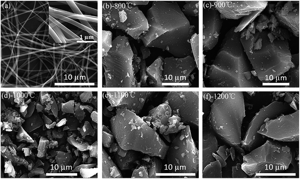 | ||
| Fig. 1 SEM images of PVP precursors and as-prepared samples at different temperature (a) PVP nanofibers prepared by electrospinning (b) HC-800 (c) HC-900 (d) HC-1000 (e) HC-1100 (f) HC-1200. | ||
In Fig. 2a, the morphology of HC-1000 exhibits the stacking of thin slice as a mille-feuille even though the sample was ground, which is in favor of facile electrolyte permeation and rapid Na+ diffusion. Whereas, CP-1000 particle without electrospinning only shows some wrinkles on its surface and an irregular morphology, as shown in Fig. 2b. It is obvious that the unique morphology of HC-1000 is originated from electrospinning and still keeps a mille-feuille shape well after grinding.
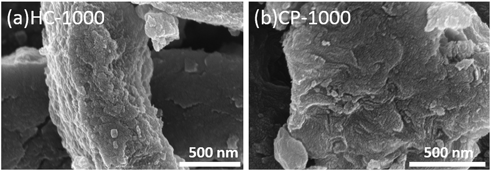 | ||
| Fig. 2 SEM images of hard carbon particle after grinding (a) HC-1000 (b) CP-1000. | ||
TEM pictures of the samples are shown in Fig. 3. Graphene layers with random orientation could be observed in the samples. The graphene domains tend to orient with the increasing temperature, because graphitization degree increases from 800 °C to 1200 °C.25 CP-1000 shows more obvious graphitization than HC-1000, indicating the electrospinning could reduce the graphitization.34,35
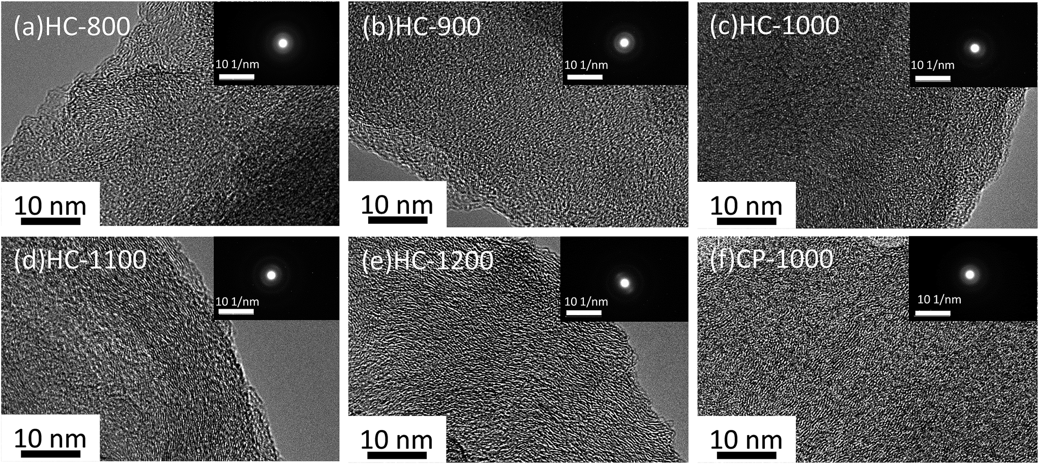 | ||
| Fig. 3 TEM images of hard carbon particle (a) HC-800 (b) HC-900 (c) HC-1000 (d) HC-1100 (e) HC-1200 (f) CP-1000. The insets show the selected area electron diffraction of corresponding samples. | ||
From the particle distribution in Fig. 4a, the particle size of HC-1000 is the smallest, showing a peak at around 8 μm and all particles exhibit smaller than 20 μm. The other four samples show a centralized distribution at around 18 μm and particle sizes are from 0 to 100 μm. The small and uniform particle of HC-1000 is suitable to shorten the Na+ diffusion path and achieve low impedance, which contributes to the rapid Na+ insertion/extraction and enables the materials to exhibit excellent electrochemical performances.30,42–44
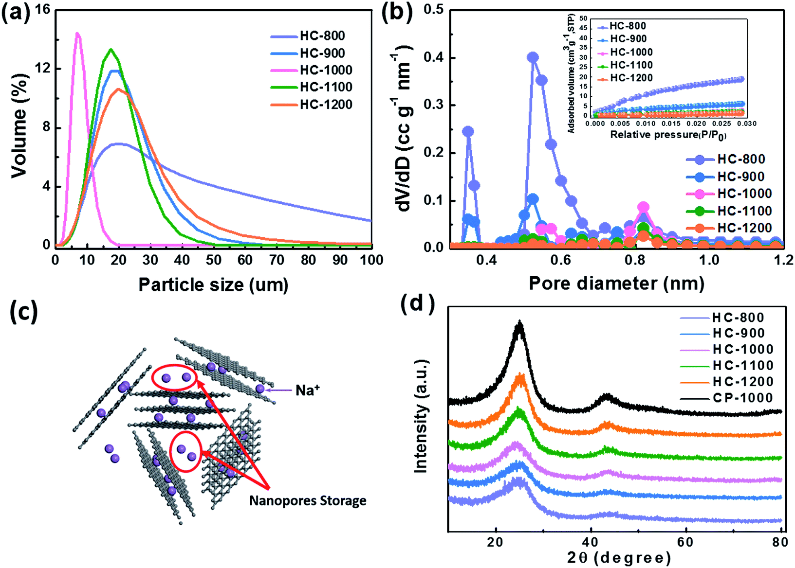 | ||
| Fig. 4 (a) The particle size distribution of the materials. (b) The pore size distribution and carbon dioxide adsorption isotherms in the inset. (c) Schematic representation of Na ion storage mechanisms in hard carbon (d) XRD patterns of different hard carbon samples. | ||
As shown in Fig. 4b, HC exhibits a BET surface area of 184, 63, 27, 21 and 12 m2 g−1 at the pyrolysis temperature of 800, 900, 1000, 1100 and 1200 °C, respectively. HC-800 and HC-900 show larger pore volume and surface area than the others, which would lead a serious decomposition of the electrolyte.45,46 The micropore volume decreases with the increasing temperature from 800 to 1200 °C (Table 2), because the growth of graphene domains leads to the closure of micropores in the sample.37,47 These nanopores surrounded by randomly stacked graphene sheets are supposed to contribute to a main Na+ storage at around 0 V,24,28,48 which cannot be detected by CO2 adsorption analysis, as shown in Fig. 4c.
| Sample | Pyrolysis temperature (°C) | 2θ/° | d002/nm | SBET/m2 g−1 | Vtotal/cm3 g−1 |
|---|---|---|---|---|---|
| HC-800 | 800 °C | 24.46 | 0.364 | 184 | 0.055 |
| HC-900 | 900 °C | 24.32 | 0.366 | 63 | 0.02 |
| HC-1000 | 1000 °C | 23.48 | 0.378 | 27 | 0.01 |
| HC-1100 | 1100 °C | 24.02 | 0.370 | 21 | 0.008 |
| HC-1200 | 1200 °C | 24.26 | 0.368 | 12 | 0.005 |
| CP-1000 | 1000 °C | 25.02 | 0.356 | — | — |
The XRD patterns of hard carbon at different temperature are shown in Fig. 4d. All the hard carbon samples at different temperature exhibit a typical amorphous carbon structure. Two broad peaks, namely, (002) and (101) diffractions, are observed in the XRD patterns. As shown in Table 2, the distance of interlayer (d002) is larger than that of graphite (0.335 nm) according to the calculation results, which is favorable for sodium ion storage and transport. Additionally, it also indicates that the temperature is a significant factor affecting the interlayer space during the synthetic process. The calculated interlayer distance increases gradually with the carbonized temperature increasing from 800 °C to 1000 °C. However, when carbonized temperature further increases to 1100 °C and 1200 °C, the d002 values decrease, because the graphitization makes some narrow interlayer spacing close to graphite.26 The interlayer space of HC-1000 is also lager than CP-1000 with only 0.356 nm because the nanofiber precursor achieves a lower graphitization during the pyrolysis process than the bulk without electrospinning, which is in agreement with XRD results.34,35 Sample HC-1000 shows a highest value of d002, which means that this material can accommodate more sodium ions storage and faster Na+ transport kinetics.36,37
Fig. 5a–e show the 1st, 2nd and 20th discharge–charge profiles of the HC-800, HC-900, HC-1000, CP-1000, HC-1100 and HC-1200 electrodes, respectively. The low initial coulombic efficiency is likely from the formation of SEI film and Na+ being trapped into the some voids and cavity sites or vicinity of residual heteroatoms.36 The profiles can be divided into two regions with a slope from 1.0 to 0.1 V and a plateau close to 0 V. According to previous studies,28,37,49 the sloping voltage profile above 0.1 V corresponds to sodium insertion between graphene layers. The plateau close to 0 V results from the sodium ions insertion into nanopores.
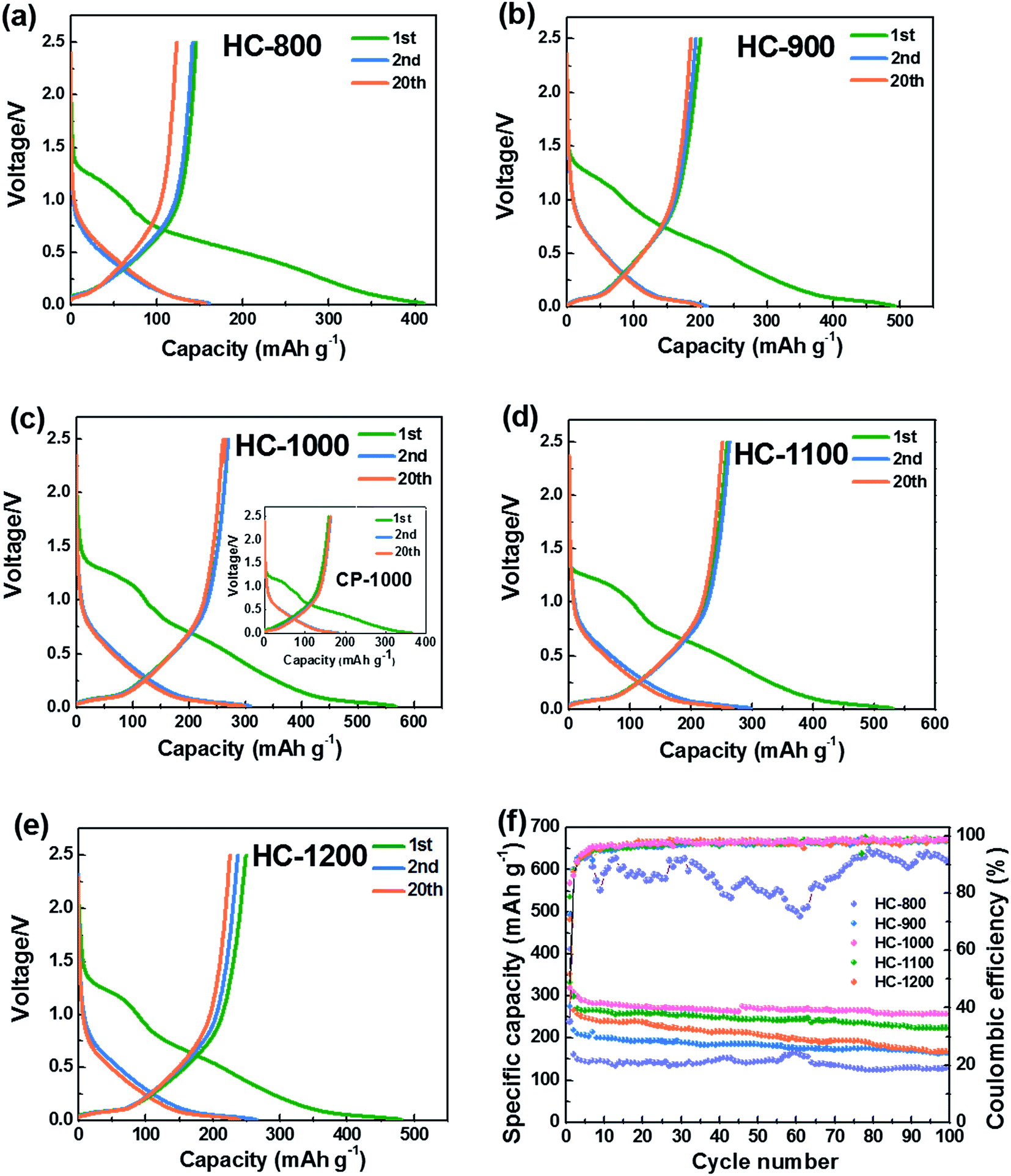 | ||
| Fig. 5 Discharge–charge profiles of hard carbons at 20 mA g−1 (a) HC-800 (b) HC-900 (c) HC-1000 and CP-1000 (d) HC-1100, and (e) HC-1200, (f) cycling performance of HC electrodes tested at 20 mA g−1, the voltage range is between 0.01 and 2.5 V. | ||
Fig. 5f shows the cycling performance of the HC electrodes and CP-1000 electrode at 20 mA g−1. When calcined at 800 °C, the as-obtained material exhibits a low reversible capacity and is not stable in the subsequent cycles because of incomplete carbonization and serious decomposition of the electrolyte caused by large surface area. The reversible capacities of HCs increase with increasing carbonization temperature from 800 to 1000 °C. Whereas, the reversible capacity decreases when the carbonization temperature exceeds 1000 °C. This phenomenon can be explained by the largest interlayer spacing and appropriate structure of HC-1000, which is more favorable for sodium ion storage and transport.27,36 The sample HC-1000 delivers superior electrochemical performances, initial discharge and charge capacities are 568 and 271 mA h g−1, respectively. CP-1000 only shows an initial discharge and charge capacities of 382 and 158 mA h g−1 because of a low interlayer spacing caused by higher graphitization degree. HC-1000 retains a reversible capacity of 255 mA h g−1 after 100 cycles, corresponding to excellent capacity retention of 94%. In contrast, the HC-800, HC-900, HC-1100 and HC-1200 electrodes exhibit inferior reversible capacities: about 119 mA h g−1, 160 mA h g−1, 220 mA h g−1 and 166 mA h g−1 remained after 100 cycles, respectively, with capacity retention of 82%, 80%, 84% and 69%. For the sample HC-1000, the coulombic efficiency after the 100 cycles remains approximately 99%, indicating hard carbon from PVP is very suitable as an anode for Na-ion batteries.
The cyclic voltammogram (CV) curves of HC-1000 can be seen in Fig. 6a. In the first cycle, two distinct reduction peaks at 0.89 V and 0.27 V can be observed, which are related to the decompositions of the solvent and electrolyte salt to form the SEI.50 In the second and subsequent cycles, the reduction peaks at 0.89 V and 0.27 V disappear, which indicates that the irreversible reaction of the formation of SEI film is mainly accomplished in the initial cycle.51 The broad reduction peak at 0.5 V corresponds to the insertion of sodium ions in the graphene layers. A pair of sharp redox peaks in the low potential region below 0.2 V are ascribed to Na+ insertion–extraction in the nanopores of the hard carbon.52,53 The well overlapped CV curves indicate a satisfactory capacity retention of HC-1000 after the initial capacity loss.
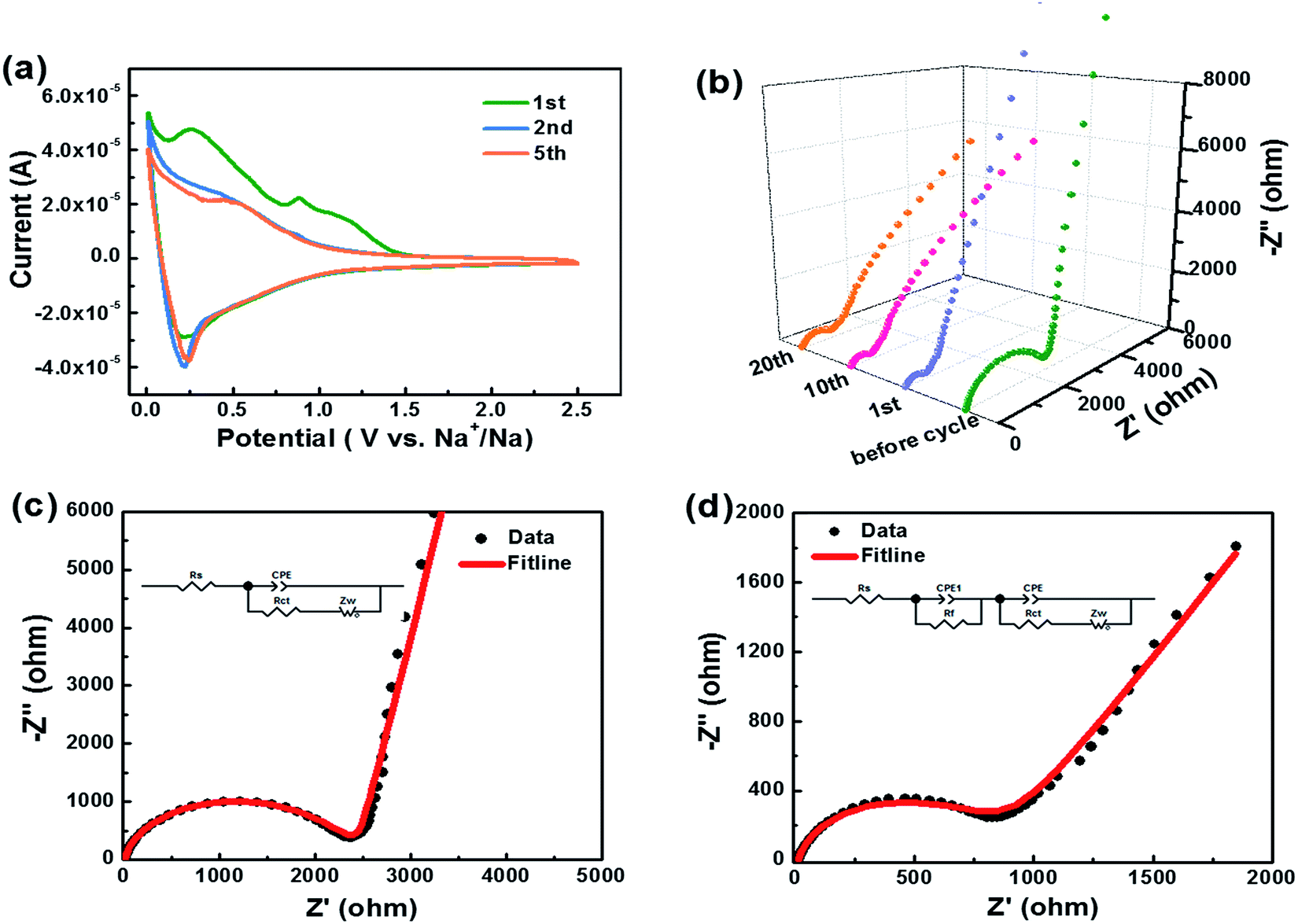 | ||
| Fig. 6 (a) Cyclic voltammogram curves of sample HC-1000 at a scan rate of 0.1 mV s−1 between 0.01 and 2.5 V. (b) Nyquist plot deduced from EIS measurements of as prepared cells before cycle, after 1st, 10th and 20th cycle. (c) The fitline of Nyquist plot and equivalent circuit used to fit the EIS of sample HC-1000 before cycle and (d) after 20th cycle. | ||
Kinetic information of HC-1000 electrode during cycling is acquired by EIS measurements (Fig. 6b). The Nyquist plots are fitted and interpreted well based on the equivalent electric circuit54,55 (Fig. 6c and d). Rs is the internal resistance of cell and has no obvious change after 20 cycles, as the fitting results of the equivalent circuit listed in Table 3. In the initial cycle, the large semicircle is related to charge transfer resistance (Rct) and constant phase element (CPE),36,56 which consists of another small high-frequency semicircle stemmed from Rf and CPE1 ascribed to the SEI layer after first cycle. Zw is Warburg impedance. And a sloping straight line in the low frequency range is attributed to the mass-transfer process. Because the wettability between nonpolar carbon material and the polar liquid electrolyte is not good enough,57 the electrode shows a transfer resistance of 2180 Ω before cycle. However, the Rct decreases obviously (Fig. 6b) after the first cycle for the wetting process between the electrode material and the liquid electrolyte. And the transfer resistance tends to be stable in the next cycle with about 720.2 Ω after 20 cycles.
| Before cycle | 20th cycle | ||
|---|---|---|---|
| Rs (Ω) | 6.9 | 7.2 | |
| Rf (Ω) | — | 84.6 | |
| CPE1 | T (Ω−1 sn) | — | 0.012 |
| P | — | 0.89 | |
| Rct (Ω) | 2180 | 720.2 | |
| CPE | T (Ω−1 sn) | 2.13 × 10⁻⁶ | 4.3 × 10⁻⁶ |
| P | 0.92 | 0.85 | |
| Zw | R (Ω) | 792 | 735 |
| τ (s) | 0.25 | 0.12 | |
| P | 0.45 | 0.34 |
The sodium ion diffusion (DNa+) in HC-1000 electrode can be calculated from the plots in the low-frequency region, and the equation can be expressed as:58,59
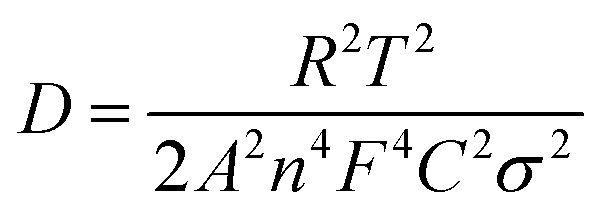 | (1) |
| Zre = Re + Rct + σω−1/2 | (2) |
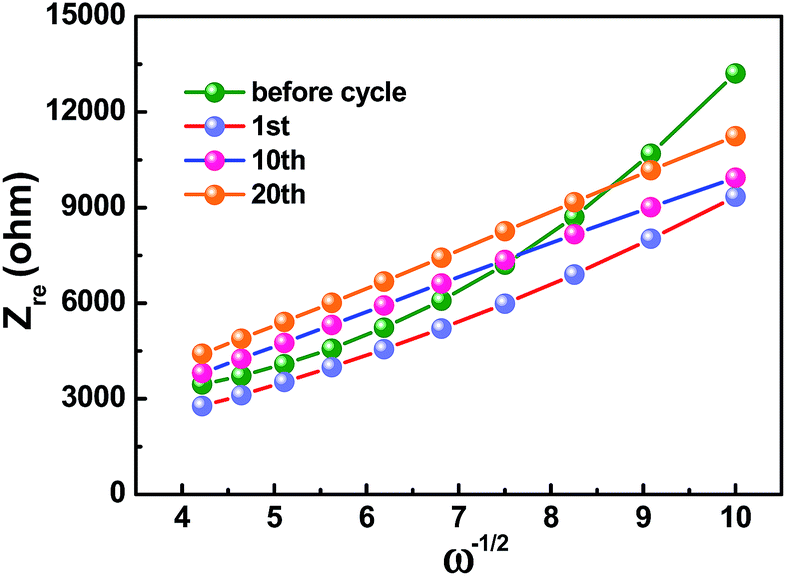 | ||
| Fig. 7 The relationship between Zre and ω−1/2 at low frequencies of HC-1000 electrode. | ||
| Before cycle | 1st cycle | 10th cycle | 20th cycle | |
|---|---|---|---|---|
| D (cm2 s−1) | 4.83 × 10⁻¹⁴ | 1.14 × 10⁻¹³ | 1.21 × 10⁻¹³ | 1.08 × 10⁻¹³ |
The rate performance of the HC-1000 electrode is observed as showed in Fig. 8. At current densities of 20, 40, 100, 200, 500 and 1000 mA g−1 after 10 cycles, the discharge capacities of 304, 264, 209, 142, 109 and 70 mA h g−1 can be achieved. Furthermore, with additional 280 cycles at current density of 200 mA g−1, namely, from the 70th to the 350th cycles, an average coulombic efficiency of 99.7% is delivered. When the current density returns to 20 mA g−1, the capacity can recover to 285 mA h g−1. It can be observed that the sharp edge of hard carbon becomes smooth because of a homogeneous SEI coverage but the particle has no obvious pulverization after 360 cycles, indicating that the structure of hard carbon is not damaged. The HC-1000 electrode exhibits excellent rate capability and cycle stability, which is ascribed to the mille-feuille shaped morphology, uniform particle size, large interlayer distance and appropriate structure with porous channel for facile electrolyte permeation and rapid Na+ insertion/extraction.
 | ||
| Fig. 8 Discharge capacities of HC-1000 at different current densities of 20, 40, 100, 200, 500 and 1000 mA g−1, respectively. A long-term cycling performance is recorded from the 70th to the 350th cycles at 200 mA g−1 and SEM images of the HC-1000 electrodes before and after 360 cycles. | ||
Conclusions
Hard carbons originated from PVP are successfully prepared by environmentally friendly electrospinning combined with subsequent carbonization. And according to the “like dissolves like” principle, PVP has superior dissolubility in DMF solvent, and thus results in uniform nanofiber precursor. The hard carbons as-prepared show a mille-feuille shaped morphology. Among all these samples, the optimized sample HC-1000 with a carbonization temperature of 1000 °C exhibits a uniform and the smallest particle distribution at around 8 μm and the largest interlayer distance of 0.378 nm, which are beneficial to shorten the Na+ diffusion path and achieve low impedance and fast Na+ diffusion. At a current of 20 mA g−1, initial reversible capacity of HC-1000 is 271 mA h g−1, which retains 255 mA h g−1 after 100 cycles, corresponding to excellent capacity retention of 94%. At a high current of 1000 mA g−1, it still remains a reversible capacity of 70 mA h g−1. It is notable that even after an additional 280 cycles at current density of 200 mA g−1, an average coulombic efficiency of 99.7% is observed, and a high reversible capacity of 285 mA h g−1 can still be achieved when the current density back to 20 mA g−1. The superior electrochemical performances are attributed to the mille-feuille shaped morphology, uniform particle size, large interlayer distance and appropriate structure with porous channel for facile electrolyte permeation and rapid Na+ insertion/extraction.Acknowledgements
The present work is supported by the National Basic Research Program of China (Grant No. 2015CB251100), the Program for New Century Excellent Talents in University (Grant No. NCET-13-0033), and the Beijing Co-construction Project (Grant No. 20150939014).Notes and references
- X. Lu, G. Xia, J. P. Lemmon and Z. Yang, J. Power Sources, 2010, 195, 2431–2442 CrossRef CAS.
- J. M. Tarascon and M. Armand, Nature, 2001, 414, 359–367 CrossRef CAS PubMed.
- X. L. Wu, L. Y. Jiang, F. F. Cao, Y. G. Guo and L. J. Wan, Adv. Mater., 2009, 21, 2710–2714 CrossRef CAS.
- H. G. Jung, M. W. Jang, J. Hassoun, Y. K. Sun and B. A. Scrosati, Nat. Commun., 2011, 2, 516 CrossRef PubMed.
- C. Wadia, P. Albertus and V. Srinivasan, J. Power Sources, 2011, 196, 1593–1598 CrossRef CAS.
- G. Ceder, G. Hautier, A. Jain and S. P. Ong, MRS Bull., 2011, 36, 185–191 CAS.
- B. L. Ellis, W. R. M. Makahnouk, Y. Makimura, K. Toghill and L. F. Nazar, Nat. Mater., 2007, 6, 749–753 CrossRef CAS PubMed.
- Y. Bai, L. X. Zhao, C. Wu, H. Li, Y. Li and F. Wu, ACS Appl. Mater. Interfaces, 2016, 8, 2857–2865 CAS.
- Y. Naoaki, K. Kei, D. Mouad and K. Shinichi, Chem. Rev., 2014, 114, 11636–11682 CrossRef PubMed.
- H. Li, C. Wu, F. Wu and Y. Bai, Acta Chim. Sin., 2014, 72, 21–29 CrossRef CAS.
- H. L. Pan, Y. S. Hu and Q. Chen, Energy Environ. Sci., 2013, 6, 2338–2360 CAS.
- F. Cheng, J. Liang, Z. Tao and J. Chen, Adv. Mater., 2011, 23, 1695–1715 CrossRef CAS PubMed.
- V. Palomares, P. Serras, I. Villaluenga, K. B. Hueso, J. C. González and T. Rojo, Energy Environ. Sci., 2012, 5, 5884–5901 CAS.
- Y. Cao, L. Xiao, W. Wang, D. Choi, Z. Nie, J. Yu, L. V. Saraf, Z. Yang and J. Liu, Adv. Mater., 2011, 23, 3155–3160 CrossRef CAS PubMed.
- Y. Liu, Y. Xu, X. Han, C. Pellegrinelli, Y. Zhu, H. Zhu, J. Wan, A. C. Chung, O. Vaaland, C. Wang and L. Hu, Nano Lett., 2012, 12, 5664–5668 CrossRef CAS PubMed.
- H. Li, Y. Bai, F. Wu, Y. Li and C. Wu, J. Power Sources, 2015, 273, 784–792 CrossRef CAS.
- H. Zhu, K. T. Lee, G. T. Hitz, X. Han, Y. Li, J. Wan, S. Lacey, A. V. W. Cresce, K. Xu, E. Wachsman and L. Hu, ACS Appl. Mater. Interfaces, 2014, 6, 4242–4247 CAS.
- P. Ge and M. Fouletier, Solid State Ionics, 1988, 30, 1172–1175 CrossRef.
- J. R. Dahn, T. Zheng, Y. Liu and J. S. Xue, Science, 1995, 270, 590–593 CAS.
- J. L. Shi, H. F. Wang, X. L. Zhu, C. M. Chen, X. Huang, X. D. Zhang, B. Q. Li, C. Tang and Q. Zhang, Carbon, 2016, 103, 36–44 CrossRef CAS.
- Y. Park, D. Shin, S. H. Woo, N. S. Choi, K. H. Shin, S. M. Oh, K. T. Lee and S. Y. Hong, Adv. Mater., 2012, 24, 3562–3567 CrossRef CAS PubMed.
- J. C. Kim and D. W. Kim, Electrochem. Commun., 2014, 46, 124–127 CrossRef CAS.
- P. Senguttuvan, G. Rousse, V. Seznec, J. M. Tarascon and M. R. Palacin, Chem. Mater., 2011, 23, 4109–4111 CrossRef CAS.
- M. M. Doeff, Y. Ma, S. J. Visco and L. C. Dejonghe, J. Electrochem. Soc., 1993, 140, 169–170 CrossRef.
- B. Zhang, C. M. Ghimbeu, C. Laberty, C. V. Guterl and J. M. Tarascon, Adv. Energy Mater., 2016, 6, 1501588 CrossRef.
- D. A. Stevens and J. R. Dahn, J. Electrochem. Soc., 2000, 147, 1271–1273 CrossRef CAS.
- H. L. Wang, Z. Q. Shi, J. Jina, C. B. Chong and C. Y. Wang, J. Electroanal. Chem., 2015, 755, 87–91 CrossRef CAS.
- S. Komaba, W. Murata, T. Ishikawa, N. Yabuuchi, T. Ozeki, T. Nakayama, A. Ogata, K. Gotoh and K. Fujiwara, Adv. Funct. Mater., 2011, 21, 3859–3867 CrossRef CAS.
- A. Ponrouch, A. R. Goñi and M. R. Palacín, Electrochem. Commun., 2013, 27, 85–88 CrossRef CAS.
- J. Shu, M. Shui, D. Xu, S. Gao, X. Li, Y. L. Ren, L. Hou, J. Cui, J. J. Xu and Z. H. Zhu, J. Electroanal. Chem., 2011, 657, 187–191 CrossRef CAS.
- Y. Li, S. Xu, X. Wu, J. Yu, Y. Wang, Y. S. Hu, H. Li, L. Chen and X. Huang, J. Mater. Chem. A, 2014, 3, 71–77 Search PubMed.
- H. Liu, M. Q. Jia, M. Wang, R. J. Chen, N. Sun, Q. Z. Zhu, F. Wu and B. Xu, RSC Adv., 2016, 6, 78235–78240 RSC.
- H. B. Wang, Y. Z. Xiao, C. Sun, C. Lai and X. P. Ai, RSC Adv., 2015, 5, 106519–106522 RSC.
- Y. Bai, Z. Wang, C. Wu, R. Xu, F. Wu, Y. C. Liu, H. Li, Y. Li, J. Lu and K. Amine, ACS Appl. Mater. Interfaces, 2015, 7, 5598–5604 CAS.
- T. Subbiah, G. S. Bhat, R. W. Tock, S. Parameswaran and S. S. Ramkumar, J. Appl. Polym. Sci., 2005, 96, 557–569 CrossRef CAS.
- T. Chen, Y. Liu, L. Pan, T. Lu, Y. Yao, Z. Sun, D. H. C. Chua and Q. Chen, J. Mater. Chem. A, 2014, 2, 4117–4121 CAS.
- J. Jin, B. J. Yu, Z. Q. Shi, C. Y. Wang and C. B. Chong, J. Power Sources, 2014, 272, 800–807 CrossRef CAS.
- M. S. A. Rahaman, A. F. Ismail and A. A. Mustafa, Polym. Degrad. Stab., 2007, 92, 1421–1432 CrossRef CAS.
- I. C. Mcneill, L. Memetea and W. J. A. Cole, Polym. Degrad. Stab., 1995, 49, 181–191 CrossRef CAS.
- M. I. Loría-Bastarrachea, W. Herrera-Kao, J. V. Cauich-Rodríguez, J. M. Cervantes-Uc, H. Váquez-Torres and A. A. Ávila-Ortega, J. Therm. Anal. Calorim., 2011, 104, 737–742 CrossRef.
- E. A. Grulke, Solubility Parameter Values, John Wiley and Sons, 2003 Search PubMed.
- J. H. Kim, J. S. Kim, Y. G. Lim, J. G. Lee and Y. J. Kim, J. Power Sources, 2011, 196, 10490–10495 CrossRef CAS.
- P. Thomas and D. Billaud, Electrochim. Acta, 2000, 46, 39–47 CrossRef CAS.
- Y. E. Miao, W. Fan, D. Chen and T. Liu, ACS Appl. Mater. Interfaces, 2013, 5, 4423–4428 CAS.
- J. Hu, H. Li and X. Huang, Solid State Ionics, 2005, 176, 1151–1159 CrossRef CAS.
- W. Luo, C. Bommier, Z. Jian, X. Li, R. Carter, S. Vail, Y. Lu, J. J. Lee and X. L. Ji, ACS Appl. Mater. Interfaces, 2015, 2, 2626–2631 Search PubMed.
- E. Buiel, A. E. George and J. R. Dahn, J. Electrochem. Soc., 1998, 145, 2252–2257 CrossRef CAS.
- G. Hasegawa, K. Kanamori, N. Kannari, J. Ozaki, K. Nakanishi and T. Abe, J. Power Sources, 2016, 318, 41–48 CrossRef CAS.
- H. G. Wang, Z. Wu, F. L. Meng, D. L. Ma, X. L. Huang, L. M. Wang and X. B. Zhang, ChemSusChem, 2012, 6, 56–60 CrossRef PubMed.
- E. Buiel and J. R. Dahn, Electrochim. Acta, 1999, 45, 121–130 CrossRef CAS.
- J. Ding, H. Wang, Z. Li, A. Kohandehghan, K. Cui, Z. Xu, B. Zahiri, X. Tan, E. M. Lotfabad, B. C. Olsen and D. Mitlin, ACS Nano, 2013, 7, 11004–11015 CrossRef CAS PubMed.
- M. D. Slater, D. Kim, E. Lee and C. S. Johnson, Adv. Funct. Mater., 2013, 23, 947–958 CrossRef CAS.
- S. W. Kim, D. H. Seo, X. Ma, G. Ceder and K. Kang, Adv. Energy Mater., 2012, 2, 710–721 CrossRef CAS.
- K. Chang and W. X. Chen, ACS Nano, 2011, 5, 4720–4728 CrossRef CAS PubMed.
- S. B. Yang, H. H. Song and X. H. Chen, Electrochem. Commun., 2006, 8, 137–142 CrossRef CAS.
- J. Jin, Z. Q. Shi and C. Y. Wang, Electrochim. Acta, 2014, 141, 302–310 CrossRef CAS.
- L. Wang, Y. Yu, P. C. Chen, D. W. Zhang and C. H. Chen, J. Power Sources, 2008, 183, 717–723 CrossRef CAS.
- H. Liu, Q. Cao, L. J. Fu, C. Li, Y. P. Wu and H. Q. Wu, Electrochem. Commun., 2006, 8, 1553–1557 CrossRef CAS.
- H. Liu, C. Li, H. P. Zhang, L. J. Fu, Y. P. Wu and H. Q. Wu, J. Power Sources, 2006, 159, 717–720 CrossRef CAS.
| This journal is © The Royal Society of Chemistry 2017 |