
 Open Access Article
 This Open Access Article is licensed under a Creative Commons Attribution-Non Commercial 3.0 Unported Licence
Direct regeneration of cathode materials from spent lithium iron phosphate batteries using a solid phase sintering method
X. Song†
a,
T. Hu†a,
C. Lianga,
H. L. Longa,
L. Zhoua,
W. Songa,
L. Youa,
Z. S. Wua and
J. W. Liu *ab
*ab
aHubei Collaborative Innovation Center for Advanced Organic Chemical Materials, Ministry of Educational Key Laboratory for the Synthesis and Application of Organic Functional, Molecules & College of Chemistry and Chemical Engineering, Hubei University, Wuhan, 430062, China
bInstitute for Superconducting & Electronic Materials, University of Wollongong, Wollongong, NSW 2522, Australia. E-mail: changdeljw@163.com
First published on 17th January 2017
Abstract
A direct regeneration of cathode materials from spent LiFePO4 batteries using a solid phase sintering method has been proposed in this article. The spent battery is firstly dismantled to separate the cathode and anode plate, and then the cathode plate is soaked in DMAC organic solvent to separate the cathode materials and Al foil at optimal conditions of 30 min at 30 °C and solid liquid ratio of 1![[thin space (1/6-em)]](https://www.rsc.org/images/entities/char_2009.gif) :20 g ml−1. XRD and SEM results of the spent LiFePO4 after separation show that there are some impurity phase components and irregular morphologies with many agglomerations. The spent materials are regenerated at appropriate temperatures with doping of new LiFePO4 at different ratios. Battery capacities from regenerated LiFePO4 can reach over 120 mA h g−1 at 0.1C discharge conditions, especially with the highest value of 144 mA h g−1 with a doping ratio of 3:7 at 700 °C. The rate capabilities and cycling performance of batteries made from regenerated LiFePO4 with doping at 600 °C and 700 °C are generally better than those at 800 °C. All the performances of batteries made from regenerated LiFePO4 with pure phase and uniform morphology can meet the basic requirements for reuse.
:20 g ml−1. XRD and SEM results of the spent LiFePO4 after separation show that there are some impurity phase components and irregular morphologies with many agglomerations. The spent materials are regenerated at appropriate temperatures with doping of new LiFePO4 at different ratios. Battery capacities from regenerated LiFePO4 can reach over 120 mA h g−1 at 0.1C discharge conditions, especially with the highest value of 144 mA h g−1 with a doping ratio of 3:7 at 700 °C. The rate capabilities and cycling performance of batteries made from regenerated LiFePO4 with doping at 600 °C and 700 °C are generally better than those at 800 °C. All the performances of batteries made from regenerated LiFePO4 with pure phase and uniform morphology can meet the basic requirements for reuse.
Introduction
Lithium ion batteries, as an environmentally friendly secondary power supply, has been widely used in many fields during the last decades because of their high capacity, high energy density, high working voltage, low self-discharge and good cycle performance.1,2 Among the numerous cathode materials of lithium ion batteries, lithium iron phosphate (LiFePO4) with a theoretical capacity of 170 mA h g−1, a theoretical energy density of 550 W h kg−1, high rate discharge, good cycle performance, stable structure and safety performance has become suitable for electric cars and other large energy requirements.3–8 At present, the synthetic methods for LiFePO4 mainly include high temperature solid state, microwave synthesis, hydrothermal synthesis, coprecipitation method, dry emulsion method, etc.9–11With the huge investment and policy support worldwide, electric car market will exhibit blowout development in the next few decades. Therefore the launching of electric car market will correspondingly bring explosive growth of power battery market. Compared with other power batteries, service life of LiFePO4 batteries are longer than the others. However when the mileage of electric vehicles is significantly reduced, the battery is no longer suitable for use on the electric vehicle at this time.12 Therefore the more usage of power batteries is bound to cause more amounts of discarded LiFePO4 batteries. Some scholars studied the failure mechanism of power battery. Meng Gu have measured the electrode surface structure and composition of spent LiFePO4 battery by using on-line high resolution transmission electron microscopy and electron energy loss spectroscopy, and pointed out that the failure of LiFePO4 battery could mainly come from the amorphous transformation of structure on the electrode surface, and the olivine structure collapse caused by oxygen depletion.13
With the expanding application scale of LiFePO4 battery and drying up of non-renewable mineral resources, recovery and recycling will show the maximum value. Tao Zhang, et al. compared the differences of manual dismantling and mechanical dismantling, and pointed out that the large-scale mechanical disassembly would introduce impurities such as Al, Cu, F and P elements, which significantly affected subsequent leaching or regeneration.14,15 Jinhui Li, et al. studied the separation of cathode material and aluminum sheet of spent power battery using ionic liquids. The results showed that under the condition of 180 °C, both positive plate and ionic liquid were maintained under the stirring speed of 300 rpm for 25 min, the separation efficiency could be up to 99%.16 Natarajan, et al. revealed that the residual adhesive after separation (PVDF) showed less effect on subsequent leaching or regeneration.17
However it can be observed from above literatures, much less attentions have been attracted for studies of LiFePO4 regeneration. At present only some researchers have reported sodium hydroxide separation and hydrometallurgical leaching of LiFePO4 with many reaction steps and complex impurity migration and transformation rule or electrochemical re-lithiation using pure lithium as counter electrode through several charge–discharge cycles.18–21 In our work direct solid phase sintering method was proposed to regenerate LiFePO4. Solid phase sintering method can realize powder particles' bonding, densification, change of organization structure, and phenomenon of rearrangement during different temperature range, but no dissolve of organization and emergence of new component or new phase, which makes solid phase sintering regeneration possible for waste materials. In this article, environmental-friendly organic solvents soaking was first employed to separate current collector (Al) and cathode materials (LiFePO4). Then LiFePO4 was directly regenerated with doping of new LiFePO4 by solid phase sintering method. Finally the electrochemical properties of regenerated materials were tested.
Experimental
Materials and experimental flowchart
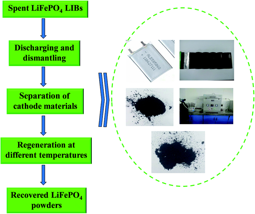
Spent LiFePO4 LIBs and new LiFePO4 powders were both provided by Shandong Weidong novel energy automobile co., Ltd of China. N-Methyl pyrrolidone (NMP), dimethyl formamide (DMF), dimethyl acetamide (DMAC), dimethyl sulfoxide (DMSO) and other chemicals in the experiments were all purchased from Tianjin Kaitong Chemical Company of China with analytical-grade.Fig. 1 shows a flowchart of the whole regeneration process for spent LiFePO4 LIBs in this work. Firstly a discharging pretreatment step was used for the given process before the dismantling of the battery steel shell. Secondly the spent LIBs were manually dismantled by steel saw and knife to get cell core, and then the cell core got dismantled to separate the cathode and anode plate. Thirdly the cathode plate was soaked in the organic solvent to separate the cathode materials and Al for the following regeneration. Finally the spent materials were directly regenerated by solid phase sintering method in the optimal conditions.
 | ||
| Fig. 1 The flowchart of regeneration process for spent LiFePO4 LIBs in this work. | ||
Battery dismantling, separation and regeneration
In this experiment the spent battery was used from electric vehicles. Firstly the discharged battery was dismantled by steel saw, taking out the battery core. Secondly the soft packing of battery core was cut with scissors, getting the winding cathode and anode plates together. Finally the cathode and anode plates were separated using the small knife, wherein the separator and anode plates were reserved for other use, the cathode plates were used for separating experiment. All steps in this dismantling procedure were carried out using safety glasses, gloves and gas masks for safe operation.The positive plates were firstly cut into small plates of 1 cm × 1 cm, and soaked in a beaker containing different environmental-friendly organic solvents, which were placed in thermostatic water bath with different temperature conditions (30, 40, 50, 60, 70 °C). After a period of time, the cathode materials could automatically fall off, and part of the residues could be wiped out manually. The black powder was collected after filtration and dried at 60 °C for 24 h. In this work, the proper organic solvent could be selected as follows: N-methyl pyrrolidone (NMP), dimethyl formamide (DMF), dimethyl acetamide (DMAC) and acetone.22,23 The separating agents, separation temperature, separation time and solid-to-liquid ratio were attached great significance to be investigated. After the solution was maintained still for a while, the supernatant was collected for later re-use.
A certain amount of spent LiFePO4 powder was placed in porcelain boat, and quickly put into a tube heating furnace. Then the furnace was sealed and bubbled into N2 for 15 min, subsequently adjusting the volume of N2 until maintaining constant. Afterwards the spent materials were regenerated at different temperatures for 8 h by solid phase sintering with the heating rate of 5° min−1. Finally the samples were taken out with natural cooling after completion of sintering. In this experiment high temperature regenerations (600 °C, 700 °C, 800 °C) with doping of new LiFePO4 powder at the ratio of 1:9, 2:8, 3:7 were investigated.
Material characterization and battery testing
XRD characterization of spent LiFePO4 was performed on D/MAX 2550 X-ray diffraction analyzer (from Japan) using Cu K_ radiation (λ = 1.54 Å) at 300 mA and 40 kV. The morphology of spent LiFePO4 was examined by ESEM Quanta-200FEG FEI scanning electron microscopy (SEM) technique.The working electrodes were prepared by mixing 80 wt% regenerated materials, 10 wt% conductive agent (carbon black, Super-P), and 10 wt% binder (polyvinylidene difluoride, PVDF). Swagelok-type cells were used with lithium foil as both the counter and reference electrodes, and with 1.0 M lithium hexafluorophosphate (LiPF6) in EC + DEC + DMC (vol. 1:1:1) as the electrolyte. The galvanostatic charging/discharging measurements were conducted in a voltage window of 2.5–4.1 V using a LAND battery tester. The specific capacity was calculated based on the mass of cathode materials.
Results and discussion
Separation of Al and cathode materials
Al and cathode materials were quite difficult to completely separate due to the strong binding force supplied by the polyvinylidene fluoride (PVDF) although some particles may be partially separated after long charge and discharge cycles (shown in Fig. 6). When adhesive on the surface of current collector was fully dissolved by organic solvent, the cathode material would fall off naturally. Therefore the key point for separation of Al and cathode materials lies in the effective dissolution of adhesive in the electrode of LIBs (PVDF). In theory, the full process for separating cathode materials from Al foil can be divided into three phases: liquid infiltrating to the surface of PVDF adhesive, dissolving the adhesive, and detaching the cathode materials. Fig. 2 simulates the dynamic graphs on the surface of current collector during the separation process.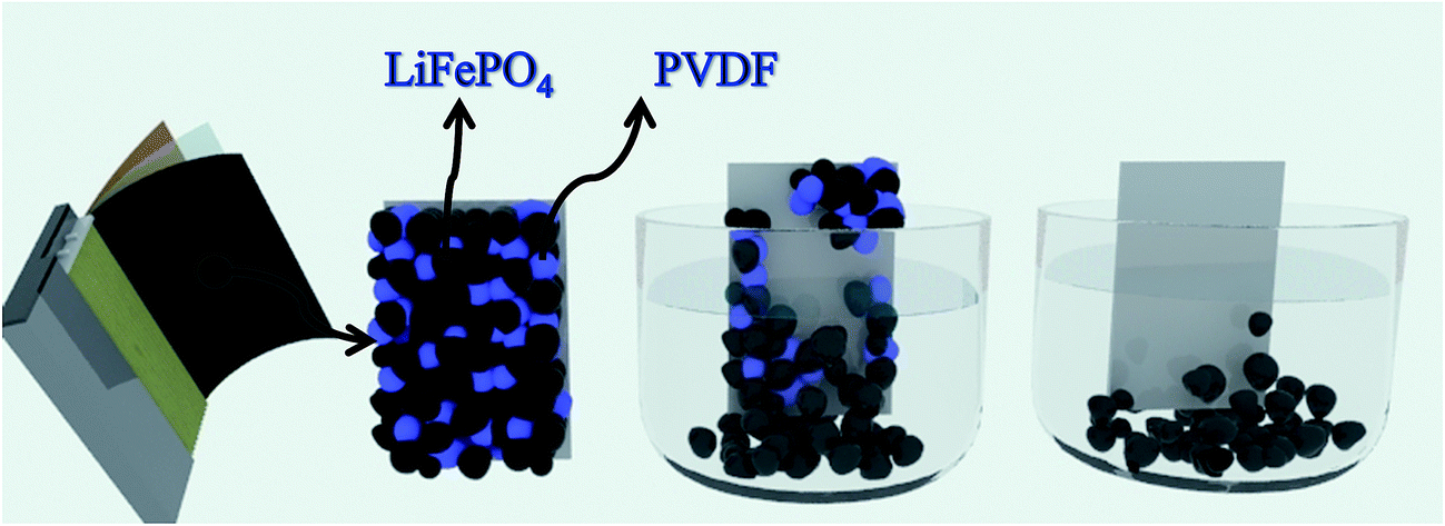 | ||
| Fig. 2 Schematic diagram of process for separating cathode materials from Al foil: liquid infiltrating to the surface of PVDF adhesive, dissolving the adhesive, and detaching the cathode materials. | ||
Organic solvents that can dissolve PVDF include NMP, DMF, DMAC, DMSO and acetone according the literatures. The dissolution phenomena of cathode plates in different solvents are shown in Fig. 3. It must be pointed out that the dissolution results are drawn from at least 20 batteries of parallel tests, and each group contains organic solvent immersion and manual wiping. It indicates that NMP, DMAC and DMF are better for dissolving PVDF. Considering the higher price of NMP, DMAC and DMF are more desirable. Meanwhile as to DMAC and DMF, when used as primary solvent, their separation efficiencies are proximate. Both of them can react with PVDF quickly and thus make LiFePO4 coat fall off quickly. When they are used as secondary solvent, DMAC's separation efficiency is remarkably higher than that of DMF, as shown in Fig. 4d. Taking all above into considerations, DMAC is chosen to be the best solvent of PVDF.
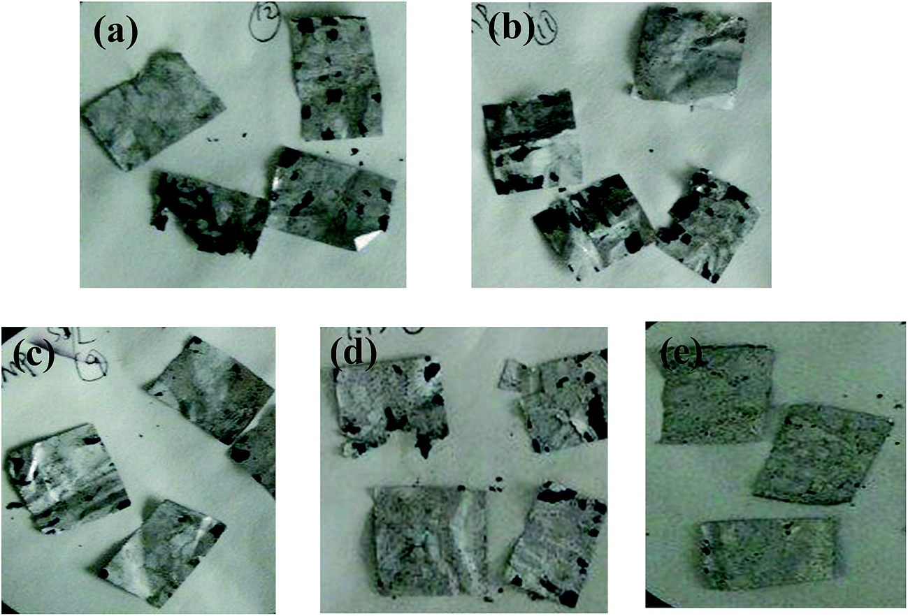 | ||
| Fig. 3 The dissolution phenomena of cathode plates in different solvents: (a) DMSO; (b) acetone; (c) DMF; (d) NMP; (e) DMAC. | ||
 | ||
| Fig. 4 Effects of several factors on separation efficiency: (a) temperatures; (b) duration; (c) solid-to-liquid ratio; (d) separation efficiency of DMAC and DMF used as secondary solvent. | ||
The effects of temperatures on separation efficiency at separation duration of 30 min and solid–liquid ratio of 1:20 g ml−1 are shown in Fig. 4a. The tendency of separation efficiency with temperature increasing is not obvious. When the separation temperature reaches 30 °C, the separation efficiency maintains stability. Therefore temperature does not significantly affect separation process, thus the optimal separation temperature is selected at 30 °C in this experiment. Effects of separation duration were studied at temperature of 30 °C and solid–liquid ratio of 1:20 g ml−1, changing from 2 min to 20 min. The accordingly separation efficiencies are observed in Fig. 4b. In this experiment, the aluminum foil is almost fallen off at 1 min. Similarly, changes of separation efficiency are not obvious with the time extension, which illustrates that the reaction of the adhesives and organic solvent is very quickly. The effect of solid-to-liquid ratio on the separation efficiency was studied at 30 °C and 5 min. The solid-to-liquid ratios are changed from 1:5 g ml−1 to 1:20 g ml−1 to conduct the experiment. The results between solid-to-liquid ratio and separation efficiency are displayed in Fig. 4c. When solid-to-liquid ratio was set at 1:5 or 1:8, spent LiFePO4 could hardly fall off from aluminum foil, thus making later manual scraping much more difficult. When solid-to-liquid ratio was set at 1:10 or higher than 1:10, spent LiFePO4 began to fall off quickly and completely.
Fig. 2 simulates the liquid infiltration and diffusion on the surface of current collector during the separation process. It demonstrates that in the separation process, the increasing amount of liquid can significantly increase the osmotic quantity to internal materials, thus promoting the dissolution reaction of adhesives and organic solvent. Meanwhile the increasing amount of liquid can simultaneously increase the diffusion of the liquid to the outside, consequently improving the speed of reaction. In conclusion, the effect of solid-to-liquid ratio is the largest to the separation efficiency.
XRD and SEM results of spent LiFePO4 after separation
The XRD and SEM results of spent LiFePO4 can be observed in Fig. 5. From the X-ray diffraction, the phase components are observed to be LiFePO4, FePO4, FeO and Fe3O4, etc. The FePO4 contained in the cathode materials may come from transformation of LiFePO4 during the process of charge and discharge, while appearance of FeO and Fe3O4 may result from the decomposition of LiFePO4 after several cycles. Meanwhile the intensities and 2-theta positions of some diffraction peaks of LiFePO4 have much difference with the raw LiFePO4, which means the structure of spent LiFePO4 has been much changed. Moreover the obvious amorphous transformation on XRD patterns indicates that olivine structure of LiFePO4 appears structural deformation after several inserting and removing of lithium ions in the cathode materials.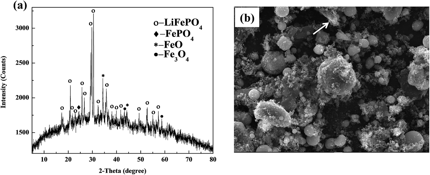 | ||
| Fig. 5 XRD patterns and SEM image of spent LiFePO4 after separation: (a) many impurity phases including FePO4, FeO and Fe3O4; (b) irregular particle with many agglomerations. | ||
From the SEM image, the morphology and particle size of spent LiFePO4 appear much irregular with many agglomerations, which are much different than the raw LiFePO4. Some particles in spent LiFePO4 mainly comprise lithium and other particles mainly carbon. This means that after several charge and discharge cycles, the adhesives (mainly PVDF, shown as arrows) in spent batteries begin to form a lump. The lumps of adhesives prevent the electronic transmission and electrochemical reactions because they are themselves insulators. Therefore the spent LiFePO4 from spent LIBs cannot be directly used as the active material of new battery, and need to be recovered.
Failure mechanism of LiFePO4 for Li-ion batteries
Based on the above results, the failure mechanism of LiFePO4 battery is analyzed in this paper shown in Fig. 6. Firstly cathode solid electrolyte interface film is a relatively stable and protective film formed on the surface of the electrode to prevent the electrolyte solvent from being further reduced. However during the process of intercalation and deintercalation of Li+, produced stress can lead to the breakdown of interface film and decomposition of LiFePO4, and thus resulting to exposed new electrode surface with electrolyte solvent. Therefore Li+ and solvent would be consumed to repair the SEI film. After repeated cycles, the capacity of battery will gradually decline due to consumption of Li+ and electrolyte. Secondly the properties of binder will decline gradually as the proceeding of charge and discharge cycles. The decreased bonding strength can lead to active material loosen and even partially falling off from the electrodes, which result in increased battery internal resistance, battery capacity decline, and poor cycle performance. Thirdly electrolyte is generally made up of solute, solvent and special additives, and plays an important role on ion transportation and current conduction. After a long cycle electrolyte degradation happens accompanied by gas generation (mainly HF). Therefore the electrodes cannot all immerse into the electrolyte because of gradually lack of electrolyte, which will lead to incompletely electrochemical reaction and unsatisfactory battery capacity.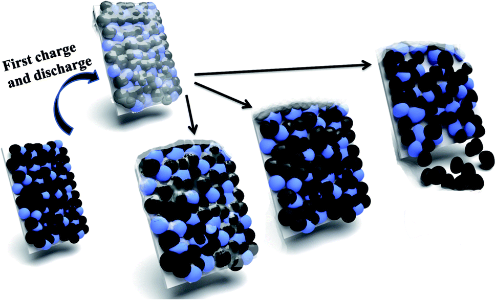 | ||
| Fig. 6 Illustration of failure mechanism of LiFePO4 for Li-ion batteries: breakdown of SEI film; decomposition of LiFePO4; falling of cathode materials. | ||
XRD and SEM results of regenerated LiFePO4
XRD patterns of regenerated materials with new LiFePO4 doping at high temperature (600 °C, 700 °C, 800 °C) are shown in Fig. 7. It can be seen from the figures that the main peaks are all derived from characteristic peaks of LiFePO4, moreover with no significant differences at any temperatures (600 °C, 700 °C, 800 °C). Meanwhile the peaks of LiFePO4 has become flat, illustrating that the amorphous phenomenon begins reduced or disappeared. The shape of peaks has become sharp, demonstrating that crystallization of LiFePO4 has been regained from the regeneration.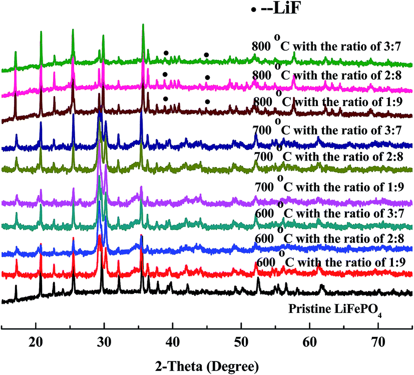 | ||
| Fig. 7 XRD patterns of regenerated materials with doping new LiFePO4 at different temperature and ratio. | ||
Under the condition of high temperature at 600 °C with new LiFePO4 doping XRD patterns have become sharper, which is a good demonstration of high crystallinity from regenerated LiFePO4. Phase compositions of crystals are similar to standard LiFePO4 with almost no impurity peaks. Results of 700 °C are mainly the same as 600 °C with more and more flat and sharp peaks from LiFePO4 with no impurity peaks. However when the temperature is further increased to 800 °C, peaks of LiF begin to appear in addition to the main peaks of LiFePO4. It is mainly because at this point HF is nearly generated from the decomposition of incompletely-disposed PVDF during the process of separation. PVDF, as the adhesives of LiFePO4 battery, has the decomposition temperature of above 400 °C, and could be inevitably decomposed under the condition of high temperature regeneration. It must be pointed out that new LiFePO4 doping can firstly promote the crystallization of reaction between iron phosphate and ferric oxide, and thus making some impurity phase disappear. Secondly it can inhibit the decomposition of PVDF to some extent and indirectly prevent the reaction of LiFePO4 and HF, which gives sufficient evidence for no or less existence of LiF at the temperature of 600 °C and 700 °C.
SEM images of regenerated materials with new LiFePO4 doping at high temperature (600 °C, 700 °C, 800 °C) are shown in Fig. 8. We can see from the figures PVDF residuals (shown as arrows in the Fig. 8) are all widespread on regenerated LiFePO4 material regardless of the temperature and ratio. And in a certain temperature range PVDF residues will decrease with the rising of temperature. According to the literatures the effects of PVDF residues on the electrochemical performances of batteries are not so much significant, which is mainly because the regenerative cell itself needs to be added with PVDF in the process of re-assembly and the residual PVDF after fully dispersed can also play a role in bonding.17 Actually the impedance result can be observed from Fig. 9. It shows no much difference among the regenerated samples and commercial LiFePO4. Therefore, the existence of PVDF is acceptable here.
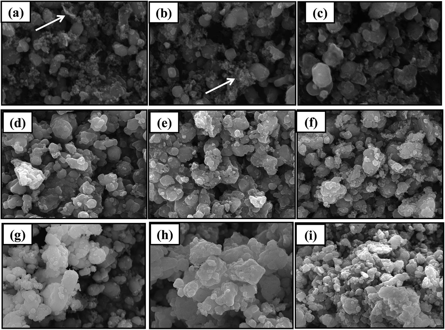 | ||
| Fig. 8 SEM images of regenerated materials with doping new LiFePO4 at different temperature and ratio: (a–c) 600 °C with doping at 1:9 to 3:7; (d–f) 700 °C with doping at 1:9 to 3:7; (g–i) 800 °C with doping at 1:9 to 3:7. | ||
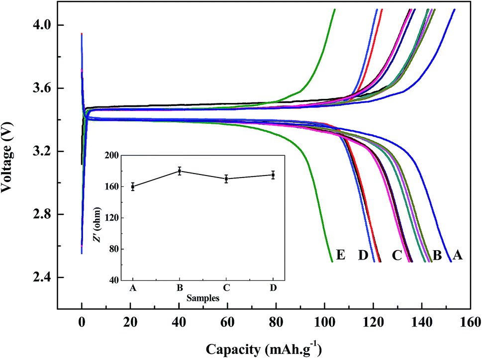 | ||
| Fig. 9 Discharge/charge voltage and impedance profiles of regenerated LiFePO4 at a current density of 0.1C: (A) commercial LiFePO4; (B) 700 °C with the ratio of 1:9, 2:8, 3:7; (C) 600 °C with the ratio of 1:9, 2:8, 3:7; (D) 800 °C with the ratio of 1:9, 2:8, 3:7; (E) regenerated without doping new LiFePO4. | ||
Under the regeneration of new LiFePO4 doping, the particle distribution uniformity begins to appear high at 600 °C. Although a small amount of PVDF can be observed, but the agglomeration phenomenon does not exist overall. Results of 700 °C are mainly the same as 600 °C with more and more uniform particle distribution and less agglomeration. Under the condition of 800 °C, the size of the particle has become larger companying with phenomenon of agglomeration, which is detrimental to the performance of the battery.
Battery performance based on regenerated LiFePO4
The charge/discharge profiles within a cut-off voltage window of 2.5–4.1 V are shown in Fig. 9. It can be seen from the figures that battery capacities from regenerated LiFePO4 can both reach over 120 mA h g−1 at 0.1C discharge conditions with the same discharging platform, and moreover with no significant differences at any doping ratio (1:9, 2:8, 3:7). While battery capacities with doping of new LiFePO4 at 800 °C are much worse than those with doping of new LiFePO4 at 600 °C and 700 °C. This is mainly due to impurity phase (mainly LiF) and inhomogeneous morphology distribution existing in the regenerated materials when doping of new LiFePO4 at much high temperature, which does great harm to the battery capacity. When doping with new LiFePO4 at 600 °C and 700 °C, batteries made from regenerated materials with pure phase and uniform morphology can meet the basic requirements for reuse. Especially when doping ratio with 3:7 at the temperature of 700 °C, battery capacity is the highest of 144 mA h g−1. For comparison, the battery performance of regenerated sample without doping new LiFePO4 and commercial LiFePO4 can also shown in Fig. 9. Battery capacity of commercial LiFePO4 is a little higher than that of regenerated material. However the sample regenerated without doping new LiFePO4 cannot meet reuse requirements due to low initial capacity of 102 mA h g−1.
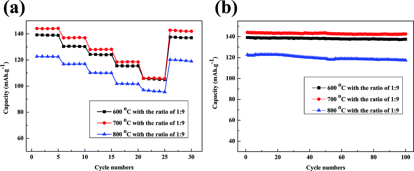
The rate capabilities of batteries made from regenerated LiFePO4 with the doping ratio of 1:9 are shown in Fig. 10a. The discharge capacities gradually decrease as the current rate increases from 0.1C to 5C. Firstly rate capabilities of batteries have been retained over than 110 mA h g−1 at low current rate of 0.1C, 0.5C and 1C. Meanwhile a satisfactory capacity of more than 105 mA h g−1 is obtained at high current rate of 2C and 5C when regeneration temperature at 600 °C and 700 °C. Only the 5C discharge capacity at 800 °C is lower than 100 mA h g−1. Moreover the regenerated materials recover most of the capacity when the current rate is reduced back to 0.1C. Fig. 10b gives the cycling performance of batteries made from regenerated LiFePO4 at a constant current density of 0.2C. The batteries with doping of new LiFePO4 show much better cycling stability with a reversible capacity of over 135 mA h g−1 after 100 cycles when regeneration temperature at 600 °C and 700 °C. The better capacity retention can probably be attributed to the pure phase and uniform morphology with doping of new LiFePO4 after regeneration.
 | ||
| Fig. 10 (a) Rate capabilities of regenerated LiFePO4 at a current rate of 0.1C, 0.5C, 1C, 2C, 5C; (b) cycling performances of regenerated LiFePO4 at a current density of 0.1C with 100 cycles. | ||
Conclusions
In summary, we have successfully regenerated cathode materials of spent LiFePO4 battery by direct solid phase sintering method in this article. The spent battery is firstly dismantled to separate the cathode and anode plate, and then the cathode plate is soaked in the environmental-friendly organic solvent (can be cycle used) to separate the cathode materials and Al foils. The optimal separation is proposed to be 30 min at 30 °C and solid–liquid ratio of 1:20 g ml−1 in the solvent of DMAC. Finally the spent LiFePO4 was directly regenerated with doping of new LiFePO4 by solid phase sintering method. Battery capacities from regenerated LiFePO4 can both reach over 120 mA h g−1 at 0.1C discharge conditions, and meanwhile with the highest of 144 mA h g−1 when doping ratio of 3:7 at the temperature of 700 °C. The rate capabilities and cycling performance of batteries made from regenerated LiFePO4 with doping when regeneration temperature at 600 °C and 700 °C are generally better than those at 800 °C. All the performances of batteries made from regenerated LiFePO4 with pure phase and uniform morphology can meet the basic requirements for reuse.
Acknowledgements
The authors gratefully acknowledge the financial support from natural science foundation of Hubei Province (No. 2014CFB559 and 2014CFB556), the Foundation of Wuhan Chenguang Planning Project of Science and Technology (No. 2014070404010213) and the Projects of Hubei provincial Education Department Scientific research (No. B2014255).The authors would like to thank the Analytical and Testing Center of Hubei University for providing the facilities to fulfill the experimental measurements.References
- J. Owen and A. Hector, Science, 2014, 344, 1451–1453 CrossRef CAS PubMed.
- B. Dunn, H. Kamath and J. M. Tarascon, Science, 2011, 334, 928–935 CrossRef CAS PubMed.
- L. H. Hu, F. Y. Wu, C. T. Lin, A. N. Khlobystov and L. J. Li, Nat. Commun., 2013, 4, 1687–1694 CrossRef PubMed.
- S. M. Oh, S. T. Myung, J. B. Park, B. Scrosati, K. Amine and Y. K. Sun, Angew. Chem., 2012, 51, 1853–1856 CrossRef CAS PubMed.
- R. Amisse, M. T. Sougrati, L. Stievano, C. Davoisne, G. Drazic, B. Budic, R. Dominko and C. Masquelier, Chem. Mater., 2015, 27, 4261–4273 CrossRef CAS.
- D. P. Singh, F. M. Mulder, A. M. Abdelkader and M. Wagemaker, Adv. Energy Mater., 2013, 3, 572–578 CrossRef CAS.
- Z. J. Li, Z. Z. Peng, H. Zhang, T. Hu, M. M. Hu, K. J. Zhu and X. H. Wang, Nano Lett., 2016, 16, 795–799 CrossRef CAS PubMed.
- Y. Zhao, L. L. Peng, B. R. Liu and G. H. Yu, Nano Lett., 2014, 14, 2849–2853 CrossRef CAS PubMed.
- L. Wang, X. M. He, W. T. Sun, J. L. Wang, Y. D. Li and S. S. Fan, Nano Lett., 2012, 12(11), 5632–5636 CrossRef CAS PubMed.
- C. Y. Nan, J. Lu, L. H. Li, L. L. Li, Q. Peng and Y. D. Li, Nano Res., 2013, 6(7), 469–477 CrossRef CAS.
- S. L. Yang, X. F. Zhou and J. G. Zhang, J. Mater. Chem. A, 2010, 20(37), 8086–8091 RSC.
- H. Liu, F. C. Strobridge, O. J. Borkiewicz, K. M. Wiaderek, K. W. Chapman, P. J. Chupas and C. P. Grey, Science, 2014, 344(6191), 1480–1488 CrossRef CAS PubMed.
- M. Gu, W. Shi, J. M. Zheng, P. F. Yan, J. G. hang and C. M. Wang, Appl. Phys. Lett., 2015, 106, 203902 CrossRef.
- T. Zhang, Y. Q. He, F. F. Wang, H. Li, C. L. Duan and C. B. Wu, Sep. Purif. Technol., 2014, 138, 21–27 CrossRef CAS.
- T. Zhang, Y. Q. He, L. H. Ge, R. Fu, X. Zhang and Y. J. Huang, J. Power Sources, 2013, 240, 766–771 CrossRef CAS.
- X. L. Zeng and J. H. Li, J. Hazard. Mater., 2014, 271, 50–56 CrossRef CAS PubMed.
- S. Natarajan, D. S. Lakshmi, H. C. Bajaj and D. N. Srivastava, J. Environ. Chem. Eng., 2015, 3, 2538–2545 CrossRef CAS.
- X. L. Zeng, J. H. Li and L. L. Liu, Renewable Sustainable Energy Rev., 2015, 52, 1759–1767 CrossRef CAS.
- X. P. Chen, B. L. Fan, L. P. Xu, T. Zhou and J. R. Kong, J. Cleaner Prod., 2016, 112, 3562–3570 CrossRef CAS.
- M. T. Georgi, B. Friedrich, R. Weyhe, H. Heegn and M. Rutz, J. Power Sources, 2012, 207, 173–182 CrossRef.
- M. J. Ganter, B. J. Landi, C. W. Babbitt, A. Anctil and G. Gaustad, J. Power Sources, 2014, 256, 274–280 CrossRef CAS.
- X. H. Zhang, Y. B. Xie, X. Lin, H. T. Li and H. B. Cao, J. Mater. Cycles Waste Manage., 2013, 15(4), 420–430 CrossRef CAS.
- M. Contestabile, S. Panero and B. Scrosati, J. Power Sources, 2001, 92, 65–69 CrossRef CAS.
Footnote |
| † These two authors contribute equally to this work. |
| This journal is © The Royal Society of Chemistry 2017 |