
 Open Access Article
 This Open Access Article is licensed under a
 Creative Commons Attribution 3.0 Unported Licence
Combined thermal and FTIR analysis of porous silicon based nano-energetic films†
A. Plummer a,
V. A. Kuznetsovab,
J. R. Gascookea,
J. Shapterac and
N. H. Voelcker*d
a,
V. A. Kuznetsovab,
J. R. Gascookea,
J. Shapterac and
N. H. Voelcker*d
aCentre of Expertise in Energetic Materials, School of Chemical and Physical Sciences, Flinders University, 5042, Bedford Park, Australia
bWeapons and Combat Systems Division, Defence Science and Technology Group, Edinburgh, SA 5111, Australia
cCentre for Nanoscale Science and Technology, School of Chemical and Physical Sciences, Flinders University, 5042, Bedford Park, Australia
dFuture Industries Institute, University of South Australia, 5095, Mawson Lakes, Australia. E-mail: nico.voelcker@unisa.edu.au; Tel: +61 8 8302 5508
First published on 23rd January 2017
Abstract
Nanoporous silicon (pSi) films on a silicon wafer were loaded with sodium perchlorate (SP) and perfluoropolyether (PFPE) oxidising agents to generate a pyrotechnic energetic material. The potentially violent reaction between the silicon and the loaded oxidising agent was studied using correlated differential scanning calorimetry (DSC) and FTIR spectroscopy for samples heated continuously between ambient and 500 °C. We observed that the energetic reaction between pSi and SP depended on the presence of various hydride species on the surface of freshly etched pSi, and on formation of volatile free radical species released during either oxidation of the surface in the presence of air at about 200 °C or during desorption of the hydride above 270 °C in the absence of oxygen. However, energetic reactions between pSi and PFPE were delayed until pyrolysis of the PFPE above 390 °C in the absence of oxygen, suggesting PFPE's suitability for pyrotechnics applications. Correlated thermal and spectroscopic methods of analysis gave new insights into the earliest stages of the reaction of these energetic materials.
Introduction
Porous silicon (pSi) is a nanostructured material prepared by the electrochemical etching of silicon wafers using various hydrofluoric acid (HF) based etching solutions resulting in nano- to micro-metre sized cavities in the surface whilst leaving the bulk dimensions of the wafer unchanged.1 Manipulation of the etching conditions permits precise control over the resulting porous layer, including the size of the pores, the shape (from highly ordered channels to highly disordered sponge-like structures), depth and overall porosity.1 The explosive behaviour of pSi films impregnated by an oxidising agent has been recognised and steadily investigated since 1992.2 The behaviour originates from the very high internal surface area of pSi (up to 800 m2 g−1) permitting a very intimate mixture between the oxidising agent and the fuel (silicon), leading to materials that are relatively stable at room temperature and are able to react explosively upon application of an energy stimulus. Indeed, pSi energetic materials (pSi EM's) prepared in this way are sensitive to a wide variety of stimuli. Methods of initiation that have been reported include heating using, for example, a hot-plate3 or a hot bridge-wire,4,5 mechanical stimulus (such as scratching the surface or friction),6 or an electrical spark.6,7 Additionally, laser ignition of pSi energetic materials has been reported using a variety of wavelengths and laser fluences.6,8–10A variety of oxidising agents (typically nitrate or perchlorate salts) have been shown to react energetically with pSi. Sodium perchlorate (SP) has emerged as the oxidiser of choice since it delivers the most powerful and consistent energetic reaction.2 Conveniently, controlling the material properties of the pSi substrate (by tuning the etching conditions) permits control over the stoichiometry of the system by limiting the volume of the pores available to be filled. The burning rate of pSi energetic films has been reported from as high as 3600 m s−1 (ref. 11) to less than 1 m s−1.12 The choice of oxidising agent, porosity, pore depth and pore diameter are all interdependent factors which govern the burning rate of the system. Fluorinated polymers (such as perfluoropolyether (PFPE)) have recently been investigated as an alternative to ionic oxidising agents, with reported burning rates typically less than 1 m s−1.12
It is recognised that pSi EM's can be excessively sensitive, rendering those materials ill-suited for real world applications such as MEMS actuators or air-bag initiators envisaged in earlier works.2,10,13 Knowledge of the reaction mechanism between pSi and an oxidising agent is an important factor to help understand the excessive sensitivity, and may assist in the selection of oxidising agent or material treatment regimes in order for these materials to be translated into real-world applications.
Simple bomb calorimetry can determine the total energy released during reaction of a material.14 However, the reaction of an energetic material involves sometimes complex decomposition stages and formation of intermediate species. Investigation of these processes by controlled thermal analysis methods can yield important information, including reaction endo- and exotherms, or intermediate transition or decomposition temperatures all of which gives an insight to the mechanism of the reaction.15
Investigating the reaction between the pSi surface with liquid oxygen, Kovalev et al.16 first proposed that hydride termination of the freshly etched pSi surface was an essential passivating barrier to prevent spontaneous oxidation. Rupturing the Si–H surface bonds or sub-surface Si–Si bonds by various means created free radicals susceptible to reaction with oxygen. The exothermic reaction between a single Si atom and oxygen molecule releases sufficient energy to disrupt neighbouring bonds. A single point of initiation can then rapidly cascade up to an explosive reaction.
Churaman et al.17 investigated the mechanism of the reaction between a pSi film (approx. 4 nm pore diameter, 40 μm layer thickness) and SP. Using differential scanning calorimetry (DSC) dehydration endotherms of the monohydrated SP within the pSi pores were observed at approximately 51 °C and 149 °C, a phase transition of the SP at 307 °C, and finally an explosive reaction at 320 °C. No significant exotherms were observed below the temperature of explosion. They concluded that the mixture commenced reaction initially by formation of reactive ions through dissociation of the SP or H2O during these dehydration steps, which are then free to react with the pSi surface. Again it was observed that the presence of the hydride termination on the pSi surface was essential to promote a strong explosive reaction.
Becker et al.18 investigated the influence of atmospheric conditions on the reactivity of pSi films impregnated with SP. Using bomb calorimetry, freshly etched pSi prepared by galvanic corrosion (up to 150 μm thick layers, 62 to 69% porosity, pore sizes 2.7 to 3.1 nm) loaded with SP yielded gross reaction enthalpies of 9.9 kJ g−1 of pSi in a N2 atmosphere and 27.3 kJ g−1 in O2. They further observed that oxygen back bonding beneath the hydride-terminated pSi surface resulted in a weak exotherm at about 250 °C. This was confirmed by FTIR spectroscopy. In the absence of the hydride termination, no energetic reaction was observed. Hence, the presence of the hydride termination on the pSi surface was essential to enabling the material to react explosively according to the authors. They further concluded that the substantial difference in the total energy of the reaction recorded between N2 and O2 atmospheres was due to the mixture being substantially fuel rich (a limitation imposed by the available pore volume within the pSi layer), thereby allowing remaining Si to react with the oxygen after the main reaction with the SP.
Parimi et al.19 studied the reactivity of various pSi EM's using DSC and TGA, investigating the influence of doping type and doping concentration of the original Si wafer. Wafer dopant concentration and type influenced the reactivity of the material, not directly by contributing to the reaction between the pSi and the oxidising agent, but indirectly by impacting on the morphology and specific surface area of the pSi generated by means of anodisation. Studying the propagation of the flame through pSi EMs of different morphology,20 the authors observed that the peak temperature of the first and strongest exotherm (which was attributed to the solid phase reaction between pSi and SP) shifted to lower temperatures as the specific surface area of the pSi increased, from approximately 400 °C at a surface area of 284 m2 g−1 to approx. 280 °C at a surface area of 730 m2 g−1. A calculation of the activation energies for these two materials gave values of 124.5 kJ mol−1 for the low surface area pSi and 72.1 kJ mol−1 for the high surface area pSi. From those calculations and others, it was determined that the propagation of the flame through pSi was due to a combination of both conductive and convective burning, not simply a conductive mechanism as observed in other solid-phase energetic materials.
Infrared spectroscopy is a versatile technique often applied to pSi research due to the wealth of information available about the chemical structure of this high surface area material. Oxidation of a pSi surface heated continuously in an O2 atmosphere was observed by Mawhinney et al.21 with the results showing that the reaction proceeded initially by insertion of oxygen into the Si–Si bonds behind the Si–H surface species when the temperature exceeded 300 °C. As the oxidation proceeded, the hydride species were gradually replaced by hydroxyl groups and eventually, the surface was completely oxidised. Likewise, Salonen et al.22 used FTIR in combination with DSC, showing a strong exothermic reaction of pSi heated in air commencing at about 200 °C, peaking at approximately 300 °C and attributed this to back bond oxidation of the pSi surface. Furthermore, a broad exothermic tail observed in the DSC rising from about 400 °C and terminating at approx. 650 °C was attributed to the formation of surface hydroxyl groups. However, in their study Salonen et al.22 cooled the samples after heating, prior to FTIR analysis.
Both DSC and FTIR studies independently yield valuable information about the structure of pSi and the possible reaction pathways. Significantly, Mawhinney et al.21 recognised the need to continuously record spectra during the heating process to minimise kinetic effects caused by cooling of a heated sample prior to measurement. Such problems would be exacerbated for the fast reacting pSi EM's studied here. It is therefore the aim of this work to combine these two techniques to obtain valuable real-time spectroscopic information regarding the reaction of pSi, and to correlate that to observed reactions in the thermal analysis.
Materials and methods
Porous silicon preparation
Porous silicon was prepared from p-type boron doped wafers, 3–6 Ω cm resistivity, 〈100〉 orientation, supplied by Virginia Semiconductors. Hydrofluoric acid (48% aqueous solution, Merck Chemicals) was diluted with acetonitrile to a final volumetric concentration of 20%. Electrochemical etching was conducted using standard techniques1,3 in a Teflon etching cell incorporating a platinum cathode and stainless steel anode.23 The etching cell used in these experiments produced an etched area 45 mm long by 8 mm wide (etch area of 3.79 cm2). Electrochemical etching was performed by a TTi PLH-250 power supply, operated under conditions of constant current controlled by a purpose-built LabVIEW interface on a Windows PC. The applied current was pulsed with a 66% duty cycle (10 s on, 5 s off), for a desired number of cycles, at a current density of 45 mA cm−2 for an applied current time of 30 minutes (45 min's total etch time). Previous work has determined that these etching conditions produce pSi surfaces with pore sizes of 3.6 ± 1.4 nm, a porosity of 64.7 ± 0.5% and a depth of 42.9 ± 0.4 μm.23 Wafers were washed with ethanol and acetone prior to and after etching, and dried in a stream of N2 gas. All samples were stored in a desiccator when not being handled. For all investigations reported here, the pSi layer remained attached to the supporting Si wafer. In this configuration, only the pSi forms the reactive material and the supporting wafer takes no part in the reaction.24 These wafers were cut into suitably sized smaller samples (approximately 4 × 4 mm2 for DSC experiments and approximately 4 × 8 mm2 for FTIR experiments) prior to loading with the oxidising agent.Loading of oxidant into pSi
A stock solution of SP monohydrate (Ajax Chemicals) was prepared at a concentration of 400 g L−1 in methanol. The solution of the selected oxidising agent was micropipetted onto the wafer and impregnated into the pores as the solvent evaporated in a stream of N2 gas, leaving the oxidising agent deposited into the pores, an effect substantially exacerbated for wafers that were sectioned for DSC/FTIR analysis. As had been noted elsewhere,13,18 crystals of SP would tend to nucleate on the surface instead of within the pores as the solvent evaporated. This effect could be reduced by careful evaporation using a gentle stream of N2, and small residual surface crystals not contributing to the energetic reaction were gently removed prior to analysis.Secondly, a stock solution of the PFPE (Fomblin Y HVAC 25/9) was prepared at a concentration of 200 g L−1 in the fluorinated solvent perfluoro(butyltetrahydrofuran) (Fluorinert FC-75). Fomblin Y is a high viscosity liquid at room temperature. Impregnation of this material into the pores required the stock solution to be pipetted onto the surface, followed by evaporation under vacuum in a desiccator with subsequent back-filling of the vessel using N2 – three successive steps were required in order to load the wafer.
The mass of the EM (i.e. the net explosive quantity) was determined gravimetrically. Samples were weighed prior and subsequent to loading with the oxidising agent, and the unreactive supporting wafer was weighed subsequent to analysis once the pSi layer had been stripped away using dilute aqueous potassium hydroxide.
Thermal analysis
DSC experiments were conducted on a TA Instruments 8020 DSC at a heating rate of 20 °C min−1, in open aluminium pans with a chamber purge gas of either dry air (BOC Instrument grade compressed air, <25 ppm H2O25) or N2 at a rate of 50 mL min−1, between ambient and 600 °C.Spectroscopic analysis
FTIR experiments were conducted separately to the DSC, conducted on samples prepared and loaded under the same conditions, and under the same heating and atmospheric regime. The instrument used was a Nicolet Nexus 870 FTIR using a liquid N2 cooled MCT detector and 16 scans per measurement point. Samples were heated by conduction on a Linkam FTIR600 hot stage accessory, heated at rate of 20 °C min−1, with transmission spectra collected between 30 and 510 °C at intervals of approximately 20 °C. This was also run with controlled atmospheres of either N2 or dried air (supplied through a Parker Bailish purge gas generator), and used zinc selenide IR transparent windows. Spectra were all recorded in transmission mode at pre-determined temperatures as the sample was being continuously heated. The temperature of the sample increased by approximately 2 °C during the time taken to actually record the spectra. Whilst it is recognised that this temperature change introduced a small uncertainty, it was felt that this was an acceptably necessary experimental compromise.All spectra collected for an individual sample were background corrected to compensate for the decreasing transparency of Si at the temperatures of these experiments – details of the correction method are provided in the ESI.† Table 1 lists the characteristic spectral peaks for various species involved in this investigation.
| Wavenumber (cm−1) | Transition | Ref. |
|---|---|---|
| 616, 621, 643 | ClO4− vibration | 26 |
| 615, 622, 666 | Si–Hx deformation, overlapped with Si crystal modes | 21 |
| 671, 730, 776 | C–C/C–O/C–F/C–F2/C–F3 stretch | 27 |
| 840 | Si–N asymmetric stretch (>800 °C) | 28 |
| 841, 877 | O–SiHx (unknown mode) | 21 |
| 906 | ClO4− vibration | 26 |
| 915 | Si–H2 scissoring | 21 |
| 940 | Si–F stretch | 29 |
| 950–1250 (broad) | Amorphous Si–O2 absorbance | 21 |
| 980 | Overlapping C–C/C–F2/C–F3 stretch | 27 |
| 1011, 1127, 1192 | ClO4− vibration | 26 |
| 1015, 1121 | Si–O–Si vibration | 21 |
| 1029, 1190, 1826 | Si–F4 (unknown mode) | 30 |
| 1108 | Si–O–Si crystal stretch | 21 |
| 1110 | ClO4− vibration | 26 |
| 1131–1345 | Multiple overlapping C–C/CF2/CF3 stretch | 27 |
| 1157 | C–F3 (unknown mode) | 30 |
| 1200 | C–F stretch | 31 |
| 1283, 1539, 2186, 2561 | C–F4 (unknown mode) | 30 |
| 1300–1150 | C–O–C; C–F stretch | 31 |
| 1372 | Overlapping C–C/CF2/CF3 stretch | 27 |
| 1929 | COF2 (unknown mode) | 30 |
| 2090, 2115, 2141 | Si–Hx stretch | 21 |
| 2214, 2273 | OSi–Hx stretch | 21 |
| 3736 | SiO–H stretch | 21 |
| 3745 | SiO–H stretch | 21 |
| 3750–4250 | H–F stretch | 30 |
Results and discussion
DSC scans obtained for the various samples used in this study are shown in Fig. 1. Each scan has been offset to allow comparison between the different samples. For the same samples, 2D images showing FTIR spectra as a function of temperature are compiled in Fig. 2. Fig. 3 depicts FTIR spectra (extracted from data forming Fig. 2) recorded at 150 °C to allow comparison of each of the material combinations and to highlight the relevant peaks. Each of the eight sample conditions are compared in further detail and presented in the ESI, Fig. S2a to h.†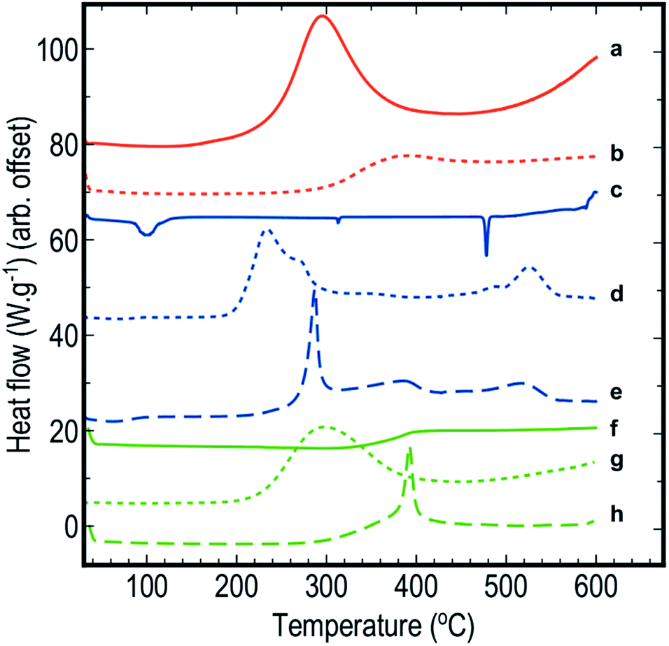 | ||
| Fig. 1 DSC scans of (a) blank pSi in air, (b) blank pSi in N2, (c) blank SP in air, (d) pSi/SP EM in air, (e) pSi/SP EM in N2, (f) blank PFPE in air, (g) pSi/PFPE EM in air, and (h) pSi/PFPE in N2. | ||
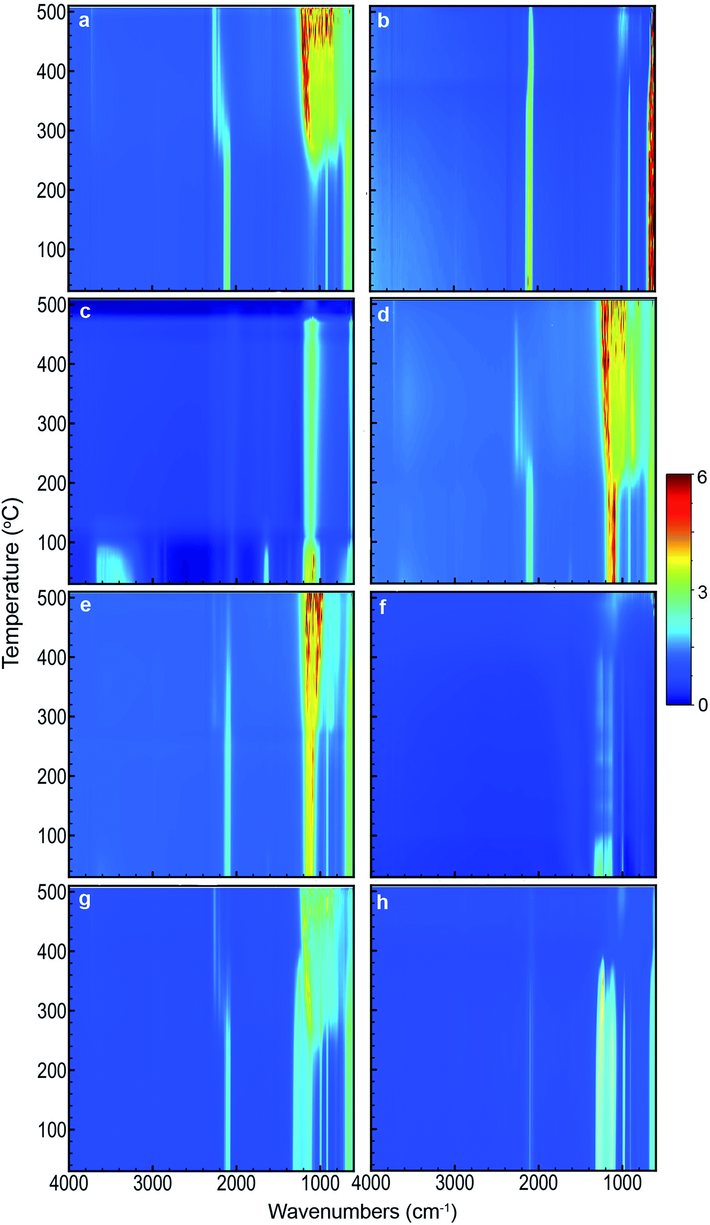 | ||
| Fig. 2 2D FTIR spectra as a function of temperature of (a) blank pSi in air, (b) blank pSi in N2, (c) blank SP in air, (d) pSi/SP EM in air, (e) pSi/SP EM in N2, (f) blank PFPE in air, (g) pSi/PFPE EM in air, and (h) pSi/PFPE in N2. | ||
 | ||
| Fig. 3 FTIR spectra of (a) blank pSi, (b) blank SP, (c) pSi/SP EM, (d) blank PFPE, and (e) pSi/PFPE EM, collected at 150 °C for samples heated in a N2 atmosphere. The triplet of peaks at ≈2109 cm−1 (Si–Hx vibration) and a single peak at ≈910 cm−1 (Si–H2 scissoring) are specific for the pSi surface and clearly distinguished from a strong absorption band between ≈1000 and 1200 cm−1 (associated to multiple perchlorate vibration modes) and a sharp absorption peak at ≈980 cm−1 attributed to overlapping PFPE CF2/CF3 vibrations. | ||
Thermal behaviour of blank pSi
Unloaded pSi displayed significant evidence of oxidation when heated in air (Fig. 1a and 2a). By means of DSC, we observed an onset temperature of the exothermic oxidation reaction at approximately 200 °C peaking at 292 °C. Comparing this to the FTIR spectral data, the main transition between a fresh and oxidised surface was initially visible at between 230 and 250 °C and appeared substantially complete by approximately 350 °C. This is most clearly indicated by the decrease in intensity of the surface hydride triplet peaks (centred at 2109 cm−1) with an associated increase in the back-bonded oxygen (OSi–Hx) represented by the peaks at ≈2254 cm−1, and is supported by a very strong absorbing band between ≈800–1200 cm−1 (amorphous Si–O2 absorbance) and a weak peak at 3730 cm−1 (SiO–H stretch). These observations agree reasonably well with those of Salonen et al.22However, for pSi heated in N2 (Fig. 1b and 2b), the DSC showed a weak exothermic peak with an onset from approximately 270 °C and peaking at approximately 380 °C. FTIR spectra displayed the typical triplet of peaks at 2109 cm−1 associated with multiple Si–Hx stretching reducing gradually to a single peak centred at 2082 cm−1 between 350–400 °C. The onset temperature of this transition observed on the FTIR spectra (≈350 °C) was higher than observed on the DSC (≈270 °C), however the FTIR resolution may prevent subtle changes from being observed at lower temperatures. Similarly, the peak at 910 cm−1 (Si–H2 scissoring) decreased over the temperature range tested, disappearing completely by ≈400 °C. It seems that pSi heated in N2 simply desorbs the surface hydrogen slowly commencing at ≈270 °C. By the end of the experimental run at 503 °C the hydride peaks still had not completely disappeared, and the absence of gaseous oxygen prevents further oxidation of the surface. A very weak peak at 850 cm−1 appears at 389 °C and increases intensity with temperatures up to 468 °C. This peak may be attributed to incorporation of nitride species on the Si surface based on the study by Scardera et al.28 However, their study was conducted on samples of thin silicon nitride films deposited at 400 °C and annealed to over 800 °C, and revealed multiple fine peaks centred around 840 cm−1 that were assigned to modes of Si–Nx asymmetric stretching depending on the annealing temperature. Thus, we tentatively assign our observed peak at 850 cm−1 to surface nitride species.
Decomposition and reaction of pSi/SP energetic materials
The FTIR spectra for SP as a function of temperature in air (Fig. 2c) showed initial strong absorption bands between 1050–1200, 1600–1700 and 3100–3700 cm−1 which disappeared at temperatures between 110 and 130 °C. A first moderate endothermic peak was seen in the DSC scans (Fig. 1c) at approximately 100 °C. This peak was attributed to dehydration of the NaClO4·H2O, and the FTIR spectra appeared to reflect this change. Peaks at 619 and 1108 cm−1 associated with various vibrations of the perchlorate ion were persistently observed. A weak peak at 2046 cm−1 was stable across the temperature range is also associated with SP. In the DSC scan, a second weak endothermic peak at 313 °C was attributed to a phase change of the SP – this was not observed in the FTIR spectra. Sample melting occurred at 477 °C according to the DSC and FTIR. The combined thermal and spectroscopic data presented here agree well with previous work,26,32 even though both studies used the two analytical techniques in isolation.When SP was incorporated into the pSi layer to create an EM, significant changes in the FTIR spectra were observed compared to blank pSi and pure SP (Fig. 2a and c). Initially, the strong absorption band centred at 1108 cm−1 due to SP was clearly distinguishable from relevant pSi peaks at 910 cm−1 and the triplet band at ≈2109 cm−1 for samples heated in either air or N2 atmosphere (Fig. 2d, e and 3c).
For pSi/SP heated in air (Fig. 1d and 2d), the FTIR spectra displayed a clear transition commencing at approximately 200 °C – this correlates with the onset temperature recorded in the DSC (203 °C). This change was rapid and complete by approximately 250 °C (with DSC recording a maximum at 233 °C). These changes are associated with strong oxidation of the pSi surface as evident from the disappearance of the Si–Hx triplet band and associated appearance of the OSi–Hx back bonding (approximately at 2254 cm−1). The broad absorption band between ≈800–1200 cm−1 was also attributed to Si–Ox vibrations. Changes in the perchlorate absorption peaks at ≈1100 cm−1 were masked at temperatures above 200 °C due to broad Si–Ox absorption (800–1200 cm−1). These changes occurred at a temperature far lower than the melting point of SP (477 °C) and its associated thermal decomposition. As suggested by Churaman et al.17 this may include release of volatile O and OH radical species from decomposition of the perchlorate which may then interact with either of the two solid phase materials present, leading to a sustained reaction.
In a N2 atmosphere (Fig. 1e and 2e), energetic pSi/SP displayed a similar sudden change in the FTIR spectra with an onset of approximately 270 °C, 70 °C higher than in the presence of air. This correlated with an exothermic reaction observed by means of DSC commencing at around 270 °C with a sharp peak at 300 °C. DSC and FTIR results for blank pSi in N2 (Fig. 1b and 2b) indicate that the surface hydride desorption commences at approximately 270 °C, and this desorption appears to be an important first step leading to commencement of the energetic reaction, in the absence of oxygen. Becker et al.18 reached the same conclusion. Again, these reactions occur at a temperature lower than the melting point or decomposition point of the SP.
An additional observation recorded on the DSC scans of EM's run in air (Fig. 1d and 2d) is a shoulder in the main exothermic peak at 272 °C, a feature not observed in the samples in N2 (Fig. 1e and 2e). This shoulder may be due to afterburning reactions of unreacted pSi with the atmospheric O2 within the DSC. Afterburning reactions are common in fuel-rich samples which is a possibility with the smaller samples prepared in this study. As noted in the experimental section, loading of small samples of pSi was difficult due to precipitation of the SP on the exterior face of the wafer, leading to variability of the quantity and distribution of the SP within the pSi pores. Additionally, the porosity of the pSi in this investigation (65%) was slightly lower than the calculated ideal porosity required to achieve a stoichiometrically balanced mixture (70–72%),2 indicating that the system investigated here was fuel rich, thereby facilitating afterburning reactions.
Decomposition and reaction of pSi/PFPE energetic materials
Pure PFPE heated in air (Fig. 1f and 2f) displayed a strong and consistent peak at about 985 cm−1, attributed to C–F bond stretching vibrations.27 Strong broad absorption bands centred at ≈1200 cm−1, and a weak band centred at ≈744 cm−1 correspond to multiple C–C/C–O/C–F vibrations.27 These bands persisted until approximately 400 °C when they disappeared and were replaced by a weaker broad absorption centred at 1050 cm−1. DSC scans of PFPE indicate a very weak change in the baseline commencing at ≈320 °C and complete by 400 °C. In the DSC, it was noted that the aluminium pan was heavily tarnished after the acquisition of the scans of the PFPE samples were analysed (pans for other samples were not affected in this way), indicating that the sample was pyrolysing at these temperatures, releasing various reactive/oxidative species (instead of simply boiling away) as seen in other fully fluorinated polymers.33The FTIR scans of pSi/PFPE EM heated in air (Fig. 1g, 2g and 3e) were almost indistinguishable from the appearance of blank pSi in air except for the presence of the PFPE peak at 985 cm−1 and the band at 1200 cm−1. Oxidation of the pSi surface due to the oxygen in the air was evident at the same transition temperature of approximately 250 °C but appeared less intense compared to the spectra of blank pSi heated in air. In accordance with this observation, the DSC results of pSi/PFPE in air showed the same exothermic process as blank pSi in air but with a broader transition. No clear exotherms were observed to indicate an energetic reaction. One possible explanation for this is that the presence of the PFPE within the pores limits the rate of diffusion of oxygen into the surface such that the pSi reacts slowly with O2 prior to pyrolysis of the PFPE.
In contrast, pSi/PFPE EM in N2 displayed a different profile (Fig. 1h, 2h, and 3e). The typical pSi peaks (910, 2213 cm−1) and PFPE peaks and bands (985 & 1200 cm−1) were present and persisted until above 350 °C. The strong exothermic transition observed in the DSC occurring at 397 °C correlated with the loss of most of the PFPE peaks in the FTIR spectra from 390 °C onwards and also strongly attenuated pSi hydride peaks centred at 910 and 2213 cm−1. Simultaneously, a peak at 1029 cm−1 (very weak prior to the transition) increased, potentially indicating production of SiF4. Some remnants of the pSi surface were seen in the FTIR spectra above this temperature and may be due to the presence of unreacted pSi left after all of the PFPE has been consumed. The peak at 1029 cm−1 was the only indication of a reaction product (SiF4). Alternative species (such as HF at 3750–4250 cm−1) were not observed.
When the pSi/PFPE results are compared to the pSi/SP heated in N2 it is apparent that the energetic reaction occurred at a far higher temperature (≈400 °C for PFPE compared to 300 °C for SP). For pSi/SP, it was concluded that desorption of the surface hydride from the pSi was the initial step in the energetic reaction. For pSi/PFPE, it appears that the reaction did not occur even above the temperature required to commence hydride desorption, but was delayed until pyrolysis of the PFPE occurred at about 400 °C. Release of oxidising species from the PFPE during pyrolysis appears to be necessary to induce the energetic reaction. This mechanism is very similar to the reaction of other perfluorocarbon-based energetic materials.33
Summary and conclusions
Energetic materials based on pSi have the potential to be deployed in advanced integrated initiation systems and micro-electromechanical actuator systems,2 yet real world applications are currently limited due to the extreme sensitivity of the material and uncertainty over the manner in which they react. Knowledge of the reaction mechanism may pave the way towards materials with fit-for-purpose sensitivity and performance. In an effort to further investigate the mechanism of reaction between pSi and two selected oxidising agents, thermal and spectroscopic methods were combined for the first time to yield more comprehensive information than use of either technique in isolation.It was found that breaking of the Si–Si back bonds behind the hydride surface upon reaction with atmospheric oxygen was sufficient to permit the SP to attack the surface and commence the energetic reaction. However, in the absence of oxygen, desorption of the hydride species from the pSi surface was a necessary step to initiate reaction of the pSi with SP. Turning our attention to pSi loaded with PFPE, the pSi surface was oxidised in an air atmosphere before having the opportunity to react with PFPE. Yet in a N2 atmosphere, the reaction between pSi and PFPE was delayed until the onset of pyrolysis of the PFPE. Heating a sample slowly under these controlled conditions is a departure from the normal mode of the explosive reaction of these materials, but the information gained in this way provides important insights into the earliest stages of the reaction.
Acknowledgements
This work is supported by funding from the Centre of Expertise in Energetic Materials, a collaborative research partnership between Flinders University and the Defence Science and Technology Group. The authors gratefully acknowledge Prof. Paul Kirkbride and Dr Jon Campbell (Flinders University) for their assistance and support with the calorimetric and infrared testing, and Mr Richard Vincent (Warsash Scientific Pty Ltd) for provision of the Linkam FTIR600 equipment essential to this investigation. We also acknowledge the facilities, and the scientific and technical assistance of the Australian Microscopy and Microanalysis Research Facilities, South Australian Node.Notes and references
- H. Foll, M. Christopherson, J. Carstensen and G. Hasse, Mater. Sci. Eng., R, 2002, 39, 93–141 CrossRef.
- M. du Plessis, Propellants, Explos., Pyrotech., 2014, 39, 348–364, DOI:10.1002/prep.201300053.
- M. du Plessis, Mater. Sci. Eng., B, 2008, 147, 226–229, DOI:10.1016/j.mseb.2007.08.010.
- L. J. Currano and W. A. Churaman, J. Microelectromech. Syst., 2009, 18, 799–807 CrossRef CAS.
- S. Wang, R. Shen, Y. Ye and Y. Hu, Nanotechnology, 2012, 23, 435701, DOI:10.1088/0957-4484/23/43/435701.
- D. Clément, J. Diener, E. Gross, N. Künzner, V. Y. Timoshenko and D. Kovalev, Phys. Status Solidi A, 2005, 202, 1357–1364, DOI:10.1002/pssa.200461102.
- A. Plummer, V. Kuznetsov, J. Gascooke, J. Shapter and N. H. Voelcker, Propellants, Explos., Pyrotech., 2016, 41, 1029 CrossRef CAS.
- S. Wang, R. Shen, Y. Ye, Y. Hu, L. Wu and C. Yang, 2nd International Symposium on Laser Interaction with Matter, Proc. SPIE, 2013, 8796, 87960C CrossRef.
- W. A. Churaman, C. R. Becker, G. D. Metcalf, B. H. Hanrahan, L. J. Churano and C. R. Stoldt, Optical Technologies for Arming, Safing, Fuzing and Firing VI, Proc. SPIE, 2010, 7795, 779506 CrossRef.
- A. Plummer, V. A. Kuznetsov, J. Gascooke, J. Shapter and N. H. Voelcker, J. Appl. Phys., 2014, 116, 054912, DOI:10.1063/1.4892444.
- N. W. Piekiel, W. Churaman, C. J. Morris and L. Currano, J. Microelectromech. Syst., 2013, 449–452 CAS.
- B. A. Mason, S. F. Son, K. Y. Cho and B. W. Asay, Presented in part at the 45th AIAA/ASME/SAE/ASEE Joint Propulsion Conference, Denver, Colorado, 2009 Search PubMed.
- N. W. Piekiel, C. J. Morris, W. Churaman, M. E. Cunningham, D. M. Lunking and L. Currano, Propellants, Explos., Pyrotech., 2015, 40, 16–26, DOI:10.1002/prep.2014000140.
- M. Suceska, Test methods for explosives, Springer-Verlag, New York, 1995 Search PubMed.
- N. Kubota, Propellants and Explosives: Thermochemical aspects of Combustion, Wiley VCH, 2006 Search PubMed.
- D. Kovalev, V. Timoshenko, N. Künzner, E. Gross and F. Koch, Phys. Rev. Lett., 2001, 87, 086301 CrossRef PubMed.
- W. Churaman, L. Currano, A. K. Singh, U. S. Rai, M. Dubey, P. Amirtharaj and P. C. Ray, Chem. Phys. Lett., 2008, 464, 198–201, DOI:10.1016/j.cplett.2008.09.017.
- C. R. Becker, L. J. Currano, W. A. Churaman and C. R. Stoldt, ACS Appl. Mater. Interfaces, 2010, 2, 2998–3003, DOI:10.1021/am100975u.
- V. S. Parimi, S. A. Tadigadapa and R. A. Yetter, Chem. Phys. Lett., 2014, 609, 129–133, DOI:10.1016/j.cplett.2014.06.049.
- V. S. Parimi, S. A. Tadigadapa and R. A. Yetter, Combust. Sci. Technol., 2014, 187, 249–268, DOI:10.1080/00102202.2014.973493.
- D. B. Mawhinney, J. A. Glass and J. T. Yates, J. Phys. Chem. B, 1997, 101, 1202–1206, DOI:10.1021/jp963322r.
- J. Salonen, V. P. Lehto and E. Laine, Appl. Phys. Lett., 1997, 70, 637, DOI:10.1063/1.118294.
- A. Plummer, V. Kuznetsov, T. Joyner, J. Shapter and N. H. Voelcker, Small, 2011, 7, 3392–3398, DOI:10.1002/smll.201101087.
- S. K. Lazarouk, A. V. Dolbik, P. V. Jaguiro, V. A. Labunov and V. E. Borisenko, Semiconductors, 2005, 39, 3 Search PubMed.
- Air, Instrument Grade, compressed, http://www.boc.com.au/shop/en/au-boc-industrial-store/air–instrument-grade–compressed, accessed 06/04/2016.
- G. Ritzhaupt, J. Chem. Phys., 1975, 62, 1982, DOI:10.1063/1.430688.
- J. Pacansky, M. Miller, W. Hatton, B. Liu and A. Scheiner, J. Am. Chem. Soc., 1991, 113, 329–343 CrossRef CAS.
- G. Scardera, T. Puzzer, G. Conibeer and M. A. Green, J. Appl. Phys., 2008, 104, 104310, DOI:10.1063/1.3021158.
- Y.-H. Kim, M. S. Hwang, H. J. Kim, J. Y. Kim and Y. Lee, J. Appl. Phys., 2001, 90, 3367, DOI:10.1063/1.1402152.
- A. E. Guber and U. Kohler, J. Mol. Struct., 1995, 349, 209–212 CrossRef.
- M. Hoshino, Y. Kimachi and A. Terada, J. Appl. Polym. Sci., 1996, 62, 207–215 CrossRef CAS.
- D. Devlin and P. J. Herley, React. Solids, 1987, 3, 75–84 CrossRef CAS.
- E.-C. Koch, Metal-fluorocarbon based energetic materials, Wiley-VCH, Weinheim, 2012 Search PubMed.
Footnote |
| † Electronic supplementary information (ESI) available. See DOI: 10.1039/c6ra27028j |
| This journal is © The Royal Society of Chemistry 2017 |