DOI:
10.1039/C6RA27024G
(Paper)
RSC Adv., 2017,
7, 2426-2434
Fine-tuning of multiple upconversion emissions by controlling the crystal phase and morphology between GdF3:Yb3+,Tm3+ and GdOF:Yb3+,Tm3+ nanocrystals
Received
19th November 2016
, Accepted 12th December 2016
First published on 12th January 2017
Abstract
Fine-tuning of multi-color emission characteristics of upconversion lanthanide-ion-doped nanocrystals is of high importance for 3-D color displays, multi-color bio-imaging, and multiplexed cellular labeling. Here, we report a strategy enabling crystal phase transition and morphology transformation between GdF3:Yb3+,Tm3+ and GdOF:Yb3+,Tm3+ nanocrystals for fine-tuning of upconversion multi-color emissions. By controlling the ratio between oleylamine (OM)/octadecene (ODE), the orthorhombic phase of rhombic nanoplates (GdF3:Yb3+,Tm3+) was transformed to the cubic phase of nanospheres (GdOF:Yb3+,Tm3+), along with their upconversion color change from blue to red. Broadband upconversion emission was observed from GdOF:Yb3+,Tm3+ nanocrystals at a high excitation power, which is expected to originate from oxygen defects. Multi-color upconversion nanocrystals providing broadband emission are expected to find their applications in broad band multi-color biomolecular imaging requiring a high imaging resolution.
1. Introduction
Upconversion (UC) is an anti-stokes type emission process in which the sequential absorption of two or more longer wavelength photons leads to emission of one shorter wavelength photon. The pioneering work of lanthanide-ion doped UC materials was reported by Auzel et al., including the 4f–4f electronic structure, spectra, and population mechanism.1,2 Recently, rare-earth (RE) doped upconversion nanocrystals (UCNCs) have been widely used in 3-D color displays,3 multi-color biomolecular imaging,4 ratiometric sensors,5 solar cells,6 and so on,7,8 due to their large anti-Stokes shift, low autofluorescence, high tissue penetration depth, sharp emission lines, and long excited-state lifetimes.9–11 However, each RE activator ion in UCNCs generally exhibits a set of inherent emission peaks only because of its inherent energy level.12 For wider applications in imaging, the multi-color emissions of RE-doped UCNCs should be finely tuned. Up to date, there have been a number of approaches for the purpose, e.g. tailoring RE-doping concentration, changing the morphology, phase transition, and shape of UCNCs, controlling the laser pulse width, and utilizing the energy migration in core–shell UCNCs.13–19 Controlling UCNCs' crystal phase and morphology is one of the promising ways for accurately tuning UC emissions properties.20,21
Among RE-doped UCNCs, RE-doped fluorides and oxyfluorides NCs got more attention due to their high ionicity, low phonon energy, and high chemical and thermal stability.22,23 Especially, gadolinium based UCNCs can be used for multi-modal imaging (upconversion luminescent imaging and magnetic resonance imaging at a time), because Gd3+ can serve as a positive contrast agent for magnetic resonance imaging.24–26 Nowadays, RE-ions doped GdF3 and GdOF NCs with various shapes can be synthesized by several techniques, such as the solid state reaction, the sol–gel method, the thermolysis method and the hydrothermal method.27–30 Up to date, to our best knowledge, the fine-tuning of multi-color UC emissions between RE-ions doped GdF3 and GdOF NCs by controlling the crystal structure and morphology evolution has not been reported.
In this work, we present the crystal phase and morphology evolution between GdF3:Yb3+,Tm3+ and GdOF:Yb3+,Tm3+ NCs by using the thermolysis of RE (CF3COO)3 under the cooperative effect of oleic acid (OA), oleylamine (OM), and octadecene (ODE). The preparation method develop a new route towards a general synthesis of high-quality GdF3 and GdOF nanocrystals, which have advantages of high crystallinity, uniform size, high luminescence efficiency. The shape and phase structure of GdF3 and GdOF NCs can be controlled between orthorhombic phase with rhombic nanoplates (GdF3) and the cubic phase with nanospheres (GdOF) by just adjusting the ratio between OM and ODE. Meanwhile, UCL color also changes from blue to red with the crystal phase evolution from the orthorhombic (GdF3:Yb3+,Tm3+) to the cubic phase (GdOF:Yb3+,Tm3+). Interestingly, UC broadband emissions are observed in GdOF:Yb3+,Tm3+ NCs at a high power excitation density. The mechanism of color alternating and UC broadband in GdF3:Yb3+,Tm3+ and GdOF:Yb3+,Tm3+ NCs, and UC broadband emissions in GdOF:Yb3+,Tm3+ NCs will be discussed in details.
2. Experimental section
2.1. Sample preparation
All the chemicals were analytical grade and used as received without further purification. All the lanthanide oxides were purchased from the National Engineering Research Centre of Rare Earth Metallurgy and Function Materials. First, Gd(CF3COO)3, Yb(CF3COO)3, and Tm(CF3COO)3 hydrate (1 mmol)31 were added into the oleic acid, oleylamine and octadecene mixed solution, the doped concentration of Yb3+ and Tm3+ ions was 15 mol% and 1 mol%, respectively. In the reaction system, the total amount of oleic acid, oleylamine and octadecene was 20 ml, and oleic acid was fixed for 10 ml, the four different OM/ODE ratios of 4![[thin space (1/6-em)]](https://www.rsc.org/images/entities/char_2009.gif) :1, 3:2, 2:3 and 1:4 were selected. And the solution was heated to 120 °C to remove water with vigorous magnetic stirring under vacuum for 40 minutes until forming a transparent solution. Then the mixed solution was heated to 320 °C at a heating rate of 10 °C min−1 and kept for 1 hour under N2 atmosphere, and thus a light-yellow colloidal solution was obtained, the yields of all the obtained nanocrystals were 30–40%. To selectively obtain GdF3 or GdOF NCs, the fluorination of the Gd–O bond to the Gd–F bond at the nucleation stage was controlled by finely tuning the ratio of OM/ODE.32 After the solution was cooled naturally, an excess of ethanol was added and the resulting mixture was centrifugally separated. The products were collected and washed with ethanol for three times, and followed by oven-dried at 60 °C.
:1, 3:2, 2:3 and 1:4 were selected. And the solution was heated to 120 °C to remove water with vigorous magnetic stirring under vacuum for 40 minutes until forming a transparent solution. Then the mixed solution was heated to 320 °C at a heating rate of 10 °C min−1 and kept for 1 hour under N2 atmosphere, and thus a light-yellow colloidal solution was obtained, the yields of all the obtained nanocrystals were 30–40%. To selectively obtain GdF3 or GdOF NCs, the fluorination of the Gd–O bond to the Gd–F bond at the nucleation stage was controlled by finely tuning the ratio of OM/ODE.32 After the solution was cooled naturally, an excess of ethanol was added and the resulting mixture was centrifugally separated. The products were collected and washed with ethanol for three times, and followed by oven-dried at 60 °C.
2.2. Characterization and measurements
The size and morphology of UCNCs were determined with a Hitachi H-8100IV transmission electron microscope (TEM) under an acceleration voltage of 200 kV. All the samples were dispersed in the cyclohexane and dropped on the surface of a copper grid for tests. Powder X-ray diffraction (XRD) measurements were performed on a Rigaku D/max-rA power diffractometer diffractometer using Cu Kα radiation (λ) 1.54178 Å at a scanning rate of 1° min−1 in the 2θ ranging from 10° to 70°. A photomultiplier combined with a monochromator was used for signal collection from 400 nm to 850 nm. To investigate the steady-state spectra, a continuous 980 nm diode laser was used to pump the samples. The luminescent dynamics of Tm3+ ions were investigated by a laser-system consisting of a Nd:YAG pumping laser (1064 nm), a third-order harmonic-generator (355 nm) and a tunable optical parameter oscillator (OPO, Continuum Precision II 8000). The laser has pulse duration of 10 ns, repetition frequency of 10 Hz and line width of 4–7 cm−1. The brightness of the UC broadband was measured by a PR650 spectrometer.
3. Results and discussion
3.1. Size, morphology and crystal phase transformation between GdF3:Yb3+,Tm3+ and GdOF:Yb3+,Tm3+ NCs
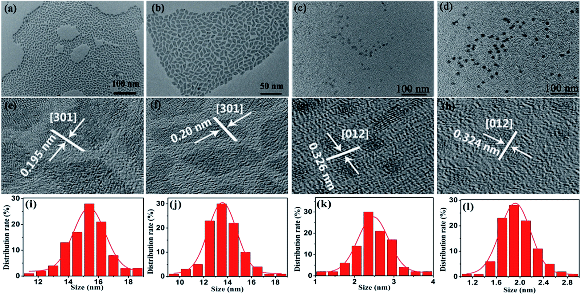
Fig. 1(a–d) show the morphology of UCNCs prepared at different OM/ODE ratios of 4:1, 3:2, 2:3 and 1:4. First, UCNCs are in uniform, monodisperse and rhombic shapes (Fig. 1(a and b)). The average side lengths of these NCs are 15.4 and 13.6 nm with a standard deviation of 1.0 nm (see Fig. 1(i and j)). The corresponding HR-TEM images of the lattice fringes with d-spacing of 0.195 nm and 0.20 nm are observed (Fig. 1(e and f)), which is in good agreement with the lattice spacing of the (301) planes of orthorhombic GdF3 (0.1961 nm, JCPDS: 12-0788). When the OM/ODE ratios was changed to 2:3 and 1:4, the UCNCs were transformed into spherical NCs with the smaller sizes of to 2.5 and 2.0 nm (Fig. 1(c, d, k and l)). Their lattice spacing was determined to 0.326 nm and 0.324 nm (Fig. 1(g and h)), which is according with the lattice spacing of the (012) planes of cubic GdOF (0.3161 nm, JCPDS: 50-0569). General trend of morphology and phases transition from rhombic shapes (GdF3) to spherical shapes (GdOF) as a function of OM/ODE ratios is shown in Fig. 2(a). In addition, the space structure of orthorhombic GdF3 and tetragonal GdOF are simulated, which belongs to the orthorhombic crystal system (a = 6.570 Å, b = 6.984 Å, c = 4.393 Å) and the cubic crystal system (a = 5.363 Å, b = 5.363 Å, c = 5.363 Å), respectively, as shown in Fig. 2(b and c). It should be noted that the Gd3+–Gd3+ distance in orthorhombic GdF3 NCs are 3.884 Å and 4.447 Å, which is longer than that of 3.792 Å in cubic GdOF NCs.33–36 The crystal structure's evolution was further monitored by tracking the changes in the UCNC's XRD patterns, as shown in Fig. 2(d and e). All the diffraction peaks can be exclusively indexed to orthorhombic GdF3 (Fig. 2(d)) and cubic GdOF (Fig. 2(e)), the peaks confirms the presence of highly crystalline GdF3 and GdOF NCs without impurity phases. In other words, the morphology and phase transforming between GdF3 and GdOF can be simultaneously controlled by adjusting the ratios between OM and ODE. The two-dimensional growth of the GdF3 rhombic nanoplates and the zero-dimensional growth of the GdOF spherical NCs are likely due to the selective adsorption of the capping ligands on specific crystal planes of NCs. The phase evolution between GdF3 and GdOF are more likely due to the different fluorination of the Gd–O bond to the Gd–F bond at the nucleation stage in different ratios of OM/ODE.37 The size, shape, and phase of UCNCs can also be affected by organic surfactant, reaction solvent, reaction temperature and the ionic radius of lanthanide ions.38,39 It should be noted most of NCs still retain uniformity and monodispersity after the morphology and phase transformation. And a small degree of agglomeration consisting of two or three NCs is happened (Fig. 1 (c and d)). Such agglomeration is usually observed in small NCs, due to the high activity of small NCs.
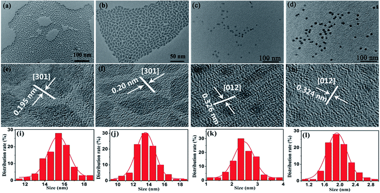 |
| | Fig. 1 (a–d) TEM images, (e–h) HR-TEM images, and (i–l) size distribution of GdF3:Yb3+,Tm3+ and GdOF:Yb3+,Tm3+ NCs synthesized at OM/ODE ratios of 4:1, 3:2, 2:3 and 1:4, respectively. | |
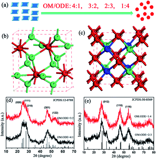 |
| | Fig. 2 (a) Schematic of morphology transition from rhombic shapes (GdF3) to spherical shapes (GdOF) as a function of OM/ODE ratios; (b and c) schematic of crystal phase structure orthorhombic GdF3 and cubic GdOF; (d and e) XRD patterns of GdF3:Yb3+,Tm3+ and GdOF:Yb3+,Tm3+ NCs prepared at OM/ODE ratios of 4:1, 3:2, 2:3 and 1:4, respectively. | |
3.2. Upconversion luminescence depending on defect state, crystal phase and size
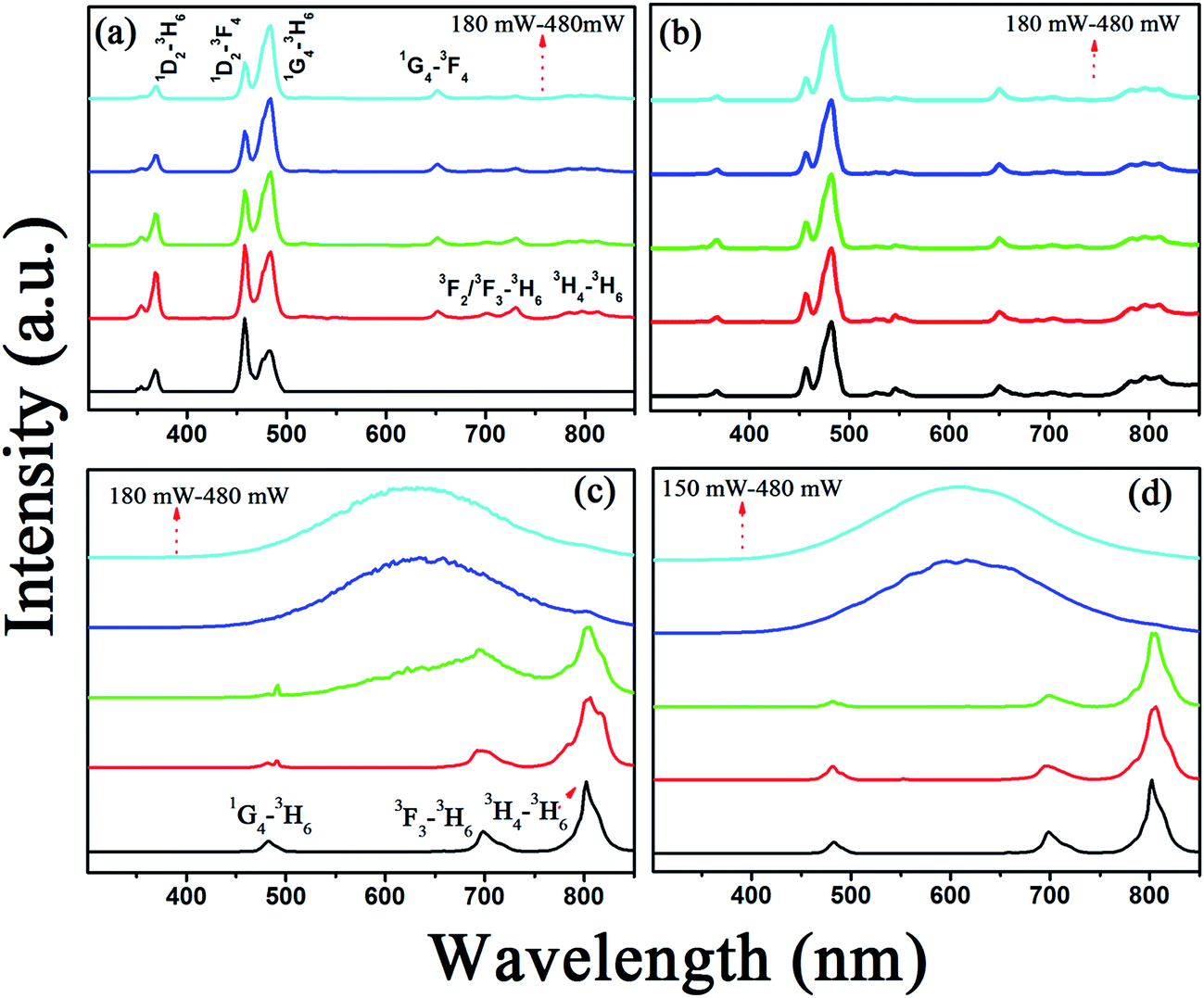
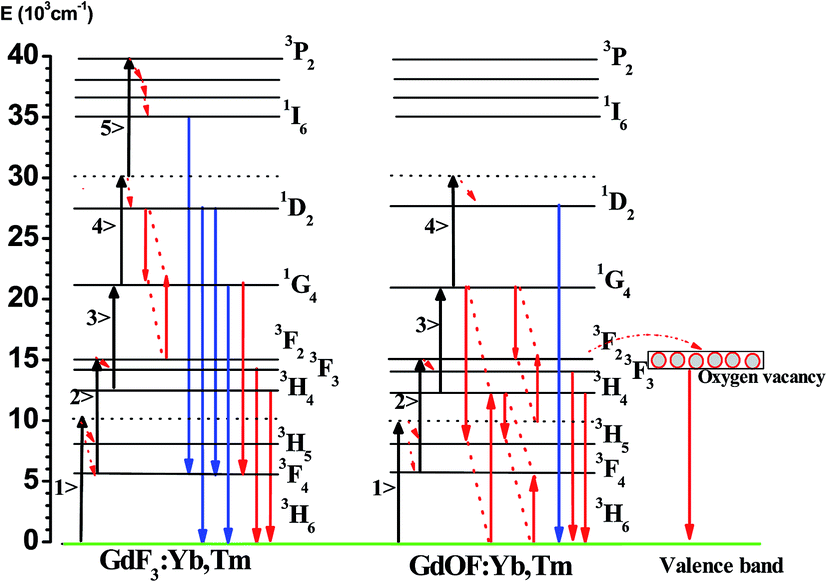
As known, the UCL properties of the RE-doped NCs strongly depend on their size, crystal structure, phonon energy, and defect states. In order to reveal the effect of the above elements on the UCL, the power-dependent spectra of GdF3:Yb3+,Tm3+ and GdOF:Yb3+,Tm3+ NCs are measured (see in Fig. 3(a–d)). As shown in Fig. 3(a and b), the typical UC multi-color emission of Tm3+ ions can be distinguished in GdF3:Yb3+,Tm3+ NCs, assigned to the 1D2–3H6 (368 nm), 1D2–3F4 (456 nm), 1G4–3H6 (480 nm), 1G4–3F4 (652 nm), 3F3–3H6 (700 nm) and 3H4–3H6 (800 nm) transitions, respectively. It should be noted that the dominant UC emission line locates in the blue region, centering at 480 nm. Interestingly, the luminescence intensity ratio of 1D2–3H6 + 3F4 to 1G4–3H6 transitions decreases with the increase of excitation power density in GdF3:Yb3+,Tm3+ NCs, which is opposite to the result observed in oxide host, such as NaGd(WO4)2:Yb3+,Tm3+ NCs,40 Tm3+/Yb3+ codoped water-free low silica calcium aluminosilicate glasses.41 This phenomenon can be attributed to the improved cross relaxation process of 1D2 + 1G4–3F3 + 1G4 with the increasing excitation power density, which can effectively increase the population of the 1G4 energy level.42
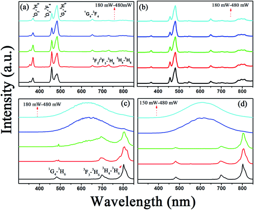 |
| | Fig. 3 UCL spectra of GdF3:Yb3+,Tm3+ and GdOF:Yb3+,Tm3+ NCs prepared at OM/ODE ratios of 4:1, 3:2, 2:3 and 1:4 with different 980 nm excitation power. | |
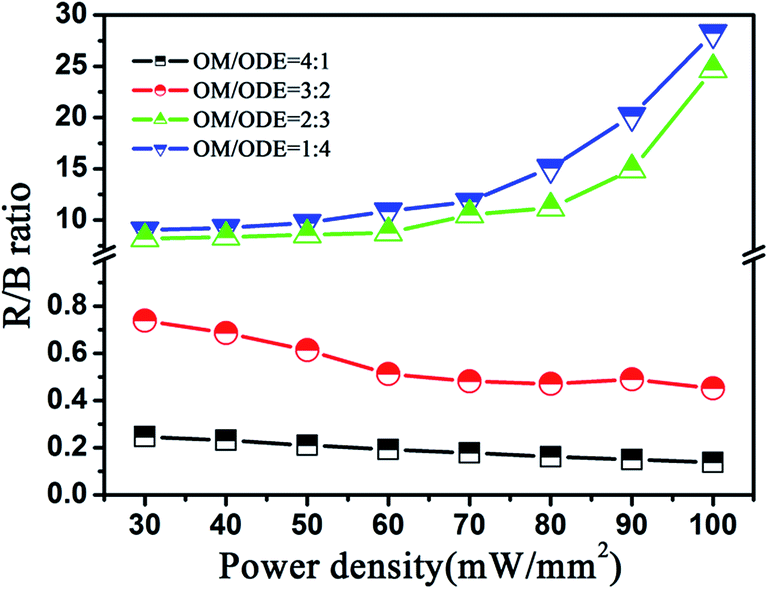
However, as the crystal structure transforms from GdF3 (Fig. 3(a and b)) to GdOF (Fig. 3(c and d)), the UC color changes from blue to red and the dominant emission in GdOF:Yb3+,Tm3+ NCs is assigned to 3H4–3H6 centering at 800 nm. The remarkable color change between GdF3:Yb3+,Tm3+ and GdOF:Yb3+,Tm3+ NCs could be attributed to the following reasons. First, the involving of oxygen defect states in GdOF host, which can increase non-radiative relaxation processes.43 For example, electrons on 3F2/3 can alternatively relax to the 3H4 intermediate state via the multi-phonon depopulation process, generating 3H4–3H6 (∼800 nm) transition, instead of populating from 3F2/3 to 1G4 level. Second, the crystal structure evolution from orthorhombic GdF3 to cubic GdOF results in shorter Gd3+–Gd3+ distance in cubic GdOF NCs (3.792 Å) relative to that in orthorhombic GdF3 NCs (3.884 Å and 4.447 Å), as shown in Fig. 2(b and c). Consequently, the doping of Yb3+ and Tm3+ ions into the GdOF host structure by substitution of Gd3+ cation creates closer Tm3+–Tm3+ pairs than those in GdF3 NCs lattices. The shorter distance between Tm3+–Tm3+ in GdOF NCs may improve the cross-relaxation processes (3H6 + 3H4–1G4 + 3H5, 3H6 + 3F4–3H4 + 3H5), possibly leading to the increase of the ratios of R/B (defines as the red emissions (3F3/3H4–3H6)/blue emissions (1D2–3H6/3F4, 1G4–3H6) ratios) in GdOF:Yb3+,Tm3+ NCs.44 Third, the size of UCNCs decreased from 15 nm to 2 nm with the crystal structure changed from GdF3 to GdOF, leading to lower crystallinity and more surface defects, which increase the ratio of nonradiative decay of luminescence centers, leading the increase of R/B.45
To better understand the multicolor tuning mechanism, the ratios (R/B) as a function of the excited power density are further studied, as shown in Fig. 4. In GdF3:Yb3+,Tm3+ NCs, the R/B ratios decreases gradually with the increase of the 980 nm excited power which is opposite to that observed in GdOF:Yb3+,Tm3+ NCs and traditional fluoride hosts.46 Generally, in some conventional fluoride samples (e.g. NaYF4:Yb, Er/Tm, YF3:Yb, Er/Tm), as the excitation density is high enough, the electron number of excited Er3+ or Tm3+ ions increases largely, inducing the increasing cross relaxation process, which effectively enhances the population at the 4F9/2 or 1G4/3H4 energy level of Er3+ or Tm3+ ions.47 Instead, the decrease of R/B ratios with excitation power in GdF3:Yb3+,Tm3+ NCs could be attributed to the competition between linear decay and upconversion processes for the depletion of the intermediate excited states, which was theoretically described by Pollnau et al.48
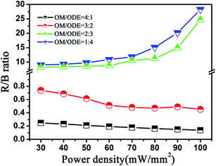 |
| | Fig. 4 R/B ratios of GdF3:Yb3+,Tm3+ and GdOF:Yb3+,Tm3+ NCs versus the 980 nm excitation power density. | |
3.3. Upconversion broad band emission in GdOF:Yb3+,Tm3+ NCs
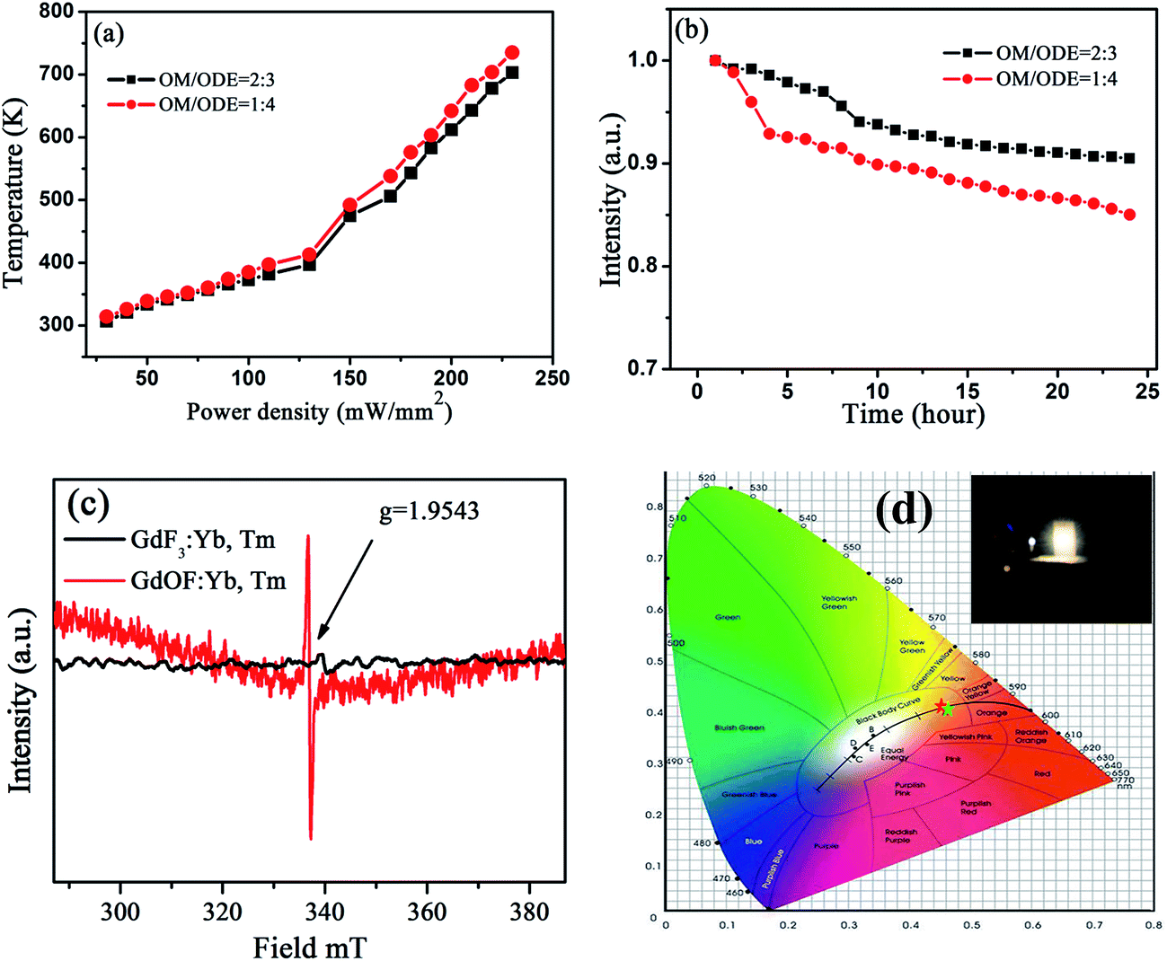
Interestingly, as the excitation power exceeded 540 mW mm−2 as shown in, a UC broad band emission in GdOF:Yb3+,Tm3+ NCs ranging of 450–750 nm appears and the emission intensity dramatically increases with increasing the excitation power, the step of increasing the excitation power density is 30 mW mm−2 (Fig. 3(c) and (d)). The central wavelength of these UC broadband emissions locates around 600 nm (∼2.1 eV) and is independent of excitation power. The temperature measurement under the exposure of 980 nm light was achieved by burying the thermocouple thermometer into the powder plate samples in Fig. 5(a). The threshold temperature for the UC broad band emission of GdOF:Yb3+,Tm3+ NCs prepared at OM/ODE ratios of 2:3 and 1:4 were 475 K and 492 K, which is much lower than the necessary temperature for generating sufficient blackbody radiation (∼2500 K).49 Thus, the broadband do not come from the blackbody radiation. And we also exclude that the present UC broad band originates from the charge transfer transition of Yb2+ or Yb3+ ions, because the charge transfer emissions of Yb2+ and Yb3+ located at around 560 nm and 650 nm (ref. 50) (different from 600 nm), the integral emission of broad band emission of GdOF:Yb3+,Tm3+ NCs was recorded every hour under the uninterrupted illumination of 980 nm (750 mW), as shown in Fig. 5(b). Its intensity reduces less than ∼15% over 24 h, which suggests that the broad band emission of GdOF:Yb3+,Tm3+ NCs has high photo-stability. In addition, the peak of UC broad band emission remains unaltered with increase of excitation power density and could be well fitted by a Gaussian function. Therefore, we deduce that UC broad band emission in GdOF:Yb3+,Tm3+ NCs originates form the UCL of oxygen defects.51 In order to further prove this, the electron paramagnetic resonance (EPR) spectra of GdF3:Yb3+,Tm3+ NCs and GdOF:Yb3+,Tm3+ NCs are recorded in Fig. 5(c). No EPR signal can be distinguished in GdF3:Yb3+,Tm3+ NCs, while in GdOF:Yb3+,Tm3+ NCs, a EPR signal is detected in the range of 0–800 mT with g factor of ∼1.9543. In general, when the actual measured g factor is lower than the free electron g factor (gfree = 2.0023), the EPR signal represents the electron trap.52 Accordingly, the EPR signal in GdOF:Yb3+,Tm3+ NCs should be assigned to the oxygen defects. Taken all together, as the excitation power is high enough, the temperature of GdOF:Yb3+,Tm3+ NCs samples increases considerably, leading to the cross relaxation (3F2/3 + 3F2/3–1G4 + 3H5) exacerbating (the super-strong power-dependence of the slopes (more than 10) further implies its happening, as shown in Fig. 7(c and d)). Then, most of the electrons on 3F2 might be captured by the oxygen vacancy states through the tunneling effect. The UC multicolor population and UC broad band emission mechanism in GdF3:Yb3+,Tm3+ and GdOF:Yb3+,Tm3+ NCs are presented in Fig. 6. Furthermore, we calculates the International Commission on Illumination (CIE) coordinates of the broad band emission in GdOF:Yb3+,Tm3+ NCs, which are (0.455, 0.406) and (0.466, 0.403) respectively, which both are located at white light region (shown in Fig. 5(d)). The inset of Fig. 5(d) shows a digital photograph of UC broad band emission of GdOF:Yb3+,Tm3+ excited 980 nm laser (750 mW). The bright white light can be seen clearly from the sample and the brightness is 5.3 × 10⁴ cd m−2, which has potential applications in white-light illumination.53
 |
| | Fig. 5 (a) Sample temperature as a function of 980 nm excitation power density in GdOF:Yb3+,Tm3+ NCs prepared at OM/ODE ratios of 2:3 and 1:4, (b) normalized integral intensity of UC broad band emissions in GdOF:Yb3+,Tm3+ NCs in this measuring period of 24 hours under the uninterrupted illumination of 980 nm laser (750 mW), (c) EPR spectra of GdF3:Yb3+,Tm3+ and GdOF:Yb3+,Tm3+ NCs at room temperature prepared at OM/ODE ratio of 4:1 and 1:4, (d) CIE chromaticity coordinates diagram of GdOF:Yb3+,Tm3+ NCs prepared at OM/ODE ratios of 2:3 and 1:4 under the excitation power of 750 mW from a 980 nm laser diode. Inset is the digital photograph of broadband emission of GdOF:Yb3+,Tm3+. | |
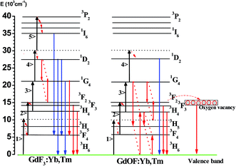 |
| | Fig. 6 Schematic of UCL populations and UC broadband mechanisms in Yb3+, Tm3+ co-doped GdF3 and GdOF samples under 980 nm excitation. | |
3.4. Power-dependence of UCL
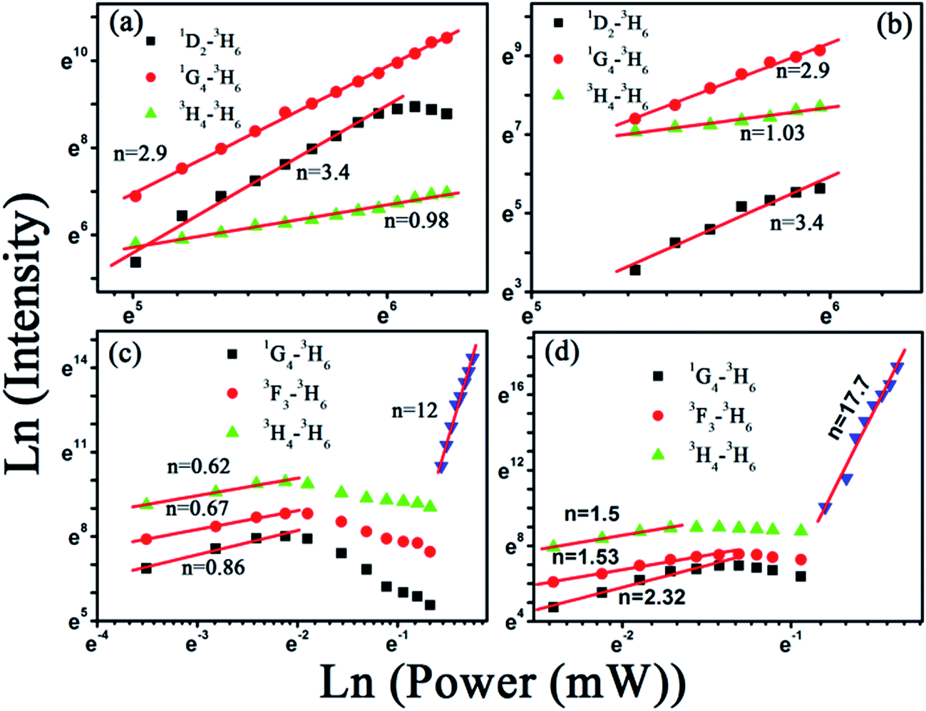
The visible output power intensity (IV) is proportional to power (n) of the infrared excitation (IIR) power if the saturation effect can be neglected:54
where n is the number of IR photons absorbed per visible photon emitted. The ln–ln plots of the emission intensity in GdF3:Yb3+,Tm3+ and GdOF:Yb3+,Tm3+ NCs as a function of excitation power for all the emissions levels are listed in Fig. 7. It is observed that the slopes of 1D2–3H6, 1G4–3H6, 3H4–3H6 in GdF3:Yb3+,Tm3+ NCs and 1G4–3H6, 3F3–3H6, 3H4–3H6 in GdOF:Yb3+,Tm3+ NCs are lower in different degree in comparison to the actual phonon numbers, and it is mainly due to the so-called saturation effect. The values of n for both the blue (1G4–3H6) and red (3F3, 3H4–3H6) emissions of Tm ions at the relatively low excitation power in the GdF3:Yb3+,Tm3+ NCs is larger than that in GdOF:Yb3+,Tm3+ NCs. In addition, in the GdF3:Yb3+,Tm3+ NCs, the UCL intensity increases continuously in the studied range, while in the GdOF:Yb3+,Tm3+ NCs, the quenching of UCL appears at a certain excitation power, which should be attributed to the thermal effect. Thermal effect is seriously affected by the phonon energy of the host. Because the phonon energy of GdOF (550 cm−1) is larger than that of GdF3 (320 cm−1), the thermal effect would be smaller in GdF3 NCs under the same power density excitation, leading to the smaller slopes in GdOF:Yb3+,Tm3+. We also observed that the slope of 3H4–3H6 transition is ∼1 in GdF3:Yb3+,Tm3+ NCs (shown in Fig. 7(a and b)). In the UC population process, if the linear decay is dominant, IV ∝ IIRn, otherwise, the UC is dominant, IV ∝ IIR.41 Therefore the UC is the dominant depletion mechanism of 3H4 level in GdF3:Yb3+,Tm3+ NCs, which is also in consistent with the decrease of R/B ratios with the increase of 980 nm excitation power (Fig. 4). Particularly, in Fig. 7(c and d), as the UC broadband emission appears, the UCL intensity increases dramatically with the increasing excitation power along with the slope reaching as high as 12 and 17.7, respectively. The super-strong power-dependence of the slopes (more than 10) implies that the UC broad band in GdOF:Yb3+,Tm3+ NCs might originate from a photon avalanche population process, instead of a traditional multiple-photon population process. Compared to the well known NaYF:Yb3+,Tm3+ (Er3+) nanocrystals (several nanometers) encountering the intensifying cross-relaxation or saturation effect under high power 980 nm excitation, UC broad band emission of GdOF:Yb3+,Tm3+ has better performance instead, which has the potential applications in a white light LED.
 |
| | Fig. 7 Plot (ln–ln) of emission intensity versus excitation power in (a and b) GdF3:Yb3+,Tm3+ and (c and d) GdOF:Yb3+,Tm3+ NCs prepared at different OM/ODE ratios of 4:1, 3:2, 2:3 and 1:4, respectively. | |
3.5. Dynamic processes in GdF3:Yb3+,Tm3+ and GdOF:Yb3+,Tm3+ NCs
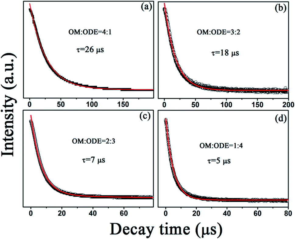
Fig. 8 shows the UCL dynamic curves of 1G4–3H6 transition in GdF3:Yb3+,Tm3+ and GdOF:Yb3+,Tm3+ NCs under 980 nm excitation with different ratios of OM/ODE, which can be well fitted to a single exponential function. It can be clearly seen that the decay time constants reduce from 26 to 5 μs with the change of the ratios of OM/ODE from 4:1 to 1:4, which can be attributed to the cooperative effect of the particle size, crystal phase, phonon energy and defects state. Firstly, as the particle size decreases, the number of detects and the large phonon bonds on the surface of the NCs increase due to the increase of the volume to surface ratio, leading the nonradiative relaxations (such as 1D2–1G4 and 1G4–3F2) to happen easily. Secondly, as known, in GdOF:Yb3+,Tm3+ NCs, the distance among Tm3+ ions decreases relative to that in GdF3:Yb3+,Tm3+ NCs, so the cross-relaxation process (such as 1G4 + 3H4–3F4 + 1D2, 3F2/3 + 3F2/3–1G4 + 3H5) among Tm3+ ions should be intensified in the UC population process. Thirdly, the larger phonon energy (550 cm−1) of GdOF:Yb3+,Tm3+ NCs leads the increase of the nonradiative relaxation processes via multiphonon assistant. The above factors result in the increase of nonradiative relaxation processes from excited states (e.g. 1D2, 1G4, 3F4 and 3H4 for Tm3+ ions) to defect states and/or large phonon bonds, leading to the decreasing of the decay time constants as well as the tuning of UC multicolor emissions.
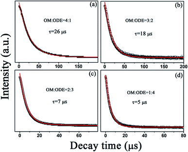 |
| | Fig. 8 UCL decay dynamics curves of the 1G4–3H6 transition at 480 nm of Tm3+ ions in (a and b) GdF3:Yb3+,Tm3+ and (c and d) GdOF:Yb3+,Tm3+ NCs prepared at different OM/ODE ratios of 4:1, 3:2, 2:3 and 1:4 under the 980 nm excitation. | |
4. Conclusions
In this research, we fabricated rhombic GdF3:Yb3+,Tm3+ and spherical GdOF:Yb3+,Tm3+ UCNCs using the thermolysis method. The effect of OM/ODE ratios on size, shape and multi-color tuning of lanthanide-ion doped UCNCs was studied in detail. The experimental results can be summarized as following. First, the UC emission color change from blue to red was observed with the transform of the crystalline phase from orthorhombic GdF3 to cubic GdOF NCs, which was mainly attributed to cooperative effect among crystal phase structure and size of UCNCs. Second, UC broadband emissions with super power-dependent lopes are observed in GdOF:Yb3+,Tm3+ under 980 nm laser illumination with high excitation power. Their origin could be oxygen vacancies, being accompanied by a photon avalanche population process. These UCNCs with broadband multi-color emissions are expected to find their applications in multi-color bio-imaging, white-light emitting diodes, and multiplexed cellular labeling.
Acknowledgements
This work was supported by National Natural Science Foundation of China (Grant no. 11504188, 11504131, 51374132), Natural Science Foundation of Henan Province (Grant no. U1504626), Science Foundation of Henan department of education of China (Grant no. 15A140011), the Open Fund of the State Key Laboratory On Integrated Optoelectronics (Grant no. 2015IOSKL KF31).
References
- F. Auzel, Chem. Rev., 2004, 104, 139 CrossRef CAS PubMed.
- W. Zheng, P. Huang, D. T. Tu, E. Ma, H. M. Zhu and X. Y. Chen, Chem. Soc. Rev., 2015, 44, 1379 RSC.
- R. R. Deng, F. Qin, R. F. Chen, W. Huang, M. H. Hong and X. G. Liu, Nat. Nanotechnol., 2015, 10, 237–242 CrossRef CAS PubMed.
- X. Zhang, P. P. Yang, Y. L. Dai, P. A. Ma, X. J. Li, Z. Y. Cheng, Z. Y. Hou, X. J. Kang, C. X. Li and J. Lin, Adv. Funct. Mater., 2013, 23, 4067–4078 CrossRef CAS.
- X. X. Hu, T. Wei, J. Wang, Z. E. Liu, X. Y. Li, B. H. Zhang, Z. H. Li, L. L. Li and Q. Yuan, Anal. Chem., 2014, 86, 10484–10491 CrossRef CAS PubMed.
- X. Y. Huang, S. Y. Han, W. Huang and X. G. Liu, Chem. Soc. Rev., 2013, 42, 173 RSC.
- B. Zhou, B. Y. Shi, D. Y. Jin and X. G. Liu, Nat. Nanotechnol., 2015, 10, 924–936 CrossRef CAS PubMed.
- Y. Q. Lu, J. B. Zhao, R. Zhang, Y. J. Liu, D. M. Liu, E. M. Goldys, X. S. Yang, P. Xi, A. Sunna, J. Lu, Y. Shi, R. C. Leif, Y. J. Huo, J. Shen, J. A. Piper, J. P. Robinson and D. Y. Jin, Nat. Photonics, 2014, 8, 32–36 CrossRef CAS.
- S. Lu, D. T. Tu, P. Hu, J. Xu, R. F. Li, M. Wang, Z. Chen, M. D. Huang and X. Y. Chen, Angew. Chem., Int. Ed., 2015, 54, 7915–7919 CrossRef CAS PubMed.
- J. B. Zhao, D. Y. Jin, E. P. Schartner, Y. Q. Lu, Y. J. Liu, A. V. Zvyagin, L. X. Zhang, J. M. Dawes, P. Xi, J. A. Piper, E. M. Goldys and T. M. Monro, Nat. Nanotechnol., 2013, 8, 729 CrossRef CAS PubMed.
- X. M. Li, Z. Z. Guo, T. C. Zhao, Y. Lu, L. Zhou, D. Y. Zhao and F. Zhang, Angew. Chem., Int. Ed., 2016, 55, 2464–2469 CrossRef CAS PubMed.
- O. Ehlert, R. Thomann, M. Darbandi and T. Nann, ACS Nano, 2008, 2, 120 CrossRef CAS PubMed.
- H. X. Mai, Y. W. Zhang, L. D. Sun and C. H. Yan, J. Phys. Chem. C, 2007, 111, 13721–13729 CAS.
- A. Nadort, J. B. Zhao and E. M. Goldys, Nanoscale, 2016, 8, 13099 RSC.
- J. Wang, H. W. Song, W. Xu, B. Dong, S. Xu, B. T. Chen, W. Yu and S. Zhang, Nanoscale, 2013, 5, 3412 RSC.
- A. Punjabi, X. Wu, A. Tokatli-Apollon, M. El-Rifai, H. Lee, Y. W. Zhang, C. Wang, Z. Liu, E. M. Chan, C. Y. Duan and G. Han, ACS Nano, 2014, 8, 10621–10630 CrossRef CAS PubMed.
- X. Teng, Y. H. Zhu, W. Wei, S. C. Wang, J. F. Huang, R. Naccache, W. B. Hu, A. I. YoongTok, Y. Han, Q. C. Zhang, Q. L. Fan, W. Huang, J. A. Capobianco and L. Huang, J. Am. Chem. Soc., 2012, 134, 8340–8343 CrossRef CAS PubMed.
- Z. E. Liu, J. Wang, Y. Li, X. X. Hu, J. W. Yin, Y. Q. Peng, Z. H. Li, Y. W. Li, B. M. Li and Q. Yuan, ACS Appl. Mater. Interfaces, 2015, 7, 19416–19423 CAS.
- F. Wang, R. R. Deng, J. Wang, Q. X. Wang, Y. Han, H. M. Zhu, X. Y. Chen and X. G. Liu, Nat. Mater., 2011, 10, 968–973 CrossRef CAS PubMed.
- J. F. Ren, G. H. Jia, Y. Y. Guo, A. X. Wang and S. Q. Xu, J. Phys. Chem. C, 2016, 120, 1342–1351 CAS.
- J. Wang, H. W. Song, W. Xu, B. Dong, S. Xu, B. T. Chen, W. Yu and S. Zhang, Nanoscale, 2013, 5, 3412 RSC.
- Y. Zhang, X. J. Li, D. L. Geng, M. M. Shang, H. Z. Lian, Z. Y. Cheng and J. Lin, CrystEngComm, 2014, 16, 2196 RSC.
- X. M. Li, F. Zhang and D. Y. Zhao, Chem. Soc. Rev., 2015, 44, 1346 RSC.
- I. F. Li, C. H. Su, H. S. Sheu, H. C. Chiu, Y. W. Lo, W. T. Lin, J. H. Chen and C. S. Yeh, Adv. Funct. Mater., 2008, 18, 766 CrossRef CAS.
- J. Zhou, M. X. Yu, Y. Sun, X. Z. Zhang, X. J. Zhu, Z. H. Wu, D. M. Wu and F. Y. Li, Biomaterials, 2011, 32, 1148 CrossRef CAS PubMed.
- B. K. Gupta, V. Rathee, T. N. Narayanan, P. Thanikaivelan, A. Saha, Govind, S. P. Singh, V. Shanker, A. A. Marti and P. M. Ajaya, Small, 2011, 13, 1767 CrossRef PubMed.
- Y. P. Du, Y. W. Zhang, L. D. Sun and C. H. Yan, J. Phys. Chem. C, 2008, 112, 405–415 CAS.
- M. M. Shang, G. G. Li, X. J. Kang, D. M. Yang, D. L. Geng, C. Peng, Z. Y. Cheng, H. Z. Lian and J. Lin, Dalton Trans., 2012, 41, 5571 RSC.
- L. Tao, W. Xu, Y. S. Zhu, L. Xu, H. C. Zhu, Y. X. Liu, S. Xu, P. W. Zhou and H. W. Song, J. Mater. Chem. C, 2014, 2, 4186 RSC.
- Q. Ju, Y. S. Liu, D. T. Tu, H. M. Zhu, R. F. Li and X. Y. Chen, Chem.–Eur. J., 2011, 17, 8549–8554 CrossRef CAS PubMed.
- J. E. Roberts, J. Am. Chem. Soc., 1961, 83, 1087 CrossRef CAS.
- Y. F. Wang, L. D. Sun, J. W. Xiao, W. Feng, J. C. Zhou, J. Shen and C. H. Yan, Chem.–Eur. J., 2012, 18, 5558–5564 CrossRef CAS PubMed.
- G. Q. Chai, G. P. Dong, J. R. Qiu, Q. Y. Zhang and Z. M. Yang, Sci. Rep., 2013, 3, 1598 Search PubMed.
- E. Talik, P. Zajdel, A. Guzik, D. Skrzypek, L. Lipńska and M. Michalska, J. Alloys Compd., 2014, 616, 556–568 CrossRef CAS.
- I. Levin, Q. Z. Huang, L. P. Cook and W. Wong-Ng, Eur. J. Inorg. Chem., 2005, 87, 91 Search PubMed.
- R. Q. Li, N. N. Zhang, L. L. Li, Y. M. Liang, Y. L. Liu and S. C. Gan, New J. Chem., 2015, 39, 7019 RSC.
- X. Sun, Y. W. Zhang, Y. P. Du, Z. G. Yan, R. Si, L. P. You and C. H. Yan, Chem.–Eur. J., 2007, 13, 2320–2332 CrossRef CAS PubMed.
- M. Haase and H. Schäfer, Angew. Chem., Int. Ed., 2011, 50, 5808–5829 CrossRef CAS PubMed.
- D. M. Liu, X. X. Xu, Y. Du, X. Qin, Y. H. Zhang, C. S. Ma, S. H. Wen, W. Ren, E. M. Goldys, J. A. Piper, S. X. Dou, X. G. Liu and D. Y. Jin, Nat. Commun., 2016, 7, 10254 CrossRef CAS PubMed.
- Y. F. Wang, W. Xu, S. B. Cui, S. Xu, Z. Yin, H. W. Song, P. W. Zhou, X. Y. Liu, L. Xu and H. N. Cui, Nanoscale, 2015, 7, 1363 RSC.
- C. Jacinto, M. V. D. Vermelho, E. A. Gouveia and M. T. Araujo, Appl. Phys. Lett., 2007, 91, 071102 CrossRef.
- X. Bai, D. Li, Q. Liu, B. Dong, S. Xu and H. W. Song, J. Mater. Chem., 2012, 22, 24698 RSC.
- C. M. Zhang and J. Lin, Chem. Soc. Rev., 2012, 41, 7938–7961 RSC.
- D. Li, B. Dong, X. Bai, Y. Wang and H. W. Song, J. Phys. Chem. C, 2010, 114, 8219–8226 CAS.
- W. B. Niu, S. L. Wu and S. F. Zhang, J. Mater. Chem., 2011, 21, 10894–10902 RSC.
- W. Yu, W. Xu, H. W. Song and S. Zhang, Dalton Trans., 2014, 43, 6139–6147 RSC.
- C. Y. Liu, Z. Y. Gao, J. F. Zeng, Y. Hou, F. Fang, Y. L. Li, R. R. Qiao, L. Shen, H. Lei, W. S. Yang and M. Y. Gao, ACS Nano, 2013, 7, 7227 CrossRef CAS PubMed.
- M. Pollnau, D. R. Gamelin, S. R. Lüthi, H. U. Güdel and M. P. Hehlen, Phys. Rev. B: Condens. Matter Mater. Phys., 2000, 61, 3337 CrossRef CAS.
- S. Redmond, S. C. Rand, X. L. Ruan and M. Kaviany, J. Appl. Phys., 2004, 95, 4069 CrossRef CAS.
- W. Strek, L. Marciniak, A. Bednarkiewicz, A. Lukowiak, R. Wiglusz and D. Hreniak, Opt. Express, 2011, 19, 14083 CrossRef CAS PubMed.
- Y. S. Zhu, W. Xu, S. B. Cui, M. Liu, C. Lu, H. W. Song and D. H. Kim, J. Mater. Chem. C, 2016, 4, 331 RSC.
- Y. Liu, S. L. Wan and X. G. Li, J. Phys.: Condens. Matter, 2007, 19, 196213 CrossRef.
- X. Bai, G. Caputo, Z. D. Hao, V. T. Freitas, J. H. Zhang, R. L. Longo, O. L. Malta, R. A. S. Ferreira and N. Pinna, Nat. Commun., 2014, 5, 5702 CrossRef CAS PubMed.
- Z. Wang, J. Feng, M. Pang, S. H. Pan and H. J. Zhang, Dalton Trans., 2013, 42, 12101 RSC.
|
| This journal is © The Royal Society of Chemistry 2017 |
Click here to see how this site uses Cookies. View our privacy policy here. 
 Open Access Article
 This Open Access Article is licensed under a
  ab,
Dongqin Bia,
Huiqiao Wanga,
Yinhua Wanga,
Xiumei Xua,
Zhiwen Lua and
Wen Xu*b
ab,
Dongqin Bia,
Huiqiao Wanga,
Yinhua Wanga,
Xiumei Xua,
Zhiwen Lua and
Wen Xu*b