 Open Access Article
Creative Commons Attribution 3.0 Unported Licence
Effect of Si content on structure and electrochemical performance of ternary nanohybrids integrating Si nanoparticles, N-doped carbon shell, and nitrogen-doped graphene†
Dehui Jia,
Zhiwei Yanga,
Lingling Xionga,
Honglin Luo*ab,
Guangyao Xionga,
Yong Zhuc and
Yizao Wan *ab
*ab
aSchool of Materials Science and Engineering, East China Jiaotong University, Nanchang 330013, China. E-mail: hlluotju@126.com; yzwantju@163.com; Fax: +86 22 2740 4724; Fax: +86 791 8704 6425; Tel: +86 22 2740 3045 Tel: +86 791 8704 6425
bSchool of Materials Science and Engineering, Tianjin University, Tianjin 300072, China
cSchool of Chemical Engineering, Tianjin University, Tianjin 300072, China
First published on 16th January 2017
Abstract
Hybridizing graphene with silicon (Si) is effective in developing high-performance Si-based anodes. However, the effect of Si content on the structure and electrochemical performance of these nanohybrids has not been extensively studied. Herein, a type of ternary Si/NC/NG nanohybrid with varying Si content was synthesized via a scalable, ecofriendly, and facile solution-mixing and carbonization process. In this nanostructure, Si nanoparticles were sheathed with N-doped carbon (NC) and the NC-wrapped Si nanoparticles were confined by nitrogen (N)-doped graphene (NG). The focus of this work was to determine how the Si content in the ternary nanohybrid affects its structure and electrochemical performance. SEM and TEM observations revealed that all Si nanoparticles were embedded in graphene nanosheets at low Si content while some aggregated and bare Si nanoparticles were observed at high Si content. Despite the simple preparation procedure, the ternary nanohybrid with an optimal Si content (83.9 wt%) delivered a high reversible capacity of 1210 mA h g−1 after 100 cycles at 0.5 A g−1, which outperforms most Si-based anodes in lithium-ion batteries (LIBs) reported so far. The findings presented in this paper represent a new criterion for the design of Si-based anodes with optimized electrochemical performance.
Lithium-ion batteries (LIBs) are very appealing power sources for electric vehicles since they can potentially meet the requirements of high energy density, high efficiency, and low emission simultaneously. However, the low capacity of conventional graphite-based anodes cannot meet the requirement of high energy density. Much effort has been devoted to the development of high-performance anode materials. To date, numerous anode materials with improved capacity have been developed, such as transition-metal oxides, silicon, and germanium,1–4 amongst which silicon (Si) is believed to be the most promising anode material for the next generation LIBs due to its high theoretical capacity (4200 mA h g−1), low discharge potential, relative abundance on the earth, and safety.1,5 However, using active materials alone is generally hard to fabricate high-performance anodes due to the huge volume variation during the repeated lithiation/delithiation process, which leads to the cracking and pulverization of the anodes, loss of electrical contact, and thus rapid capacity fading upon cycling.5,6 Another common problem with most active materials is their intrinsic low electrical conductivity. As a result, hybridizing active materials such as metal oxides and silicon, with conductive materials (mostly carbon nanotubes, graphene, and carbon nanofibers) has been regarded as one of the most effective approaches to improve their electrochemical performance.7–13 Among carbonaceous materials, graphene is the promising conductive substrate for the anchoring of various active materials in light of its excellent electrical conductivity, large surface area, and high physicochemical stability.14,15 Accordingly, up to now, various Si/graphene hybrids have been constructed and improved performance has been demonstrated. This hybridization of Si with graphene can effectively alleviate the stress caused by volume change16 and improve the conductivity of the Si anodes.
In order to further improve the performance of Si/graphene hybrids, efforts have been made to modify the structure of Si/graphene hybrids. One effective method is to introduce a carbon layer/shell on the surface of Si nanoparticles to circumvent the volume change problem. Numerous studies have demonstrated that carbon coating or incorporation can significantly improve the charge capacity and stability of the Si anodes thanks to the improved electrical conductivity and stress-buffer nature of carbon.17 Another strategy is to modify the structure of graphene nanosheets by, for example, nitrogen (N) doping. The N-doping into graphene has been believed to modulate the band structure of graphene, lead to a metal–semiconductor transition, alter the electronic performance, offer more active sites, and enhance the interaction between the carbon structure and lithium, thus improving the kinetics of lithium diffusion and transfer.18–20 For instance, reversible discharge capacity of N-doped graphene is almost doubled compared to pristine graphene due to the large number of surface defects induced by N-doping.21 Despite these advancements in the construction of carbon-coated Si nanoparticles and N-doping of graphene nanosheets, there is only one report about the simultaneous N-doping into the carbon shell on Si nanoparticles and the graphene nanosheets in the ternary nanohybrids.22 However, none of the previous studies have dealt with the effect of the content of Si nanoparticles on the electrochemical performance of Si/graphene hybrids.
Herein, as a continuum of our previous study,22 we demonstrate for the first time the effect of Si content on the structure and electrochemical performance of the ternary nanohybrids. The ternary nanohybrids were fabricated by a facile, scalable, and ecofriendly method of solution-mixing and carbonization. In the nanohybrids, Si nanoparticles with N-doped carbon shell (abbreviated as Si/NC) were confined by N-doped graphene (abbreviated as NG) nanosheets and the resultant nanohybrids are denoted as Si/NC/NG. Glucosamine was selected as the N-containing carbon precursor, which not only formed the N-containing carbon shell on the surface of Si nanoparticles, but also ensured the N-doping into graphene nanosheets. By doing so, we can take advantage of the following synergistic effects. First, the carbon shell on the surface of Si nanoparticles can effectively prevent direct contact between Si and the electrolytes, thereby preventing the electrolytes from decomposition. Second, the graphene wrapping around the Si/NC not only ensures good electrical contacts with Si nanoparticles but also acts as a flexible net, preventing the detachment of Si nanoparticles and accommodating the volume change. Third, the N-doping in carbon shell and graphene nanosheets can further enhance the electrical conductivity and increase the wettability23,24 of the nanohybrids to electrolyte. However, to realize our design concept, the Si content must be optimized to keep an integral and stable anode structure throughout the many charge and discharge cycles. It has been demonstrated that the content of Si nanoparticles affects the structure of Si/NC/NG nanohybrids. The Si/NC/NG nanohybrids with suitable Si contents exhibit high reversible capacities and excellent cycling performance and rate capability.
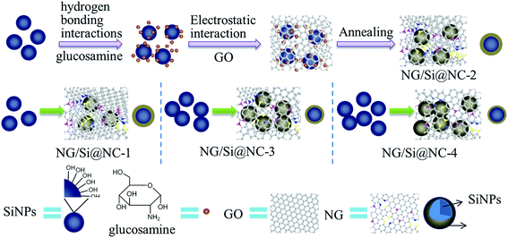
The Si/NC/NG nanohybrids were prepared via the solution-mixing and carbonization method. The detailed procedure, characterizations, and electrochemical measurements are presented in the ESI.† The overall preparation procedure for Si/NC/NG nanohybrids with varying Si content is schematically illustrated in Fig. 1. First, a thin layer of glucosamine was formed on the surface of Si nanoparticles via the hydrogen bonding interactions between –OH groups from glucosamine and the native oxide layer on Si nanoparticles. Subsequently, graphene oxide (GO) dispersion was added to the mixture of Si nanoparticles and glucosamine solution and glucosamine molecules are adsorbed onto the surface of GO nanosheets through the electrostatic interaction. In the subsequent thermal treatment of 800 °C in N2 flow, the glucosamine thin layer on Si nanoparticles was converted into N-doped carbon. The thermal treatment simultaneously reduced electrically insulated GO to conductive reduced graphene oxide and promoted the formation of NG through reactions between the released products and GO,25 giving rise to ternary Si/NC/NG nanohybrids where Si/NC nanoparticles were embedded in NG nanosheets. Obviously, as indicated by the arrows in the middle row of Fig. 1, the Si content can be controlled by the ratio of Si![[thin space (1/6-em)]](https://www.rsc.org/images/entities/char_2009.gif) :
:![[thin space (1/6-em)]](https://www.rsc.org/images/entities/char_2009.gif) glucosamine hydrochloride
glucosamine hydrochloride![[thin space (1/6-em)]](https://www.rsc.org/images/entities/char_2009.gif) :
:![[thin space (1/6-em)]](https://www.rsc.org/images/entities/char_2009.gif) GO.
GO.
Thermogravimetric analysis (TGA) was carried out in air and the result is presented in Fig. S1 (see in the ESI†) which reveals that the contents of Si in Si/NC/NG-1, Si/NC/NG-2, Si/NC/NG-3, and Si/NC/NG-4 are 57.5, 70.3, 83.9, and 89.2 wt%, respectively. The nanohybrids were also characterized by X-ray diffraction (XRD). XRD results (Fig. S2a†) indicate that no difference in the peak position and intensity can be found among these four samples and that all peaks in the XRD spectra can be indexed to Si. Fig. S2b† shows the magnified peak of NC/NG. Note that there is no obvious diffraction peaks corresponding to graphene and carbon in the XRD patterns, indicating that NG is evenly distributed in the nanohybrids without stacking or agglomeration26 and the NC is amorphous.
In order to determine the effect of N doping on the structure of carbon, we recorded the Raman spectra of Si/NC/NG-2 and the counterpart without N doping, named Si/C/G. The Raman results (Fig. S3a and b†) reveal the shift of D band from 1330 cm−1 for Si/C/G to 1342 cm−1 for Si/NC/NG-2 and G band from 1586 cm−1 to 1598 cm−1. The upshifts of D and G bands as a result of N-doping are due to the different bond distances of C–C and C–N, which cause the structural distortion of graphene and carbon and the formation of vacancy defects during the synthesis of NG and NC.
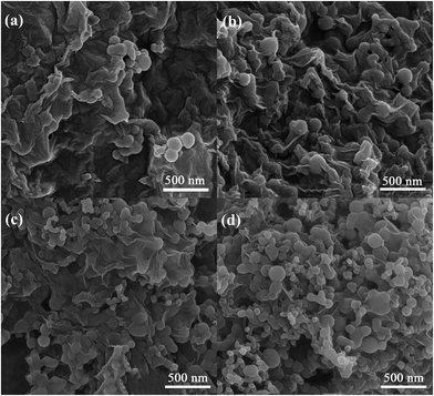
The morphology of Si/NC/NG nanohybrids was observed with SEM (Fig. 2). Fig. 2a and b demonstrate that the Si/NC nanoparticles are tightly enwrapped by graphene nanosheets that form interconnecting graphene networks in Si/NC/NG-1 and Si/NC/NG-2. It is expected that such a unique structure (i.e., electrochemically active Si/NC nanoparticles are confined within the graphene matrix) can effectively suppress the aggregation of Si/NC nanoparticles and enhance electrode stability against cycling processes for lithium storage. Compared to Si/NC/NG-2 that has a higher Si content, the contour of Si/NC particles in Si/NC/NG-1 is less obvious. As shown in Fig. 2c, Si/NC/NG-3 demonstrates similar morphology to Si/NC/NG-2, namely most Si/NC nanoparticles are confined in NG nanosheets with a few Si/NC nanoparticles that are not enwrapped. In the case of Si/NC/NG-4, however, a large portion of bare Si/NC nanoparticles are noted (Fig. 2d). Moreover, aggregation of Si/NC nanoparticles is also noted in Si/NC/NG-4. These findings suggest that the Si content affects the structure of Si/NC/NG nanohybrids and too much Si loading results in incomplete encapsulation of Si/NC nanoparticles by NG nanosheets.
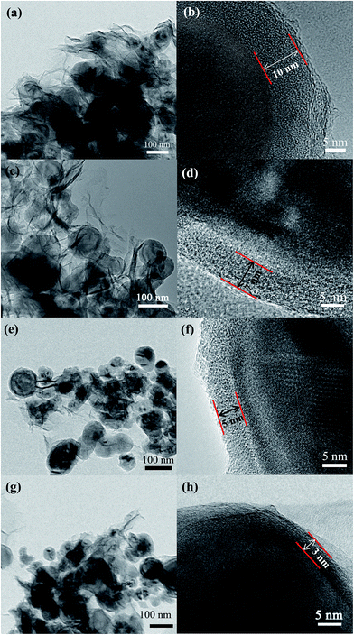
TEM was employed to further characterize these nanohybrids. Fig. 3a and c clearly shows the wrinkles of graphene and the entrapment of Si/NC nanoparticles in NG nanosheets for Si/NC/NG-1 and Si/NC/NG-2. The corresponding HRTEM reveals the existence of a carbon shell (with a thickness of around 10 and 7 nm for Si/NC/NG-1 and Si/NC/NG-2, respectively) on a single Si nanoparticle (Fig. 3b and d). As shown in Fig. 3e, Si/NC/NG-3 seems to have less amount of graphene wrapping the Si/NC nanoparticles compared with Si/NC/NG-1 and Si/NC/NG-2. HRTEM image in Fig. 3f demonstrates that the shell thickness on Si/NC in Si/NC/NG-3 is around 5 nm, which is smaller than that in Si/NC/NG-1 and Si/NC/NG-2. TEM image confirms the presence of un-wrapped Si/NC nanoparticles in Si/NC/NG-4 (Fig. 3g), consistent with SEM findings. HRTEM image (Fig. 3h) demonstrates that the thickness of carbon shell on Si/NC nanoparticles is only 3 nm for Si/NC/NG-4. This finding indicates that Si content also affects the thickness of carbon shell on Si/NC nanoparticles.
To verify the doping of N species, we chose a typical single NG-enwrapped Si/NC nanoparticle from Si/NC/NG-2 and conducted elemental mapping analysis (Fig. S4†). Evidently, Si element is distributed in the central area and C element, which is an indication of graphene and carbon shell, is uniformly distributed in the whole area. Interestingly, N element shows the same distribution as C element, suggesting the uniform doping of N species into graphene and carbon layer.
X-ray photoelectron spectra (XPS) analysis was conducted to probe binding configuration of N element in the nanohybrids. The results in Fig. S5† suggest the formation of different bonding structures in Si/NC/NG nanohybrids (the detailed analysis is presented in the ESI†).
The discharge–charge cycling was carried out in the voltage range of 0.01–1.5 V at a current density of 0.5 A g−1 for up to 100 cycles. Fig. 4 shows the first, second, 30th, 50th, and 100th charge–discharge curves of various Si/NC/NG anodes. In the first discharge curves of all samples, there is a plateau at around 0.1 V in the first cycle and then it disappears in the following cycles, indicating the formation of a stable SEI film on the electrode surface. As can be seen, Si/NC/NG-4 anode shows the highest initial charge/discharge capacity of 2674/3451 mA h g−1 at 0.1 A g−1, followed by Si/NC/NG-3 (2094/2744 mA h g−1), and then Si/NC/NG-2 (1142/1499 mA h g−1) and Si/NC/NG-1 (882/1182 mA h g−1), corresponding to initial coulombic efficiencies of 77.5%, 76.3%, 76.2%, and 74.6%, respectively. After the first cycle, the coulombic efficiency of Si/NC/NG-2 is higher than 97% in the second cycle and nearly 99% in the following cycles and the coulombic efficiency of Si/NC/NG-3 is 96% in the second cycle and over 98.5% from the 3rd cycle onward.
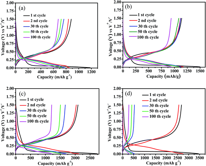 | ||
| Fig. 4 Charge and discharge curves of Si/NC/NG-1 (a), Si/NC/NG-2 (b), Si/NC/NG-3 (c), and Si/NC/NG-4 (d) obtained at the 1st, 2nd, 30th, 50th, and 100th cycles. | ||
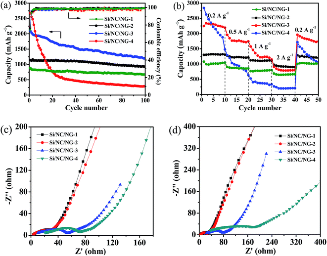
Fig. 5a shows the reversible capacities versus cycle number for four Si/NC/NG anodes. It is seen that Si/NC/NG-4 exhibits the worst cycling stability, with rapid capacity loss from an initial reversible capacity of 2674 mA h g−1 fading to 550 mA h g−1 after 30 cycles. The low capacity retention of Si/NC/NG-4 suggests that too much silicon content degrades cycling performance, consistent with a previous report.27 The rapid capacity loss is related to the following factors. On the one hand, the bare Si/NC nanoparticles without graphene wrapping account for the poor performance. These bare nanoparticles are not actively participating in the electrochemical reactions due to the absence of graphene nanosheets that serve to link the nanoparticles to the current collector. On the other hand, the thin carbon layer on Si nanoparticles is not sufficient to accommodate the huge volume change of Si nanoparticles, resulting in breaking of carbon shell and direct contact of Si nanoparticles with electrolytes, which causes continuous formation of unstable SEI. Note that Si/NC/NG-3 presents a very high capacity of 2094 mA h g−1 in the first cycle followed by a successive fading in capacity. Such gradual capacity loss with cycling number is common for Si-based anodes.17,28–35 Remarkably, after 100 cycles, a high capacity of 1210 mA h g−1 remains, which corresponds to 58% capacity retention after 100 cycles at 0.5 A g−1. Such high specific capacity indicates high accessibility of the active Si nanoparticles for Li insertion. The greatly improved capacity of Si/NC/NG-3 over Si/NC/NG-4 illustrates the importance of Si content in the hybrid systems. In the case of Si/NC/NG-2, an initial capacity of 1142 mA h g−1 is observed in the first cycle, which is significantly lower than that of Si/NC/NG-3. However, Si/NC/NG-2 shows more stable capacity and a higher capacity retention of 82% after 100 cycles. The high stability is due to the fact that all Si/NC nanoparticles in Si/NC/NG-2 are enwrapped by NG nanosheets that help to buffer the large volume changes and improve electronic conductivity in the electrode. It is interesting to note that Si/NC/NG-1 shows a lower initial capacity of 882 mA h g−1 due to its lower Si content than Si/NC/NG-2, indicating that sufficient Si content is necessary to obtain high reversible capacity. We can infer from these results that high Si content corresponds to high reversible capacity whereas abundant carbon/graphene network ensures high stability. A trade-off should be made between Si content and graphene network.
It should be pointed out that the reversible discharge capacity of 1210 mA h g−1 after 100 cycles at 0.5 A g−1 for Si/NC/NG-3 is superior to most previously reported Si-based electrodes.27,36–42 Although it is not as good as some Si-based electrodes,43–45 the preparation procedure is more facile, ecofriendly, and can be scaled up, which makes it more promising in future commercialization. The excellent cycling performance is ascribed to its structural advantages. First, all Si/NC nanoparticles are encircled by a N-doped carbon layer. The carbon layer not only restrains the Si nanoparticles from aggregating and improves the electrical conductivity of the Si anode, but also accommodates the volume expansion of Si and minimize the mechanical stress due to its stress-buffering role, thus improving the stability of the anode.1,46,47 The N-doping is believed to further improve the reversible capacity since it can induce a large number of topological defects on the carbon layer and form a disordered carbon structure, thus enhancing Li intercalation properties.18 Second, Si/NC nanoparticles are enwrapped by NG nanosheets. The role of graphene entrapment includes the buffering of the volume variation and enhancement of the conductivity.16,48 The N-doping into graphene can further enhance the capacity, surface wettability, and electrical conductivity of graphene.23,24
To test the effect of Si content on the rate performance of these ternary nanohybrids, the cells based on various Si/NC/NG anodes were measured for 50 cycles from 0.2 to 2 A g−1 in the voltage range of 0.01–1.5 V (Fig. 5b). Note that Si/NC/NG-4 possesses the worst rate capability and capacity retention among the Si/NC/NG nanohybrids. It delivers a capacity of 240 mA h g−1 at a rate of 2 A g−1 while the values for Si/NC/NG-1, Si/NC/NG-2, and Si/NC/NG-3 are 674, 975, and 912 mA h g−1, respectively. Importantly, although Si/NC/NG-3 has higher discharge capacity than Si/NC/NG-2, the latter shows better rate capability. When the current density turns back from 2 to 0.2 A g−1, the recovered capacities of Si/NC/NG-2 and Si/NC/NG-3 are 1291 and 1961 mA h g−1, showing retentions of 99 and 84%, respectively. This finding indicates that Si/NC/NG-2 has higher reversibility and better rate capability than Si/NC/NG-3. A number of studies have shown that the carbon layer reduces the capacity degradation of Si nanostructures by providing protection against many possible side reactions with the electrolyte.17 This has been confirmed by the thicker carbon layer of Si/NC/NG-2 compared to Si/NC/NG-3. Accordingly, the better rate capability of Si/NC/NG-2 as compared to Si/NC/NG-3 is attributed to its thicker carbon shell as well as more complete NG wrapping on Si/NC nanoparticles.
To better understand the influence of Si content, we performed electrochemical impedance spectroscopic (EIS) measurements on these samples. Fig. 5c and d shows the Nyquist plots of the cells with the Si/NC/NG nanohybrids as anodes. All EIS spectra exhibit a semicircle in the high/medium frequency region and an oblique straight line in the low frequency range. The intercept at the real (Z′) axis in the high frequency range indicates the ohmic resistance (Re), the semicircle in the middle frequency reflects the charge transfer resistance (Rct), and the inclined line in the low frequency region is attributable to the Warburg impedance (Zw). The Rct is a key indicator of the kinetics.49 The Rct of the electrodes before cycling and after rate capability measurements, as indicated by the diameter of the semicircle in the EIS spectra, decreases in the order of Si/NC/NG-4, Si/NC/NG-3, Si/NC/NG-2, and Si/NC/NG-1, confirming the highest ionic conductivity of Si/NC/NG-1. These results correlate well with their Si contents. Importantly, Si/NC/NG-4 has experienced the largest increment in Rct after rate capability tests, suggesting that it has the most unstable structure, which is consistent with its worst rate capability.
In summary, ternary Si/NC/NG nanohybrids with varying Si content have been fabricated via a facile, ecofriendly, and scalable process. We have found that the structure of the Si/NC/NG nanohybrids is highly dependent on the Si content in the nanohybrids. Too much Si leads to thinner carbon shell on Si nanoparticles and aggregated Si/NC nanoparticles, as well as non-entrapment of Si/NC nanoparticles by NG nanosheets. With the proper Si content, all Si nanoparticles are encircled by a layer of N-doped carbon and completely enwrapped by NG nanosheets. This unique structure enhances electron diffusion and conductivity of Si nanoparticles, accommodate Si expansion during lithiation and delithiation cycling, thus significantly improves the discharge capacity and cyclability. The Si/NC/NG-3 containing 83.9 wt% Si delivers the largest discharge capacity among the four nanohybrids while the Si/NC/NG-2 with a Si content of 70.3 wt% shows the best rate performance.
Acknowledgements
This work is supported by the National Natural Science Foundation of China (Grant no. 51572187 and 51563008) and the Science & Research Foundation of Jiangxi Province (Grant No. 20151BDH80061).Notes and references
- R. Zhang, Y. Du, D. Li, D. Shen, J. Yang, Z. Guo, H. K. Liu, A. A. Elzatahry and D. Zhao, Adv. Mater., 2014, 26, 6749–6755 CrossRef CAS PubMed.
- Y. Idota, T. Kubota, A. Matsufuji, Y. Maekawa and T. Miyasaka, Science, 1997, 276, 1395–1397 CrossRef CAS.
- P. Poizot, S. Laruelle, S. Grugeon, L. Dupont and J. Tarascon, Nature, 2000, 407, 496–499 CrossRef CAS PubMed.
- K. H. Seng, M. H. Park, Z. P. Guo, H. K. Liu and J. Cho, Angew. Chem., Int. Ed., 2012, 51, 5657–5661 CrossRef CAS PubMed.
- M. R. Zamfir, H. T. Nguyen, E. Moyen, Y. H. Lee and D. Pribat, J. Mater. Chem. A, 2013, 1, 9566–9586 CAS.
- D.-H. Nam, J. W. Kim, J.-H. Lee, S.-Y. Lee, S.-H. Lee and Y.-C. Joo, J. Mater. Chem. A, 2015, 3, 11021–11030 CAS.
- R. Epur, M. Ramanathan, M. K. Datta, D. H. Hong, P. H. Jampani, B. Gattu and P. N. Kumta, Nanoscale, 2015, 7, 3504–3510 RSC.
- H. Nguyen Trung, J. Suk, D. W. Kim, J. S. Park and Y. Kang, J. Mater. Chem. A, 2014, 2, 15094–15101 Search PubMed.
- W. Wang, I. Ruiz, K. Ahmed, H. H. Bay, A. S. George, J. Wang, J. Butler, M. Ozkan and C. S. Ozkan, Small, 2014, 10, 3389–3396 CrossRef CAS PubMed.
- B. Xu, H. Wu, C. X. Lin, B. Wang, Z. Zhang and X. S. Zhao, RSC Adv., 2015, 5, 30624–30630 RSC.
- M. Srivastava, J. Singh, T. Kuila, R. K. Layek, N. H. Kim and J. H. Lee, Nanoscale, 2015, 7, 4820–4868 RSC.
- J. Zai and X. Qian, RSC Adv., 2015, 5, 8814–8834 RSC.
- J. Lee, C. Jo, B. Park, W. Hwang, H. I. Lee, S. Yoon and J. Lee, Nanoscale, 2014, 6, 10147–10155 RSC.
- Z.-S. Wu, G. Zhou, L.-C. Yin, W. Ren, F. Li and H.-M. Cheng, Nano Energy, 2012, 1, 107–131 CrossRef CAS.
- M. Pumera, Chem. Soc. Rev., 2010, 39, 4146–4157 RSC.
- B. Wang, X. Li, X. Zhang, B. Luo, M. Jin, M. Liang, S. A. Dayeh, S. Picraux and L. Zhi, ACS Nano, 2013, 7, 1437–1445 CrossRef CAS PubMed.
- Y. J. Cho, H. S. Kim, H. Im, Y. Myung, G. B. Jung, C. W. Lee, J. Park, M.-H. Park, J. Cho and H. S. Kang, J. Phys. Chem. C, 2011, 115, 9451–9457 CAS.
- H. Wang, C. Zhang, Z. Liu, L. Wang, P. Han, H. Xu, K. Zhang, S. Dong, J. Yao and G. Cui, J. Mater. Chem., 2011, 21, 5430–5434 RSC.
- D. Wei, Y. Liu, Y. Wang, H. Zhang, L. Huang and G. Yu, Nano Lett., 2009, 9, 1752–1758 CrossRef CAS PubMed.
- Y. Wang, Y. Shao, D. W. Matson, J. Li and Y. Lin, ACS Nano, 2010, 4, 1790–1798 CrossRef CAS PubMed.
- A. L. M. Reddy, A. Srivastava, S. R. Gowda, H. Gullapalli, M. Dubey and P. M. Ajayan, ACS Nano, 2010, 4, 6337–6342 CrossRef CAS PubMed.
- D. Ji, Y. Wan, Z. Yang, C. Li, G. Xiong, L. Li, M. Han, R. Guo and H. Luo, Electrochim. Acta, 2016, 192, 22–29 CrossRef CAS.
- X. Li, H. Wang, J. T. Robinson, H. Sanchez, G. Diankov and H. Dai, J. Am. Chem. Soc., 2009, 131, 15939–15944 CrossRef CAS PubMed.
- J. Xu, M. Wang, N. P. Wickramaratne, M. Jaroniec, S. Dou and L. Dai, Adv. Mater., 2015, 27, 2042–2048 CrossRef CAS PubMed.
- X. Fan, C. Yu, J. Yang, Z. Ling and J. Qiu, Carbon, 2014, 70, 130–141 CrossRef CAS.
- Y. Yao, J. Qin, Y. Cai, F. Wei, F. Lu and S. Wang, Environ. Sci. Pollut. Res., 2014, 21, 7296–7306 CrossRef CAS PubMed.
- J. Park, G.-P. Kim, I. Nam, S. Park and J. Yi, Nanotechnology, 2013, 24, 025602 CrossRef PubMed.
- H. Kim and J. Cho, Nano Lett., 2008, 8, 3688–3691 CrossRef CAS PubMed.
- L.-F. Cui, Y. Yang, C.-M. Hsu and Y. Cui, Nano Lett., 2009, 9, 3370–3374 CrossRef CAS PubMed.
- C. K. Chan, R. N. Patel, M. J. O'Connell, B. A. Korgel and Y. Cui, ACS Nano, 2010, 4, 1443–1450 CrossRef CAS PubMed.
- H. Wang, P. Wu, H. Shi, F. Lou, Y. Tang, T. Zhou, Y. Zhou and T. Lu, Mater. Res. Bull., 2014, 55, 71–77 CrossRef CAS.
- Y. Wang, X. Wen, J. Chen and S. Wang, J. Power Sources, 2015, 281, 285–292 CrossRef CAS.
- M.-S. Wang, W.-L. Song, J. Wang and L.-Z. Fan, Carbon, 2015, 82, 337–345 CrossRef CAS.
- W. Wang, Y. Wang, L. Gu, R. Lu, H. Qian, X. Peng and J. Sha, J. Power Sources, 2015, 293, 492–497 CrossRef CAS.
- C. Xiao, N. Du, X. Shi, H. Zhang and D. Yang, J. Mater. Chem. A, 2014, 2, 20494–20499 CAS.
- J. J. Kochumalayil, M. Bergenstrahle-Wohlert, S. Utsel, L. Wagberg, Q. Zhou and L. A. Berglund, Biomacromolecules, 2013, 14, 84–91 CrossRef CAS PubMed.
- J. Lai, H. Guo, Z. Wang, X. Li, X. Zhang, F. Wu and P. Yue, J. Alloys Compd., 2012, 530, 30–35 CrossRef CAS.
- M. Dirican, M. Yanilmaz, K. Fu, O. Yildiz, H. Kizil, Y. Hu and X. Zhang, J. Electrochem. Soc., 2014, 161, A2197–A2203 CrossRef CAS.
- K. Fu, Y. Lu, M. Dirican, C. Chen, M. Yanilmaz, Q. Shi, P. D. Bradford and X. Zhang, Nanoscale, 2014, 6, 7489–7495 RSC.
- M. Su, Z. Wang, H. Guo, X. Li, S. Huang, L. Gan and W. Xiao, Powder Technol., 2013, 249, 105–109 CrossRef CAS.
- H. Bai, F. Walsh, B. Gludovatz, B. Delattre, C. Huang, Y. Chen, A. P. Tomsia and R. O. Ritchie, Adv. Mater., 2015, 28, 50–56 CrossRef PubMed.
- M. S. Wang, W. L. Song and L. Z. Fan, ChemElectroChem, 2015, 2, 1699–1706 CrossRef CAS.
- S. A. Klankowski, G. P. Pandey, B. A. Cruden, J. Liu, J. Wu, R. A. Rojeski and J. Li, J. Power Sources, 2015, 276, 73–79 CrossRef CAS.
- J. S. Kim, W. Pfleging, R. Kohler, H. J. Seifert, T. Y. Kim, D. Byun, H.-G. Jung, W. Choi and J. K. Lee, J. Power Sources, 2015, 279, 13–20 CrossRef CAS.
- Y. Xu, Y. Zhu, F. Han, C. Luo and C. Wang, Adv. Energy Mater., 2015, 5(1), 1400753 CrossRef.
- J. Saint, M. Morcrette, D. Larcher, L. Laffont, S. Beattie, J. P. Pérès, D. Talaga, M. Couzi and J. M. Tarascon, Adv. Funct. Mater., 2007, 17, 1765–1774 CrossRef CAS.
- Z. Guo, D. Jia, L. Yuan and H. Liu, J. Power Sources, 2006, 159, 332–335 CrossRef CAS.
- J. Chang, X. Huang, G. Zhou, S. Cui, P. B. Hallac, J. Jiang, P. T. Hurley and J. Chen, Adv. Mater., 2014, 26, 758–764 CrossRef CAS PubMed.
- C. Chen, J. Liu and K. Amine, J. Power Sources, 2001, 96, 321–328 CrossRef CAS.
Footnote |
| † Electronic supplementary information (ESI) available. See DOI: 10.1039/c6ra26994j |
| This journal is © The Royal Society of Chemistry 2017 |

