 Open Access Article
Creative Commons Attribution 3.0 Unported Licence
Iron–nitrogen co-doped hierarchically mesoporous carbon spheres as highly efficient electrocatalysts for the oxygen reduction reaction†
You-Lin Liu‡
,
Xue-Yan Xu‡,
Cheng-Xiang Shi,
Xin-Wei Ye,
Ping-Chuan Sun and
Tie-Hong Chen *
*
Institute of New Catalytic Materials Science, School of Materials Science and Engineering, Key Laboratory of Advanced Energy Materials Chemistry (MOE), Collaborative Innovation Centre of Chemical Science and Engineering (Tianjin), Nankai University, Tianjin 300350, PR China. E-mail: chenth@nankai.edu.cn
First published on 27th January 2017
Abstract
By using hierarchically mesoporous silica spheres as hard template, 2-aminopyridine and FeCl3 as carbon, nitrogen and iron sources, respectively, iron and nitrogen co-doped hierarchically mesoporous carbon spheres (Fe–N–CS) were successfully prepared. The sample Fe–N–CS-900 obtained at a carbonization temperature of 900 °C exhibited a highly efficient electrocatalytic activity with positive half-wave potential (−0.11 V), high limiting current density (−4.79 mA cm−2) and high selectivity (electron transfer number around 4) for the oxygen reduction reaction (ORR) in alkaline media. Moreover, Fe–N–CS-900 shows higher stability and better methanol tolerance in comparison to commercial Pt/C catalyst in both alkaline and acidic media. Its highly efficient ORR activity could be ascribed to its high specific surface area, unique porous structure and homogeneous distribution of Fe–Nx active sites formed during pyrolysis.
Introduction
The oxygen reduction reaction (ORR) plays an important role in various energy storage and conversion process, such as fuel cells and metal–air batteries.1,2 Although platinum-based materials are the best ORR catalysts,3,4 they suffer from slow reduction kinetics, high cost, low stability and the crossover effect, which are drawbacks for large-scale commercialization. Therefore, exploring non-precious metal (NPM)5–10 and metal-free11–15 catalysts with excellent ORR activity and high stability has been attracting extensive interest. Various nitrogen-doped carbons16–19 and carbon-supported transition metal oxides (Fe, Co, Mn)20–24 have been reported, and these catalysts exhibited an obviously high ORR activity in alkaline media. Unfortunately, in acidic solution most of the nitrogen doped carbon materials had little electrocatalytic activity and lower stability due to the protonation of doped nitrogen active sites,25,26 and carbon-supported transition metal oxide catalysts could not be used in acidic media.Recently, nitrogen doping and transitional metal-contained carbon materials, particularly, Fe (or Co)–Nx/C have been recognized as the most promising NPM catalysts for ORR in both alkaline and acidic media.27–31 It is found that Fe (or Co)–Nx sites are attributed to the main active sites for ORR. Thus, various methods have being used to improve active sites density of M–Nx/C materials. Traditionally, M–Nx/C catalysts are prepared by the direct pyrolysis of the mixture of nitrogen precursor, transitional metal and carbon precursor. However this method frequently fails to control the contribution and density of transition metal–nitrogen active sites, leading to relatively poor catalytic performance.32
Catalysts with mesoporous structure generally possess high surface area and large pore volume, which not only facilitate the exposure of active sites and benefit the mass transport of intermediate species, but also lead to enhanced electron delivery due to the continuous framework structure.20,33 Mesoporous carbon catalysts prepared by template methods, e.g. mesoporous metal–nitrogen-doped carbons,34 ordered mesoporous porphyrin-based carbon materials,35,36 and ordered mesoporous Fe–N carbons,37 have been reported to enhance the electrocatalytic activity of ORR. Furthermore, hierarchically porous carbon materials co-doped with iron and nitrogen exhibited excellent performance for ORR.38–40
Herein we report preparation of iron and nitrogen co-doped hierarchically mesoporous carbon spheres by using hierarchically mesoporous silica spheres as hard template, high nitrogen content monomer (2-aminopyridine) as carbon and nitrogen sources, and FeCl3 as iron source. It is proved that both the Fe–Nx active sites and porous structure are very helpful to ORR activity and the carbon spheres exhibited higher stability and better methanol tolerance in comparison to commercial Pt/C catalyst in both alkaline and acidic media.
Experimental
Synthesis of hierarchically mesoporous silica sphere template
Hierarchically mesoporous silica spheres (HMS) were synthesized following our previously reported method.41 First, 0.55 g CTAB was dissolved in 25.0 mL of distilled water, and 3.0 g PAA (25%) was added under vigorous stirring at room temperature to obtain a clear solution. Then 2.0 g ammonia (25%) was added to the above solution under vigorous stirring. After 20 min stirring, 2.08 g tetraethoxysilane (TEOS) was added to the above solution and continued stirring for 15 min, the mixture was transferred into an autoclave, which was put into an oven of 100 °C for 48 h. The final product was centrifugated, washed with distilled water, and dried at 60 °C. The organic templates were removed by calcination at 550 °C for 6 h.Synthesis of porous carbon spheres
In a typical synthesis of iron–nitrogen co-doped hierarchically mesoporous carbon spheres (denoted as Fe–N–CS-T, T: carbonization temperature), 1.2 g HMS template were stirred in toluene solution containing 1.43 g 2-aminopyridine, after stirring for 10 min, 3.45 g ammonium persulphate and 0.82 g FeCl3·6H2O were added to above mixture solution and the resultant mixture were stirred for 12 h in an ice bath (0–10 °C). This led to polymerization of 2-aminopyridine, after polymerization, the obtained mixture solution was centrifugated and the solid powder was dried at 120 °C for 12 h, finally the brown solid powder precursors were obtained. Then the precursors were pyrolyzed at different temperature (700–1000 °C) in a flow of high-purity N2 atmosphere. After removal silica by HF (20 wt%) etching, Fe–N–CS-T samples were obtained. For comparison, Fe-free samples (N–CS-T) were obtained without adding FeCl3 during the polymerization process.Characterization
Field-emission scanning electron microscopy (FESEM; JEOL, JSM-7500F, 8 kV) was used to analyze the morphology of the prepared samples. Transmission electron microscopy (TEM) was performed on a Philips Tecnai F20 microscope, working at 200 kV. All samples subjected to TEM measurements were dispersed in ethanol ultrasonically and were dropped on copper grids. Raman spectra were examined with a LabRAM HR Raman spectrometer using laser excitation at 514.5 nm. Powder X-ray diffraction (XRD) patterns were recorded on a D/max-2500 diffractometer (Rigaku, Japan) using Cu Kα radiation (λ = 1.5406 Å). XPS spectra were obtained with a Kratos Axis Ultra DLD spectrometer. Nitrogen adsorption and desorption isotherms were measured on a BELSORP-mini II sorption analyser at 77 K.Electrochemical measurements
Electrochemical experiments were conducted at room temperature on a CHI660D electrochemical workstation. A three-electrode system including a glassy carbon rotating disk electrode (RDE) coated with catalysts, a platinum wire auxiliary electrode and a KCl (3 M) Ag/AgCl reference electrode. For electrode preparation, 2 mg sample was dispersed in 1 mL of H2O by sonication for 30 min at least. Then 20 μL of the resulting homogeneous suspension was carefully dropped with pipette onto a rotation disk electrode (RDE), which was air-dried to allow solvent evaporation. After drying at room temperature, 3 μL of 5 wt% Nafion solution was further dropped to form a protection layer against catalyst detaching from the electrode surface. The catalyst loading was 0.41 mg cm−2 in alkaline media. High-purity N2 or O2 was purged for 30 min at least before each test. For comparison, the benchmark commercial Pt/C (20 wt% Pt on VXC-72) catalyst was also fabricated into electrodes through similar procedure, with the loading of 62 μg Pt per cm2 in alkaline media. For ORR in acidic media, 0.5 M H2SO4 solution and 0.1 M HClO4 solution were used as electrolytes for Koutecky–Levich analysis of the prepared catalysts (0.62 mg cm−2) and Pt/C catalyst (41 μg Pt per cm2), respectively.Results and discussion
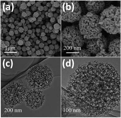
The procedure for synthesis of the Fe–N co-doped carbon spheres is illustrated in Scheme 1. A high nitrogen content monomer (2-aminopyridine) first entered into the mesopores of silica spheres, and then in situ oxidation polymerization reaction was performed in the mesopores. The obtained precursors polymer within the mesopores of silica template (polymer/SiO2) were dried and then pyrolyzed at different temperature (700–1000 °C) under flowing high-purity nitrogen atmosphere, the black power was obtained. Finally, the samples (Fe–N–CS-T) were obtained by removing silica templates.The morphology and structure of Fe–N–CS-900 were characterized by scanning electron microscopy (SEM) and transition electron microscopy (TEM). Fig. 1a and b showed Fe–N–CS-900 was composed of well-defined carbon spheres with rough surface, which successfully copied the morphology of mesoporous template (Fig. S1†). TEM (Fig. 1c and d) indicated the carbon spheres were three-dimensional connected porous framework structure. These observations well reflected the geometric characteristic of the original template, suggesting successful preparation of porous carbon spheres.
The porosity of Fe–N–CS-T was analyzed by N2 adsorption isotherms (Fig. 2, S2 and Table S1†). Fe–N–CS-900 exhibited a type IV isotherm with three adsorption steps at the relative pressure of 0.01–0.1, 0.20–0.70, and 0.80–0.95, respectively. The first step corresponded to the micropores within the carbon matrix. The second adsorption gave rise to a pore size distribution at about 2–3 nm (Fig. 2b), which was ascribed to the small disordered mesopores. The third adsorption step gave rise to a peak at about 25 nm in the pore size distribution curve, corresponding to larger mesopores (Fig. 2b). Table S1† showed that Fe–N–CS-900 exhibited highest specific surface area of 758 m2 g−1 and large pore volume of 1.59 cm3 g−1. In order to investigate the formation of mesopores, the pyrolyzed sample (denoted Fe–N–CS/SiO2-900) without removal of the silica template was shown in Fig. 2a, nitrogen adsorption–desorption isotherms of Fe–N–CS/SiO2-900 showed it had little mesoporous structure. This results indicated that most of mesoporous structure of Fe–N–CS-900 was derived from the hierarchically mesoporous silica template.
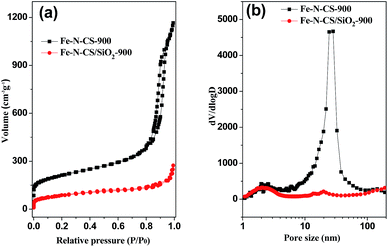 | ||
| Fig. 2 (a) Nitrogen adsorption–desorption isotherms of Fe–N–CS-900, Fe–N–CS/SiO2-900 and (b) their corresponding pore size distribution curve. | ||
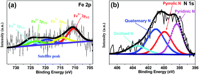
X-ray photoelectron spectroscopy (XPS) was performed to analyze the content and the chemical state for the surface doping elements in the samples (Fig. 3 and S3†). Fig. S3† showed Fe–N–CS-900 had four kinds of elements, carbon, oxygen, nitrogen (4.53 wt%) and iron (0.83 wt%). N 1s spectrum of Fe–N–CS-900 catalyst (Fig. 3b) could be divided into four peaks at 398.4 eV, 400.0 eV, 401.0 eV and 403.4 eV,42,43 which were assigned to pyridinic N (27.57%), pyrrolic N (26.39%), graphitic N (33.64%) and pyridinic N–O (12.41%). The graphitic N played a crucial role in oxygen reduction;19 the pyridinic N and pyrrolic N could serve as metal-coordination sites29,38 and these three different nitrogen species were of high content in Fe–N–CS-900, which may lead to high ORR activity. The Fe 2p XPS spectrum of Fe–N–CS-900 (Fig. 3a) was deconvoluted into five different peaks, indicating that iron species in the catalyst were complicated in terms of its metallic state. According to previous reports,28,38 the Fe 2p peaks at 711.3 eV were ascribed to the nitrogen-coordinated metal, which were dominated iron species in Fe–N–CS-900 catalyst. In addition, elemental mapping (Fig. 4) imaging revealed that both iron and nitrogen species were homogeneous distributed in the mesoporous carbon spheres. The bright areas in Fig. 4b–d were likely due to differences in carbon thickness in the sample.
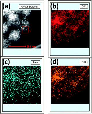 | ||
| Fig. 4 (a) STEM image of Fe–N–CS-900, (b) carbon-, (c) iron- and (d) nitrogen-elemental mapping of square region 1. | ||
Although there was an amount of iron species in Fe–N–CS-900 sample. We hardly observed any metal nanoparticles in the carbon structure by TEM (Fig. 1d). Power X-ray diffraction pattern (PXRD) further indicated the absence of the crystalline metal or metal oxide nanoparticles and showed only the partially graphitized carbon (Fig. S4†). The Raman spectrum (Fig. S5†) showed a typical D-band at 1375 cm−1 and a G-band at 1590 cm−1 indicating co-existence of amorphous and graphitic structures.
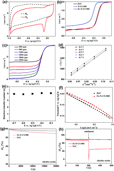
Cyclic voltammetry (CV) in N2 and O2-saturated 0.1 M KOH solution was first evaluated to examine ORR activity for Fe–N–CS-T catalysts. Fig. 5a showed that in N2-saturated KOH solution CV curve of Fe–N–CS-900 exhibited the featureless characteristic, indicating negligible redox reaction and inertness on the carbon surface. In contrast, when the electrolyte was saturated with O2, there is a sharp electrochemical reduction peak (peak potentials at −0.11 V), which was more positive than those of nitrogen-doped carbon spheres,44,45 suggesting the pronounced catalytic activity of Fe–N–C-900 catalyst for ORR in an alkaline solution. Fig. S6† showed that the optimal temperature was 900 °C, as revealed by the most positive peak potential and higher peak current density in the CV curves, probably due to an appropriate balance of surface area, active site density, and graphitization degree at this temperature (Table S1, Fig. S4 and S5†). Therefore, the prepared catalysts discussed below were all produced at 900 °C unless otherwise specified.
To further assess the ORR catalytic activity of the prepared samples, electrocatalytic test were carried out using rotating ring electrodes (RDEs) in an alkaline solution. This was also compared with that of the benchmark commercial Pt/C catalyst (62 μg Pt per cm2). Fig. 4b showed the typical linear sweep voltammograms (LSVs) at an electrode rotating speed of 1600 revolutions per minute (rpm) and a potential scanning rate of 5 mV s−1. Remarkably, the ORR activity of Fe–N–CS-900 catalyst was close to commercial Pt/C catalyst in the whole testing potential region and the half-wave potential for Fe–N–CS-900 catalyst (−0.11 V) was even about 10 mV more positive than that of commercial Pt/C catalyst (−0.12 V). In addition, the limiting current density (−4.79 mA cm−2 at −0.5 V) of Fe–N–CS-900 catalyst was close to that of commercial Pt/C catalyst (−4.83 mA cm−2 at −0.5 V). These results suggested highly efficient ORR activity of Fe–N–CS-900 in alkaline media. Due to superior ORR activity of Fe–N–CS-900, its ORR kinetic process has also been investigated in alkaline media. As shown in Fig. 5c, the rotation-rate-dependent current–potential curves for Fe–N–CS-900 displayed current density increased with higher rotating speeds due to shortened diffusion distance at high rotating speed rate.46 The kinetic parameters can be analyzed with the Koutecky–Levich equation:
| i−1 = ik−1 + iL−1 = (nFkC)−1 + (0.62nFCD2/3υ−1/6ω1/2)−1 |
![[thin space (1/6-em)]](https://www.rsc.org/images/entities/char_2009.gif) 000 s reaction; however, commercial Pt/C catalyst retained 89.4%. This result indicated that Fe–N–CS-900 had higher stability than commercial Pt/C catalyst. The methanol-tolerance property also was investigated. As shown in Fig. 5h, when methanol were added to the electrolytes at 300 s, the current density of commercial Pt/C catalyst had sharp decrease, because its electrocatalytic activity towards methanol oxidation leaded to decrease of current density. In contrast, Fe–N–CS-900 catalyst had no significant change, suggesting that Fe–N–CS-900 catalyst had better methanol tolerance than commercial Pt/C catalyst in alkaline media.
000 s reaction; however, commercial Pt/C catalyst retained 89.4%. This result indicated that Fe–N–CS-900 had higher stability than commercial Pt/C catalyst. The methanol-tolerance property also was investigated. As shown in Fig. 5h, when methanol were added to the electrolytes at 300 s, the current density of commercial Pt/C catalyst had sharp decrease, because its electrocatalytic activity towards methanol oxidation leaded to decrease of current density. In contrast, Fe–N–CS-900 catalyst had no significant change, suggesting that Fe–N–CS-900 catalyst had better methanol tolerance than commercial Pt/C catalyst in alkaline media.
To further investigate ORR active sites, we prepared N-doping carbon spheres (N–CS-900) without doping iron element for comparison. Precious works reported two different models to describe the active sites in M–N/C catalyst for ORR. One is the M–Nx species,27,29,47 and the other is the doping N atoms in the carbon surface.48–50 In our control experiment (Fig. 5b), the half-wave potential of N–CS-900 was more negative than that of Fe–N–CS-900 in alkaline media, although N–CS-900 had a high N content (6.14%) than that of Fe–N–CS-900. Therefore the Fe–Nx species would act as active sites in alkaline media.
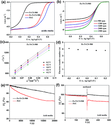
The ORR catalytic behaviour has also been investigated in acidic media. ORR activities of Fe–N–CS-700, 800, 900 and 1000 were shown in Fig. S7,† and Fe–N–CS-900 exhibited the best ORR activity with the most positive half-wave potential and the largest current density. Furthermore, Fig. 6a showed Fe–N–CS-900 had significantly high ORR activity and it half-wave potential was only 80 mV negative than that of Pt/C catalyst; besides, the limiting current density of Fe–N–CS-900 was comparable to that of commercial Pt/C catalyst. The corresponding K–L plots for Fe–N–CS-900 also exhibited the good linearity and the electron transfer number was calculated to be around 4 at different potential range, meaning that Fe–N–CS-900 also catalysed a 4e− oxygen reduction process in 0.5 M H2SO4 solution. The i/i0 in Fig. 6e were based on chronoamperometric responses (Fig. S8b†) for the ORR on Fe–N–CS-900 catalyst and commercial Pt/C catalyst modified electrodes. It was shown that Fe–N–CS-900 exhibited higher stability for ORR than commercial Pt/C catalyst, as revealed by relatively lower attenuation rate of current density than Pt/C catalyst. Fig. 6f suggested that Fe–N–CS-900 catalyst had also better methanol tolerance than Pt/C catalyst in acidic media. It is noted that the N–CS-900 catalyst exhibited much lower ORR activity than that of Fe–N–CS-900 (Fig. 6a), indicating again that the presence of iron played an important role to the N-doped carbon spheres for ORR in acidic media.
To confirm the significance of hierarchically mesoporous structure on the ORR performance of NPM catalysts, we compared the ORR performance of Fe–N–CS/SiO2-900 with Fe–N–CS-900 in both alkaline and acidic media. The electrocatalytic study (Fig. 7) showed that Fe–N–CS/SiO2-900 catalyst had the lower ORR activity than that of Fe–N–CS-900 in both alkaline and acidic media. These results indicated that well-developed hierarchically mesoporous structure with high surface area could facilitate the exposure of active sites and benefit the mass-transfer of the reactants and products, leading to higher catalytic activity.
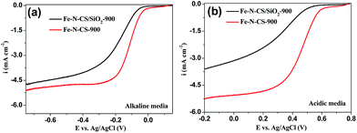 | ||
| Fig. 7 LSV curves of Fe–N–CS/SiO2-900 and Fe–N–CS-900 catalysts modified electrodes at rotation rate of 1600 rpm in O2-saturated (a) alkaline media and (b) acidic media, respectively. | ||
Conclusions
In this work, we fabricated Fe and N co-doping hierarchically mesoporous carbon spheres by nanocasting method. The obtained catalyst (Fe–N–CS-900) had high surface area (758 m2 g−1) and hierarchically mesoporous structure (2 nm, 25 nm). It is demonstrated that Fe–N–CS-900 exhibited high ORR performance in both alkaline and acidic media. We attributed highly efficient catalytic activity to the well-defined hierarchically mesoporous carbon structure with high surface area and homogeneous distribution of iron–nitrogen active sites. In addition, Fe–N–CS-900 also exhibited higher stability, better methanol tolerance and favoured efficient four electron transfer process in both alkaline and acidic media. The iron and nitrogen co-doped hierarchically mesoporous carbon spheres could have potential applications in PEMFCs and metal air batteries.Acknowledgements
This work was supported by NSFC (no. 21373116, 21421001 and 21534005), the Tianjin Natural Science Research Fund (13JCYBJC18300), RFDP (20120031110005), and the MOE Innovation Team (IRT13022) of China.Notes and references
- G. Wu and P. Zelenay, Acc. Chem. Res., 2013, 46, 1878 CrossRef CAS PubMed.
- F. Cheng and J. Chen, Chem. Soc. Rev., 2012, 41, 2172 RSC.
- J. Wu and H. Yang, Acc. Chem. Res., 2013, 46, 1848 CrossRef CAS PubMed.
- Y. Bing, H. Liu, L. Zhang, D. Ghosh and J. Zhang, Chem. Soc. Rev., 2010, 39, 2184 RSC.
- X. J. Sun, Y. W. Zhang, P. Song, J. Pan, L. Zhuang, W. L. Xu and W. Xing, ACS Catal., 2013, 3, 1726 CrossRef CAS.
- D.-S. Yang, D. Bhattacharjya, S. Inamdar, J. Park and J.-S. Yu, J. Am. Chem. Soc., 2012, 134, 16127 CrossRef CAS PubMed.
- Z. Yang, Z. Yao, G. Li, G. Fang, H. Nie, Z. Liu, X. Zhou, X. a. Chen and S. Huang, ACS Nano, 2011, 6, 205 CrossRef CAS PubMed.
- S. Yang, L. Zhi, K. Tang, X. Feng, J. Maier and K. Müllen, Adv. Funct. Mater., 2012, 22, 3634 CrossRef CAS.
- L. Yang, S. Jiang, Y. Zhao, L. Zhu, S. Chen, X. Wang, Q. Wu, J. Ma, Y. Ma and Z. Hu, Angew. Chem., Int. Ed., 2011, 50, 7132 CrossRef CAS PubMed.
- Z. Yao, H. Nie, Z. Yang, X. Zhou, Z. Liu and S. Huang, Chem. Commun., 2012, 48, 1027 RSC.
- N. Daems, X. Sheng, I. Vankelecom and P. Pescarmona, J. Mater. Chem. A, 2014, 2, 4085 CAS.
- M. Wu, J. Qiao, Y. Liu, J. Zhang, X. J. Zhou and K. X. Li, Green Chem., 2016, 18, 2699 RSC.
- Z. Wu, R. Liu, J. Wang, J. Zhu, W. P. Xiao, C. J. Xuan, W. Lei and D. L. Wang, Nanoscale, 2016, 8, 19086 RSC.
- X. Chen, X. Chen, X. Xu, Z. Yang, Z. Liu, L. Zhang, X. Xu, Y. Chen and S. Huang, Nanoscale, 2014, 6, 13740 RSC.
- K. Ding, Q. Liu, Y. Bu, Y. Huang, J. Lv, J. Wu, S. C. Abbas and Y. Wang, RSC Adv., 2016, 6, 93318 RSC.
- Y.-L. Liu, C.-X. Shi, X.-Y. Xu, P.-C. Sun and T.-H. Chen, J. Power Sources, 2015, 283, 389 CrossRef CAS.
- K. P. Gong, F. Du, Z. H. Xia, M. Durstock and L. M. Dai, Science, 2009, 323, 760 CrossRef CAS PubMed.
- L. Qu, Y. Liu, J.-B. Baek and L. Dai, ACS Nano, 2010, 4, 1321 CrossRef CAS PubMed.
- R. Liu, D. Wu, X. Feng and K. Müllen, Angew. Chem., Int. Ed., 2010, 49, 2565 CrossRef CAS PubMed.
- T. Y. Ma, Y. Zheng, S. Dai, M. Jaroniec and S. Z. Qiao, J. Mater. Chem. A, 2014, 2, 8676 CAS.
- Y. Liang, H. Wang, J. Zhou, Y. Li, J. Wang, T. Regier and H. Dai, J. Am. Chem. Soc., 2012, 134, 3517 CrossRef CAS PubMed.
- S. Guo, S. Zhang, L. Wu and S. Sun, Angew. Chem., Int. Ed., 2012, 51, 11770 CrossRef CAS PubMed.
- Y. Liang, H. Wang, P. Diao, W. Chang, G. Hong, Y. Li, M. Gong, L. Xie, J. Zhou, J. Wang, T. Z. Regier, F. Wei and H. Dai, J. Am. Chem. Soc., 2012, 134, 15849 CrossRef CAS PubMed.
- Y. Liang, Y. Li, H. Wang, J. Zhou, J. Wang, T. Regier and H. Dai, Nat. Mater., 2011, 10, 780 CrossRef CAS PubMed.
- N. Daems, X. Sheng, I. F. J. Vankelecom and P. P. Pescarmona, J. Mater. Chem. A, 2014, 2, 4085 CAS.
- G. Liu, X. Li, P. Ganesan and B. N. Popov, Electrochim. Acta, 2010, 55, 2853 CrossRef CAS.
- M. Lefèvre, E. Proietti, F. Jaouen and J.-P. Dodelet, Science, 2009, 324, 71 CrossRef PubMed.
- Y. Zhao, K. Watanabe and K. Hashimoto, J. Am. Chem. Soc., 2012, 134, 19528 CrossRef CAS PubMed.
- L. Lin, Q. Zhu and A.-W. Xu, J. Am. Chem. Soc., 2014, 136, 11027 CrossRef CAS PubMed.
- W. Niu, L. Li, X. Liu, N. Wang, J. Liu, W. Zhou, Z. Tang and S. Chen, J. Am. Chem. Soc., 2015, 137, 5555 CrossRef CAS PubMed.
- M. Li, X. Bo, Y. Zhang, C. Han, N. Anaclet and L. Guo, J. Mater. Chem. A, 2014, 2, 11672 CAS.
- F. Jaouen, E. Proietti, M. Lefevre, R. Chenitz, J.-P. Dodelet, G. Wu, H. T. Chung, C. M. Johnston and P. Zelenay, Energy Environ. Sci., 2011, 4, 114 CAS.
- J. C. Li, S. Y. Zhao, P. X. Hou, R. P. Fang, C. Liu, J. Liang, J. Luan, X. Y. Shan and H. M. Cheng, Nanoscale, 2015, 7, 19201 RSC.
- H.-W. Liang, W. Wei, Z.-S. Wu, X. Feng and K. Müllen, J. Am. Chem. Soc., 2013, 135, 16002 CrossRef CAS PubMed.
- A. Kong, B. Dong, X. Zhu, Y. Kong, J. Zhang and Y. Shan, Chem.–Eur. J., 2013, 19, 16170 CrossRef CAS PubMed.
- J. Y. Cheon, T. Kim, Y. Choi, H. Y. Jeong, M. G. Kim, Y. J. Sa, J. Kim, Z. Lee, T.-H. Yang, K. Kwon, O. Terasaki, G.-G. Park, R. R. Adzic and S. H. Joo, Sci. Rep., 2013, 3, 2715 Search PubMed.
- A. Kong, Y. Kong, X. Zhu, Z. Han and Y. Shan, Carbon, 2014, 78, 49 CrossRef CAS.
- A. Kong, X. Zhu, Z. Han, Y. Yu, Y. Zhang, B. Dong and Y. Shan, ACS Catal., 2014, 4, 1793 CrossRef CAS.
- C. Deng, H. Zhong, L. Yao, S. Liu, Z. Xu and H. Zhang, ChemSusChem, 2014, 7, 3435 CrossRef CAS PubMed.
- Y. Liu, X.-J. Jin, A.-X. Tuo and H. Liu, RSC Adv., 2016, 6, 105211 RSC.
- J.-G. Wang, H.-J. Zhou, P.-C. Sun, D.-T. Ding and T.-H. Chen, Chem. Mater., 2010, 22, 3829 CrossRef CAS.
- S. Chen, J. Bi, Y. Zhao, L. Yang, C. Zhang, Y. Ma, Q. Wu, X. Wang and Z. Hu, Adv. Mater., 2012, 24, 5593 CrossRef CAS PubMed.
- R. Arrigo, M. Hävecker, R. Schlögl and D. S. Su, Chem. Commun., 2008, 4891 RSC.
- W. Yang, T.-P. Fellinger and M. Antonietti, J. Am. Chem. Soc., 2010, 133, 206 CrossRef PubMed.
- J. Liang, Y. Zheng, J. Chen, J. Liu, D. Hulicova-Jurcakova, M. Jaroniec and S. Z. Qiao, Angew. Chem., Int. Ed., 2012, 51, 3892 CrossRef CAS PubMed.
- X. J. Sun, P. Song, Y. W. Zhang, C. P. Liu, W. L. Xu and W. Xing, Sci. Rep., 2013, 3, 2505 Search PubMed.
- S. Zhang, B. Liu and S. Chen, Phys. Chem. Chem. Phys., 2013, 15, 18482 RSC.
- R. Silva, D. Voiry, M. Chhowalla and T. Asefa, J. Am. Chem. Soc., 2013, 135, 7823 CrossRef CAS PubMed.
- R. Wang, T. Zhou, H. Wang, H. Feng and S. Ji, J. Power Sources, 2014, 269, 54 CrossRef CAS.
- S. Kundu, T. C. Nagaiah, W. Xia, Y. Wang, S. V. Dommele, J. H. Bitter, M. Santa, G. Grundmeier, M. Bron, W. Schuhmann and M. Muhler, J. Phys. Chem. C, 2009, 113, 14302 CAS.
Footnotes |
| † Electronic supplementary information (ESI) available. See DOI: 10.1039/c6ra26917f |
| ‡ Contributed equally in this work. |
| This journal is © The Royal Society of Chemistry 2017 |


