 Open Access Article
Measurement of Wenzel roughness factor by laser scanning confocal microscopy
Ai Hongru a,
Li Xiangqina,
Shi Shuyanb,
Zhang Yinga and
Liu Tianqing*a
aSchool of Chemical Engineering, Dalian University of Technology, Dalian 116024, Liaoning, China. E-mail: liutq@dlut.edu.cn; Tel: +86-411-84706360
bSchool of Materials Science and Engineering, Dalian University of Technology, Dalian 116024, Liaoning, China
First published on 20th January 2017
Abstract
The Wenzel roughness factor r is one of the most important parameters to characterize a super-hydrophobic surface. In this study, in order to prove the feasibility of using laser scanning confocal microscopy (LSCM) to measure the roughness factor r, the detected r values by LSCM on texture-regular surfaces were compared with those calculated firstly, and then the r values measured by LSCM for texture-irregular rough surfaces were compared with those measured by AFM. The results show that the r values of texture-regular surfaces measured by LSCM are close to those calculated, and the LSCM measured r values of texture-irregular surfaces with small roughness are consistent with those measured by AFM. Moreover, the r values of texture-irregular surfaces with large roughness can only be measured by LSCM, the detected r values of three such super-hydrophobic surfaces are 2.13 ± 0.01, 2.12 ± 0.01 and 2.13 ± 0.02, respectively. In addition, it is proved that the r measured by LSCM as a line length ratio is equal to the original definition of roughness factor as the ratio of actual area of solid surface to the horizontal projected area. Consequently, it is reliable to measure the r value of a texture-irregular surface with large roughness in micro or submicro scale by LSCM.
1. Introduction
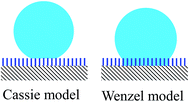
There are two classical wetting theories to describe droplets on rough surfaces: the Wenzel model and the Cassie–Baxter model as shown in Fig. 1, where the Wenzel model is expressed as:1
cos![[thin space (1/6-em)]](https://www.rsc.org/images/entities/char_2009.gif) θw = r θw = r![[thin space (1/6-em)]](https://www.rsc.org/images/entities/char_2009.gif) cos cos![[thin space (1/6-em)]](https://www.rsc.org/images/entities/char_2009.gif) θ0 θ0
| (1) |
The condensation research on super-hydrophobic surface has important value in practical applications, such as anti-frosting in air conditioning and refrigeration, and self-cleaning of car windshield.3–12 In these cases, condensate drops are expected to be spherical and depart from the material surface as soon as possible. However, Chen and his partners13 found that the condensate drops presented either a Cassie state14 or a mixed Wenzel–Cassie state15 only on a surface with proper roughness factors. Enright and his coworkers16 proved that the possible wetting state of condensate drops under nonequilibrium conditions was determined by energy and roughness factor r. Enright et al.,16 Liu et al.,17 and Rykaczewski et al.18–20 reported that only on the nano-structured surfaces with proper roughness factors, the small condensate drops could grow to the final partially wetted droplets. Shirtcliffe et al.21 showed that both contact angle and contact angle hysteresis on rough surfaces were obviously influenced by roughness factor. It can be concluded that roughness factor r plays an important role for the drops in their super-hydrophobic behavior, and the determination of it is valuable for the research on the super-hydrophobic surface.
The r value of a surface with regular microstructure can be calculated by corresponding formulas directly;22 while that of a surface with irregular microstructure can't be found by calculation. For the latter, two assay methods are usually employed to obtain the r value. One is to calculate r by eqn (1) after the apparent contact angle θw is measured. However, the equilibrium Wenzel state of a droplet is difficult to realize because it's not easy for a sessile drop to immerse its underneath microstructure completely and just in equilibrium state at the same time. Therefore, large errors occur with this method. The other scheme is to measure r value by atomic force microscope (AFM). However, it is hard for the AFM probe to penetrate into the microstructure deeply and consequently, it is only applicable to the surface with small roughness. For example, Qu et al.23 and Khedir et al.24 measured the super-hydrophobic surfaces with low r values of 1.42 and 1.7, respectively. But it is difficult for AFM to measure the r values of surfaces with large roughness correctly.
Laser scanning confocal microscopy (LSCM) scans sample surfaces with laser and forms a photography with high-contrast and high-resolution. When a surface is scanned by LSCM, there is no restriction on roughness and any surfaces with different r values may be detected by LSCM without damage to the sample or to the machine.25 Currently, LSCM is mainly applied to the biological field, such as observing cell apoptosis and analyzing DNA and RNA quantitatively, and it has not yet been reported in literatures that the roughness factors of super-hydrophobic surfaces are determined by LSCM.
Therefore in this work, we tried to apply LSCM to measure the r values of different rough surfaces. The reliability of measuring the r values by LSCM was proved by the companied AFM measurement for low rough surfaces since the assay results by LSCM and AFM were consistent. But for the surfaces with large roughness only LSCM could be used to measure the high r values while AFM is limited in this case because the AFM probe is difficult to penetrate into the microstructure deeply.
2. Materials and methods
2.1 Materials and instruments
Aluminum foil (purity > 99%, 2 mm in thickness), and (heptadecafluoro-1,1,2,2-tetradecyl)trimethoxysilane (analytical pure) were purchased from Dalian aluminum factory (China) and Alfa Aesar (USA), respectively. Hydrofluoric acid (HF), hydrochloric acid (HCl), methanol, acetone and ammonia were all analytical pure (Aladdin Reagent Co.).A scanning electron microscope (SEM, NOVA NANOSEM 450, FEI, USA), a LSCM (Olympus OLS4000, Japan) with 405 nm wavelength of semiconductor laser applied, and an AFM (Picoscan 2500, Agilent Technologies, USA) were used in the experiments. The probe of AFM is a rotated monolithic silicon one, with symmetric tip shape, tip height 17 μm, and tip set back 15 μm. And the tapping mode was utilized in the AFM experiments.
2.2 Surface preparation and characterization
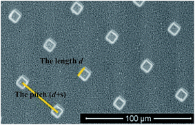
r value of a texture-regular surface can be calculated directly through the following formula:
 | (2) |
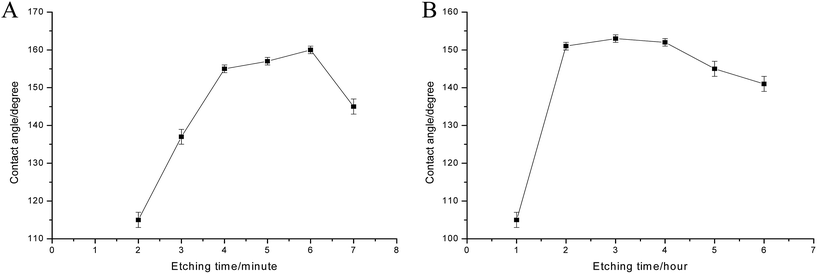 | ||
| Fig. 2 The relation between etching time and contact angle ((A) surface etched by acid; (B) surface etched by alkaline). | ||
Moreover, the contact angle hysteresis of above mentioned six surfaces were measured with a contact angle meter (OCAH200, Dataphysics, Germany). The hysteresis of all these surfaces is smaller than 5°, as shown in Table 1.
| Surfaces | Sa1 | Sa2 | Sa3 | Sb1 | Sb2 | Sb3 |
|---|---|---|---|---|---|---|
| Contact angle hysteresis, ° | 2.0 | 1.8 | 1.5 | 4.5 | 3.5 | 3.8 |
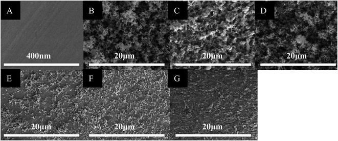
The microstructures of the above prepared texture-irregular surfaces were observed by SEM firstly. According to the SEM graphs, the surfaces with smaller roughness were selected to measure the r values by LSCM and AFM, respectively, and the surfaces with relatively larger roughness were selected to measure the r values by LSCM.
2.3 Roughness factor measurement by LSCM
LSCM images any point in space and then 2D or 3D images of a sample are formed through computer scanning.28In our experiments, after a measured surface was placed on the sample table, the laser was pointed to a spot on the surface far away from the edges of the sample firstly. Then the laser started to scan along a straight line from the spot as the origin. After a certain length was scanned the laser returned to the origin and the sample table was rotated clockwise for 12°. Then the second straight line scanning was performed. In this way, totally thirty lines were scanned from the same origin. Then the laser was moved to another origin and the scans were repeated. Totally three origins were selected and ninety straight lines were scanned. On a texture-regular surface the scanned length of each line was 2500 μm, while on a texture-irregular surface the length was 2300 μm. Additionally, the rough heights of measured surfaces, z coordinate values, were recorded every 0.125 μm along each scanned straight line. If xi and zi mean the x and z values at a measured point i along a scanned line, the line length ratio of actual laser scanned surface curve to the projected straight line for each scanned line can be calculated by:
 | (3) |
![[thin space (1/6-em)]](https://www.rsc.org/images/entities/char_2009.gif) 001 and 18
001 and 18![[thin space (1/6-em)]](https://www.rsc.org/images/entities/char_2009.gif) 401 respectively for texture-regular and irregular surfaces.
401 respectively for texture-regular and irregular surfaces.
Finally the line length ratio of a measured surface can be obtained by the average of all rj values of 90 scanned lines, i.e.:
 | (4) |
And the line length ratio will be proved to be the same as the area ratio of a rough surface in the later part of this study.
2.4 Roughness factor measurement by AFM
AFM can record the undulating movement of the cantilever by interaction force between the surface and the probe on the cantilever. Thus, the x, y, z of each scanned point and the final 3D morphology of the surface are obtained.29 In this experiment, the area D of 10 μm × 10 μm on a surface was selected and scanned by the probe of AFM. Then rn can be calculated by the formula below based on the recorded x, y and z values:
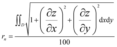 | (5) |
The tests on each surface were repeated in three different regions. Finally, roughness factor r of a measured surface can be obtained by:
 | (6) |
2.5 Statistical analysis
The tests on each surface were repeated three times (n = 3), and the results were expressed as the mean value of the data ± standard error. Significant levels were determined using the one-way analysis of variance and expressed with P < 0.05.3. Results and discussion
3.1 Morphology of rough surfaces
3.2 Roughness factors measurement by LSCM
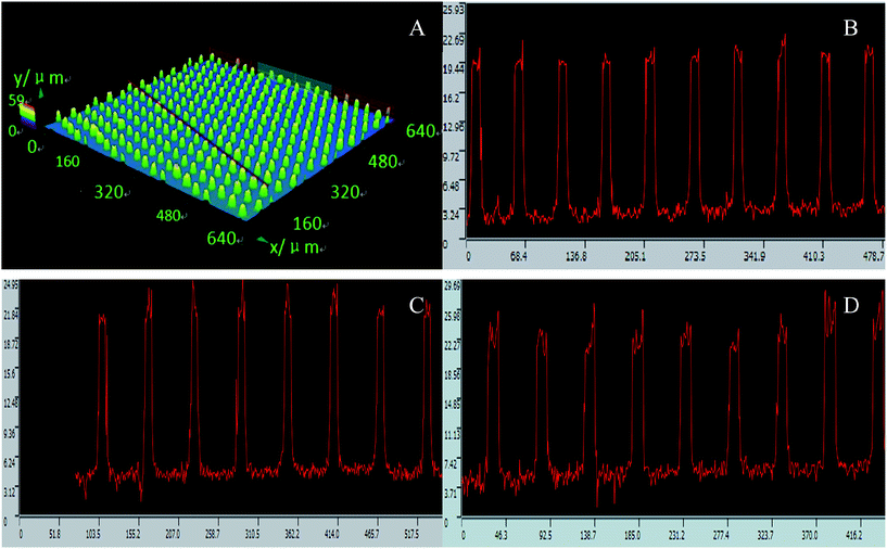 | ||
| Fig. 5 LSCM images of three texture-regular surfaces. (A) The scan path on Sr1; (B), (C) and (D) the scanned pillar profiles of Sr1, Sr2 and Sr3 respectively. | ||
Then the r values of texture-regular surfaces Sr1, Sr2 and Sr3 measured by LSCM as well as those calculated by eqn (2) are compared, as shown in Table 2. It can be seen that the r values from the two different methods are close to each other. In fact, the statistical analysis of the data shows that there is no significant difference between them in the three groups at P < 0.05, implying the feasibility of measuring r by LSCM for a texture-regular surface.
| Surface | r (by calculation) | r (by LSCM) |
|---|---|---|
| Sr1 | 1.53 | 1.56 ± 0.02 |
| Sr2 | 1.33 | 1.35 ± 0.01 |
| Sr3 | 1.19 | 1.17 ± 0.01 |
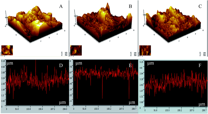 | ||
| Fig. 6 AFM and LSCM images of texture-irregular surfaces, Sb1 (A and D), Sb2 (B and E) and Sb3 (C and F). | ||
The relatively smaller r values of the surfaces were measured by both LSCM and AFM, and the results are shown in Table 3. The statistical analysis shows that there is no significant difference between the data in the two groups at P < 0.05, implying the feasibility of measuring r value by LSCM for a texture-irregular surface.
| Surface | r (by AFM) | r (by LSCM) |
|---|---|---|
| Sb1 | 1.25 ± 0.02 | 1.26 ± 0.02 |
| Sb2 | 1.26 ± 0.01 | 1.25 ± 0.01 |
| Sb3 | 1.25 ± 0.01 | 1.27 ± 0.02 |
| Sa1 | — | 2.13 ± 0.01 |
| Sa1 | — | 2.12 ± 0.01 |
| Sa1 | — | 2.13 ± 0.02 |
The above results illustrate that the r values measured by LSCM are close to those determined by the other methods whether the surfaces are regular or not. Therefore, it is reliable to detect r values of micro super-hydrophobic surfaces by LSCM. Three texture-irregular surfaces with relatively large roughness etched by acid were thus used as examples for their r values detection by LSCM. And the scanned images are shown in Fig. 7. It is clear that the microstructure scale of the surfaces is large and the roughness average size is more than 3 μm. Meanwhile the measured r values are also shown in Table 3. It can be seen that the r values of these surfaces are indeed obviously greater than those of alkaline-etched surfaces. In addition, the AFM was also tried but limited to scan these surfaces since it is hard for the AFM probe to penetrate into the microstructure of these surfaces deeply.
Great r values are usually required for rough surfaces to sustain their super-hydrophobicity,13,27 and the determination of the roughness factor is essential for the research on a super-hydrophobic surface. However, the reliable measurement methods of large r values for texture-irregular surfaces are limited to date. The LSCM was used for the first time in this study to measure the r values of super-hydrophobic surfaces, and it has been proved that the LSCM is able to detect rough surfaces with large r values.
3.3 Proof of line length ratio equal to area ratio
The r measured here by LSCM is the line length ratio (LLR) of a solid–gas interface curve to the horizontal projected line, while the original definition of roughness factor r is the ratio of actual area of solid surface to the horizontal projected area, namely the area ratio (AR). It is thus necessary to prove that the LLR is equal to the AR. The following is the proof.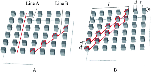 | ||
| Fig. 8 Schematic diagram of the rough structure parameters and different gas–solid interface lines on a texture-regular surface. | ||
The respective LLR of any two lines on the surface may be different due to the diverse positions of the lines. As an example shown in Fig. 8A, the LLR of line A is 1 while that of line B is greater than 1. Therefore, it is necessary to apply statistics to find the mathematical expectation of LLR for texture-regular surfaces. In another word, the demanded LLR should be the averaged LLR of all the lines on the surface.
If a solid–gas interface line at any position with length l in horizontal direction is moved up for a distance of (d + s) in vertical direction, as shown in Fig. 8B, the line-passed projection region is that of a parallelogram with base of (d + s) and height of l, i.e. the area of l(d + s), and the number of the pillars in the region is l/(d + s).
Now suppose the above solid–gas interface line has a width of w (w is sufficiently small) in vertical direction, then the projected area of the line is wl. Next consider the line-passed projection region mentioned above is fully covered by a lot of such solid–gas interface lines. Thus there will be (d + s)/w lines in the region. If Ai represents the solid–gas interface area of each line, then  means all solid–gas interface area in the region, i.e.:
 | (7) |
Furthermore, let ri represents the AR of each line (ri also means the LLR of each line if w is sufficiently small):
 | (8) |
Then  is the summarization of all ri in the region:
 | (9) |
Finally, if  is divided by the number of all the lines in the region, the averaged LLR can be found:
 | (10) |
It is thus clear that the averaged LLR of a texture-regular surface is equal to the AR.
 | (11) |
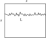 | ||
| Fig. 9 Schematic of actual solid–gas interface line length and the projection length on a texture-irregular surface. | ||
In a word, for a surface whether the rough structure is regular or not, the AR is equal to the LLR. Thus, it is feasible and reliable to measure r value of a texture-irregular surface by LSCM.
3.4 Validity of roughness factor measurement by LSCM
In our LSCM measurements, either for a regular or for an irregular surface, 30 radial lines were scanned from a same origin on the surface by rotating the sample table every 12°. Totally 3 such original points were randomly selected so that 90 radial lines were scanned. In this way, the r value, the Wenzel roughness factor, can be averaged along different directions and at different locations on a surface. Moreover, the length of each scanned radial line is 2.3–2.5 mm, which is far greater than the micro scaled structures on a regular or irregular rough surface. Therefore, the measured r values have statistical significance. We also think that this protocol is valid for any shaped rough surfaces as long as the scanned radial lines are enough. Thus we think the regular pillar shape does not influence the measurement although we only used one type of regular pillar structures.The relation between light wavelength and the distinguishable distance is σ = 0.61λ/NA, where σ is the minimum distinguishable distance, λ is the wavelength and NA means numerical aperture. NA is 1.25–1.30 when the multiple of objective lens is 90× to 100×. Since the wavelength of the LSCM we used is 405 nm its resolution to scan a rough surface will be about 200 nm. Therefore, the measurement of Wenzel roughness factors by LSCM is valid only for the rough surfaces with micro or submicro sized textures, but not nano scaled structures.
4. Conclusions
It is feasible and reliable to measure the r values of surfaces with micro or submicro rough structures by LSCM. This method may be applicable more widely than AFM method because scan probe is not used by LSCM, so that any concerns about the damage of probe no longer exist, especially for the detection of a texture-irregular surface with large roughness.Acknowledgements
The authors would like to acknowledge the financial support from the National Science Foundation (NSF) of China (21676041).References
- R. N. Wenzel, J. Phys. Chem., 1949, 53(9), 1466 CrossRef CAS.
- Q. P. Ke, G. L. Li, T. G. Hao, T. He and X. M. Li, Prog. Chem., 2010, 22(2/3), 284 CAS.
- N. Miljkovic, R. Enright, Y. Nam, K. Lopez, N. Dou, J. Sack and E. N. Wang, Nano Lett., 2013, 13(1), 179 CrossRef CAS PubMed.
- K. Rykaczewski, A. T. Paxson, S. Anand, X. Chen, Z. Wang and K. K. Varanasi, Langmuir, 2013, 29(3), 881 CrossRef CAS PubMed.
- A. Nakajima, K. Hashimoto and T. Watanabe, Monatsh. Chem., 2001, 132, 31 CrossRef CAS.
- G. Grevoisier, P. Fabre, J. M. Corpart and L. Leibler, Science, 1999, 285(5432), 1246 CrossRef.
- K. R. Shull and T. E. Karis, Langmuir, 1994, 10(1), 334 CrossRef CAS.
- F. Rieutord and M. Salmeron, J. Phys. Chem. B, 1998, 102(20), 3941 CrossRef CAS.
- O. N. Tretirnikov and Y. Ikada, Macromolecules, 1997, 30(4), 1086 CrossRef.
- D. Yoo, S. S. Shiratori and M. F. Rubner, Macromolecules, 1998, 31(13), 4309 CrossRef CAS.
- A. F. Thunemann, U. Schnoller, O. Nayken and B. Voit, Macromolecules, 2000, 33(15), 5665 CrossRef.
- A. F. Thunemann, Langmuir, 2000, 16(2), 824–828 CrossRef.
- C. H. Chen, Q. Cai and C. Tsai, Appl. Phys. Lett., 2007, 90(17), 173108 CrossRef.
- C. Dietz and K. Rykaczewski, Appl. Phys. Lett., 2010, 97(3), 033104 CrossRef.
- N. Miljkovic, R. Enright and E. N. Wang, ACS Nano, 2012, 6(2), 1776 CrossRef CAS PubMed.
- R. Enright, N. Miljkovic and A. Obeidi, Langmuir, 2012, 28(40), 14424 CrossRef CAS PubMed.
- T. Q. Liu, W. Sun, X. Q. Li, X. Y. Sun and H. R. Ai, Acta Phys.-Chim. Sin., 2013, 29(8), 1762 CAS.
- K. Rykaczewski, W. A. Osborn, J. Chinn, M. L. Walker, J. H. J. Scott, W. Jones, C. L. Hao, S. H. Yao and Z. K. Wang, Soft Matter, 2012, 8, 8786 RSC.
- K. Rykaczewski, Langmuir, 2012, 28, 7720 CrossRef CAS PubMed.
- K. Rykaczewski and J. H. J. Scott, ACS Nano, 2011, 5(7), 5962 CrossRef CAS PubMed.
- N. J. Shirtcliffe, G. McHale and M. I. Newton, Langmuir, 2005, 21(3), 937 CrossRef CAS PubMed.
- M. Nosonovsky and B. Bhushan, Ultramicroscopy, 2007, 107(10), 969 CrossRef CAS PubMed.
- A. L. Qu, X. F. Wen and P. H. Pi, Acta Polym. Sin., 2007, 12, 1176 Search PubMed.
- K. R. Khedir, G. K. Kannarpady and H. Ishihara, Langmuir, 2011, 27(8), 4661 CrossRef CAS PubMed.
- J. Wang, Y. Wang, J. Gong and W. Tang, Modern Instrument, 2009, 15(4), 50 Search PubMed.
- X. Chen, J. Wu, R. Ma, M. Hua, N. Koratkar, S. Yao and Z. Wang, Adv. Funct. Mater., 2011, 21(24), 4617 CrossRef CAS.
- Y. F. Li, Z. J. Yu, Y. F. Yu, S. B. Huo and S. P. Song, J. Chem. Eng. Chin. Univ., 2008, 22(1), 6 CrossRef.
- J. T. Han, Y. Z. Ma and Z. J. Wang, Quality Control & Safety, 2008, 29(5), 104 Search PubMed.
- T. Junno, S. B. Carlson, H. Q. Xu, L. Montelius and L. Samuelson, Appl. Phys. Lett., 1998, 72(5), 548 CrossRef CAS.
| This journal is © The Royal Society of Chemistry 2017 |

