
 Open Access Article
 This Open Access Article is licensed under a
 Creative Commons Attribution 3.0 Unported Licence
Beyond pristine MOFs: carbon dioxide capture by metal–organic frameworks (MOFs)-derived porous carbon materials†
Hye Ryeon Kima,
Tae-Ung Yoonc,
Seung-Ik Kimc,
Jihyun An*b,
Youn-Sang Bae*c and
Chang Yeon Lee *ad
*ad
aEnergy and Chemical Engineering, Incheon National University, 119, Academy-ro, Yeonsu-gu, Incheon, 22012, Republic of Korea. E-mail: cylee@inu.ac.kr
bDepartment of Chemistry Education, Seoul National University, 1 Gwanak-ro, Gwanak-gu, Seoul, 08826, Republic of Korea. E-mail: jihyunan@snu.ac.kr
cDepartment of Chemical and Biomolecular Engineering, Yonsei University, 50 Yonsei-ro, Seodaemun-gu, Seoul, 03722, Republic of Korea. E-mail: mowbae@yonsei.ac.kr
dInnovation Center for Chemical Engineering, Incheon National University, 119, Academy-ro, Yeonsu-gu, Incheon, 22012, Republic of Korea
First published on 5th January 2017
Abstract
Porous carbon materials were synthesized by simple pyrolysis of various zinc-containing MOFs. These materials exhibited superior CO2 capacities compared to those of the pristine MOFs. Moreover, the porous carbon materials, in contrast to their parent MOFs, showed an excellent CO2 separation ability under humid conditions.
Continuous carbon dioxide (CO2) emission from anthropogenic sources causes severe environmental issues such as global warming. The largest CO2-emitting industrial sources are coal-fired power plants, in which post-combustion capture is often utilized to remove CO2 from exhaust gas generated from combustion of fossil fuels. Flue gas from power plants is composed of carbon dioxide (∼15–16%), water vapor (∼5–7%) and nitrogen (∼70–75%) at ∼1 bar.1 In order to separate and capture CO2 from power plant flue gas emissions, monoethanol amine (MEA)-based aqueous solution is conventionally employed. However, this wet-process requires a high-energy cost to regenerate absorbents because of not only an inherent high heat capacity of water in MEA solution but also chemisorption of CO2 on MEA. Approximately 30% of energy produced from the power plants is usually wasted to regenerate the aqueous MEA solution. Moreover, volatility of MEA solution at high temperature and its corrosive character limit a wide use of MEA as an adsorbent for large-scale CO2 capture. Porous solid materials, which have lower heat capacity, have been emerging as a potential adsorbent for CO2 capture applications. Materials including zeolites,2 carbon materials,3 porous organic polymers (POPs),4 amine-grafted silicas5,6 and so on have been investigated so far.
Among the various porous solids, metal–organic frameworks (MOFs), which are assembled by a coordination bond between a rigid organic ligand and diverse metal ions or metal clusters, have emerged as an outstanding adsorbent for CO2 capture because of their enormous surface area and finely tunable surface functionality. The work from Matzger and coworkers has demonstrated MOFs' excellent promising potential as CO2 adsorbent, showing that [Mg2 (DOBDC)] (DOBDC = 2,5-dioxido-1,4-benzenedicarboxylate) exhibited a remarkable CO2 uptake capacity (27.5 wt%) at 298 K and 1 bar.7 However, most MOFs show instability toward moisture unfortunately, and it is one of the greatest challenges for establishing CO2 capture from the flue gas containing water vapor. Particularly, MOF-5 and MOF-177, composed of oxo-zinc secondary building unit and carboxylate linker, are known for their extreme instability upon exposure to moisture.8 In fact, MOF-5 showed a significant decrease of dynamic CO2 adsorption capacity under humid condition (RH = 65%) during three consecutive cycles.9
Porous carbon materials and metal or metal oxide–carbon (M@C or MO@C) composites which are derived from MOFs have been used widely as platforms for green energy applications such as fuel cells, Li-ion batteries, supercapacitors and solar cells.10 In general, simple pyrolysis of pristine MOF precursors affords these materials, and MOF-derived porous carbon materials are moisture stable due to the inherent hydrophobic property of porous carbon. While numerous examples exist for electrochemical applications with these materials, to the best our knowledge, there are relatively few examples were reported for capturing CO2 with MOF-derived porous carbon materials,11–16 and most of the works are limited to ZIF-8 (ZIF: zeolitic imidazolate frameworks) which is constructed from imidazolates and zinc(II) ions. Besides, CO2 adsorption study of these materials under humid conditions has not been reported yet.
Herein we report a simple method for preparing porous carbon materials derived from zinc-containing MOFs (MOF-5, MOF-177, and bioMOF-100) and their CO2 uptake properties. In addition, dynamic breakthrough experiments for these materials under humid conditions are also represented. We believe that these three MOFs can be suitable precursors for porous carbon materials because they have high surface areas over 3000 m2 g−1 and thermally removable zinc elements. Furthermore, bioMOF-100 contains nitrogens in adeninate ligands, thus CO2 capture performance of nitrogen-doped porous carbon material can be tested as well in this work (Scheme 1).
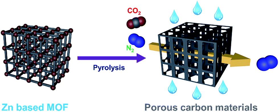 | ||
| Scheme 1 Schematic illustration of the preparation of porous carbon materials and their selective adsorption of CO2. | ||
MOF-5, MOF-177, and bioMOF-100 were synthesized by reported methods.17,18 In order to obtain porous carbon materials, zinc-based MOFs were pyrolyzed at 1000 °C for 6 h under Ar atmosphere. During the pyrolysis step, low boiling zinc metal (b.p. 907 °C) was completely removed and metal-free carbon materials were afforded consequently. Hereafter resultant porous carbons were denoted as M5-1000, M177-1000, and B100-1000, respectively.
The phase structures of porous carbons were studied via powder X-ray diffraction (PXRD) measurements (Fig. 1a). As shown in Fig. 1a, the samples displayed two weak and broad peaks around at 23 and 44°, which were assigned to the carbon (002) and (100) or (101) plane, respectively. These results indicate that the carbonized MOFs have an amorphous nature. Complete removal of zinc metal was verified by observing the absence of other peaks in PXRD.
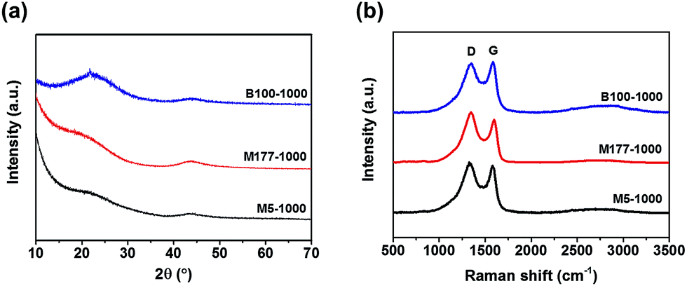 | ||
| Fig. 1 (a) Powder X-ray diffraction (PXRD) patterns of the porous carbons. (b) Raman spectra of M5-1000, M177-1000, and B100-1000. | ||
Local structure information of carbon was investigated by Raman spectroscopy (Fig. 1b). The pyrolyzed MOFs showed two distinct D and G bands centered at 1344 and 1587 cm−1 respectively, resulting from the disordered carbon structures and the vibration mode for the movement of two carbon atoms in a single graphene sheet in the opposite direction. The intensity ratio of G band to D band (IG/ID) is related to a degree of graphitization in carbon materials. The IG/ID values were 0.96, 0.87, and 1.03 for M5-1000, M177-1000, and B100-1000, respectively, indicating that the local carbon structures consist of both graphene and disordered carbon. Almost featureless second-order bands (2D and G + D) were observed between 2700 and 3000 cm−1 for all of the samples, suggesting a disordered carbon network as evidenced by the PXRD patterns.
Scanning electron microscopy (SEM) images of the porous carbons are shown in Fig. S3.† Interestingly, each morphology of the parent MOFs was found to be retained, even after heating at high temperature. This indicates that the carbon content of the MOFs is suitable for the formation of carbon materials and the MOF is a stable support for the synthesis of porous carbon materials.
Detailed information about pore structures and surface areas of the pyrolyzed carbon materials was investigated by N2 adsorption–desorption isotherms at 77 K. As shown in Fig. 2a, the isotherms of M5-1000 and M177-1000 revealed type IV shape with noticeable hysteresis, whereas that of B100-1000 exhibited type I shape with insignificant hysteresis. BET surface areas from the N2 isotherms are shown in Table 1. Surface areas of the porous carbons are linearly increased with increasing Zn contents of parent MOFs precursors (Table 1, Fig. S7†). Higher Zn contents in MOF precursors leads to a formation of larger amounts of Zn nanoparticles in the carbon matrix during the pyrolysis step. Given that an evaporation of these Zn nanoparticles from the carbon matrix is responsible for the formation of the porous carbon structures, the above linear relationship between Zn contents and surface area might result from the different ratio of Zn/C in the parent MOF. These results are well consistent with the previous work, which was done by Kim and coworkers.19 The DFT pore size distributions shown in Fig. S8† suggest that B100-1000 is micropore-dominant while M5-1000 and M177-1000 have significant amounts of mesopores as well as micropores.
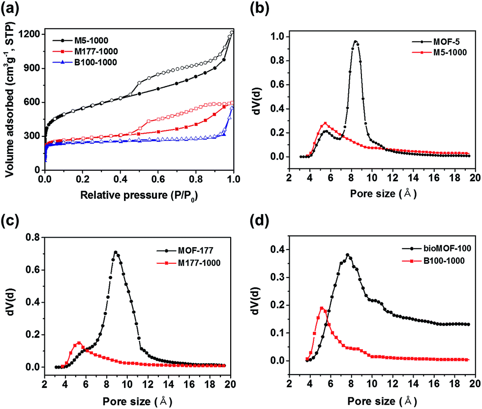 | ||
| Fig. 2 (a) N2 adsorption–desorption isotherms of the porous carbon materials. (b)–(d) H–K pore-size distributions of M5-1000, M177-1000, B100-1000 and their pristine counterparts, respectively. | ||
| Sample | Zn/C ratio of parent MOFs | BET surface area (m2 g−1) | CO2 uptake at 298 K (mmol g−1) | Qst CO2 (kJ mol−1) | Selectivity (IAST) | |||
|---|---|---|---|---|---|---|---|---|
| Parent MOFs | After pyrolysis | Parent MOFs (1 bar) | After pyrolysis | |||||
| 0.15 bar | 1 bar | |||||||
| a This value is obtained from ref. 18. | ||||||||
| M5-1000 | 0.167 | 3031 | 1978 | 1.09 | 0.81 | 3.13 | 28.1–22.1 | 21.6–11.0 |
| M177-1000 | 0.074 | 3337 | 1039 | 1.18 | 0.97 | 3.30 | 27.6–22.9 | 20.0–13.5 |
| B100-1000 | 0.071 | 4300a | 958 | 1.02 | 0.98 | 2.69 | 33.9–31.8 | 46.7–15.9 |
The detailed micropore size analysis was investigated using Horvath–Kawazoe (HK) model (Fig. 2b–d). Interestingly, the obtained carbon materials revealed smaller micropore sizes compared to those of parent MOFs. Pore size plays a key role in CO2 capture performance, and narrow pores of ∼4 Å to ∼8 Å are particularly suitable for CO2 adsorption due to the efficient overlap of attractive potential fields of opposite walls.20 Therefore, narrowing pore sizes by pyrolysis of Zn based MOFs might be a good strategy for CO2 adsorption.
In order to test the above strategy, the CO2 adsorption isotherms of porous carbon materials and their parent MOFs were measured up to 1 bar at 273 and 298 K (Fig. S9, S10† and 3a). As expected, all carbon materials revealed superior CO2 capacities compared to those of their parent MOFs (Fig. 3a and Table 1). Recently, Ma and coworkers also reported that porous carbon materials, derived from the carbonization of porous aromatic frameworks (PAFs), showed a remarkable enhancement of CO2 uptake capacity as a result of reduced pore size (<8 Å).21 In this case, micropore size distributions of the carbon materials were also shrunk to 4–8 Å after pyrolysis, thus enhanced performances for capturing CO2 are presumably attributed to the generation of confined narrow space. The CO2 uptake for M177-1000 reached 3.30 mmol g−1 at 1 bar and 298 K which is higher than those of both M5-1000 (3.13 mmol g−1) and B100-1000 (2.69 mmol g−1). Adsorption amounts of all carbon materials were not saturated at 1 bar, suggesting a higher adsorption capacity for CO2 at high pressure. Flue gas from the power plants possess ∼15% CO2 at a total pressure of around 1 bar; consequently, the CO2 uptake amount at 0.15 bar is an important index to evaluate adsorbents for realistic post-combustion capture of CO2. Uptake amount of M5-1000, M177-1000, and B100-1000 reached 0.81, 0.97, and 0.98 mmol g−1, respectively, at 0.15 bar and 298 K. These values are comparable to those of representative inorganic carbon adsorbents.22
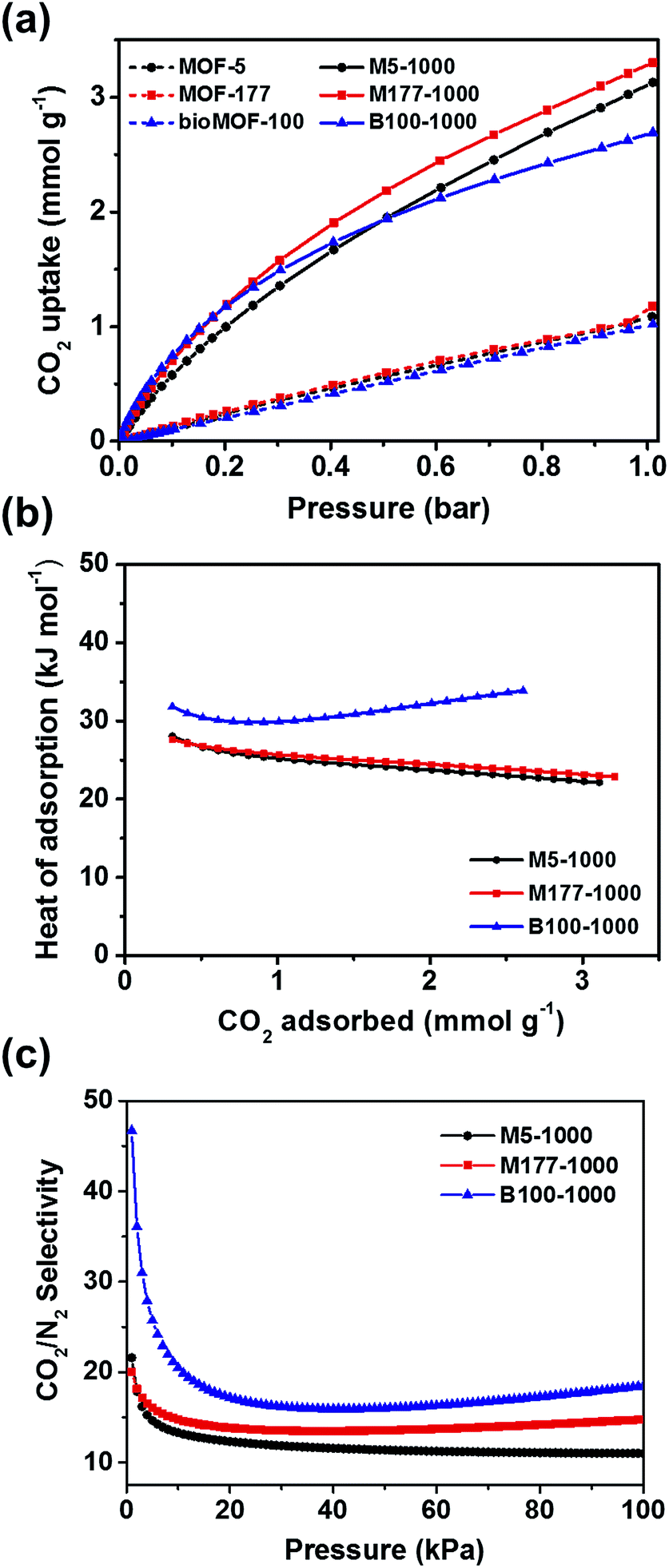 | ||
| Fig. 3 (a) CO2 adsorption isotherms of the pyrolyzed samples and parent MOFs at 298 K. (b) Isosteric heats of adsorption (Qst) of M5-1000, M177-1000, and B100-1000 for CO2. (c) CO2/N2 selectivity of M5-1000, M177-1000, and B100-1000 obtained from IAST at 298 K. | ||
Interestingly, the CO2 uptake of B100-1000 at low pressures was slightly higher than those of M177-1000 and M5-1000 (Fig. S11 and S12†), implying strong interactions between B100-1000 and adsorbed CO2 molecules. The isosteric heats of adsorption (Qst) of M5-1000, M177-1000 and B100-1000 for CO2 were calculated from the Clausius–Clapeyron equation to determine the adsorption affinity between the porous carbon materials and CO2 molecules. As depicted in Fig. 3b, B100-1000 showed higher Qst for CO2 (33.9 kJ mol−1) at near zero coverage than those of M5-1000 (28.1 kJ mol−1) and M177-1000 (27.6 kJ mol−1).
Higher CO2 uptake and Qst of B100-1000 at low pressures might result from small amounts of Lewis basic nitrogen sites in the carbon matrix which had originated from adeninate ligands in bioMOF-100. X-ray photoelectron spectroscopy (XPS) was carried out to verify the presence of Lewis basic nitrogen in the carbon surface (Fig. S5†). The atomic percentage of N in B100-1000 is 2.69%. The high resolution N 1s spectrum of B100-1000 can be deconvoluted into three peaks corresponding to pyridinic N (398.5 eV), graphitic N (401.3 eV), and N-oxide (403.3 eV) respectively (Fig. S5c†). The presence of Lewis basic pyridinic N sites for CO2 adsorption has been emphasized in the previously reported papers.23–25 Therefore, the higher affinity of B100-1000 toward CO2 in the low pressure region is attributed to the existence of Lewis basic nitrogen in the porous carbon surface.
Ideal adsorption solution theory (IAST) is normally conducted to predict the adsorptive behaviors of a two-component gas mixture from single-component isotherms.26 The IAST adsorption selectivity for CO2/N2 at 298 K was calculated for 15/85 gas mixtures. The experimental CO2 and N2 isotherms collected at 298 K for all carbon materials were fitted to the dual site Langmuir–Freundlich model. Fig. 3c and Table 1 show the IAST selectivity for CO2/N2 in the flue gas condition. B100-1000 exhibited better performance for separating CO2 from a gas mixture than other two carbon materials. Selective adsorption of CO2 from CO2/CH4 gas mixture is an important process in shale gas extraction. Thus, the IAST adsorption selectivity for CO2/CH4 at 298 K was also calculated for 50/50 gas mixtures. As depicted in Fig. S14,† M177-1000 showed slightly higher selectivity toward CO2 than other carbon materials. However, selectivity of all porous carbons for CO2/CH4 are not greatly impressive, this might result from favorable interactions between the hydrophobic carbon surface and methane gas molecules.
Since B100-1000 revealed superior CO2 uptake and separation performance in the flue gas condition, dynamic breakthrough experiments were performed to evaluate the potential of B100-1000 for the adsorptive separation of CO2/N2 mixtures. Fig. 4 shows the breakthrough curves of CO2 and N2 upon separation of a CO2/N2 mixture (CO2![[thin space (1/6-em)]](https://www.rsc.org/images/entities/char_2009.gif) :N2 = 15:85) on a column packed with B100-1000 pellets. Nitrogen elutes rapidly from the column, whereas carbon dioxide is strongly retained. This clearly shows that B100-1000 can separate CO2 and N2 under dynamic flow conditions. After performing a breakthrough experiment with a CO2/N2 mixture, the column was regenerated by purging it under a He flow of 40 ml min−1 for 30 min without heating the column. As shown in Fig. 4, essentially identical breakthrough curves were produced during the three consecutive cycles. This is remarkable because the regeneration was performed under mild conditions. In addition, since flue gases contain considerable amounts of water vapor, it was important to assess the performance of an adsorbent for CO2/N2 separation under humid conditions (RH = 50%). As displayed in Fig. 4b, almost similar breakthrough curves were obtained even in humid conditions. This indicates that this adsorbent retains CO2/N2 separation ability well under humid conditions. As such, these results demonstrate the separation potential of B100-1000 for CO2/N2 mixtures under dynamic flow conditions in the presence of water vapor.
:N2 = 15:85) on a column packed with B100-1000 pellets. Nitrogen elutes rapidly from the column, whereas carbon dioxide is strongly retained. This clearly shows that B100-1000 can separate CO2 and N2 under dynamic flow conditions. After performing a breakthrough experiment with a CO2/N2 mixture, the column was regenerated by purging it under a He flow of 40 ml min−1 for 30 min without heating the column. As shown in Fig. 4, essentially identical breakthrough curves were produced during the three consecutive cycles. This is remarkable because the regeneration was performed under mild conditions. In addition, since flue gases contain considerable amounts of water vapor, it was important to assess the performance of an adsorbent for CO2/N2 separation under humid conditions (RH = 50%). As displayed in Fig. 4b, almost similar breakthrough curves were obtained even in humid conditions. This indicates that this adsorbent retains CO2/N2 separation ability well under humid conditions. As such, these results demonstrate the separation potential of B100-1000 for CO2/N2 mixtures under dynamic flow conditions in the presence of water vapor.
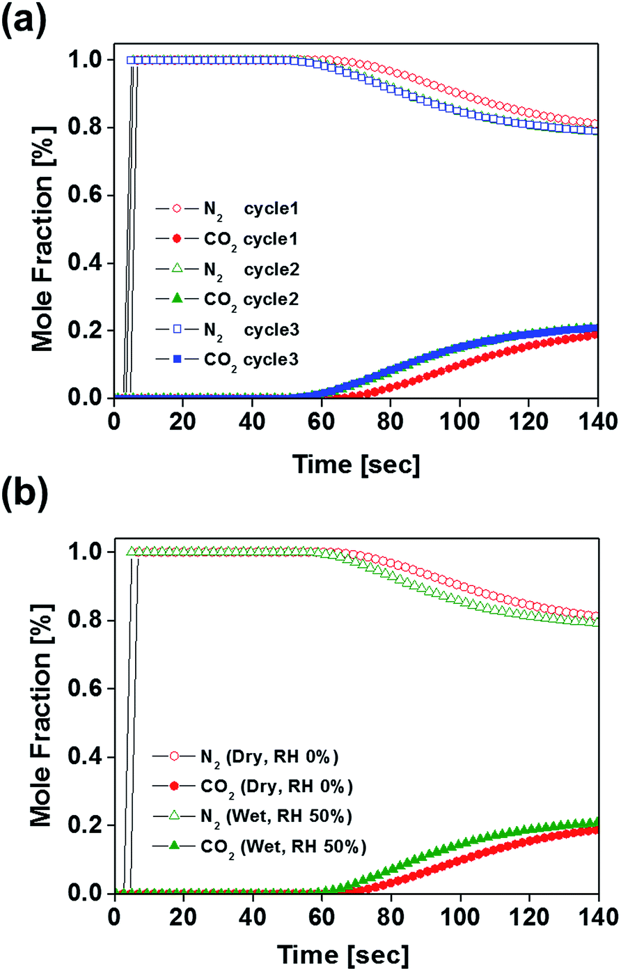 | ||
| Fig. 4 (a) Experimental breakthrough curves at three consecutive cycles for a packed-bed filled with B100-1000 with a step-input of a dry CO2/N2 mixture (CO2:N2 = 15:85, total flow rate = 40 ml min−1) at 303 K and 1 bar. (b) Breakthrough curves of CO2/N2 mixture (CO2:N2 = 15:85, total flow rate = 40 ml min−1) over B100-1000 at 303 K under dry and humid conditions (RH = 50%). | ||
Conclusions
In conclusion, porous carbon materials (M5-1000, M177-1000, and B100-1000) were prepared by simple pyrolysis of pristine MOFs (MOF-5, MOF-177, and bioMOF-100). The pyrolysis step led to the shrunken pore size of these materials and provided a suitable confined-space for CO2 uptake. Consequently, all carbon materials revealed a remarkable enhancement of CO2 uptake capacities compared to their parent MOFs. Among the carbon materials, N-doped porous carbon, B100-1000, exhibited a better adsorption capacity and selectivity for CO2 than other materials in the low pressure region. The existence of the Lewis basic nitrogen is responsible for the improved CO2 uptake. Dynamic breakthrough experiments with B100-1000 showed that B100-1000 can separate CO2 and N2 under dynamic flow conditions. Moreover, the separation ability of B100-1000 was retained even under humid condition during the three consecutive cycles. MOF-derived porous carbons, which have narrow-sized micro-pores and Lewis basic sites, can be an excellent adsorbent for post combustion CO2 capture process. We fully expect to see that other zinc and nitrogen-containing MOFs may be suitable precursors for preparing porous carbon adsorbents, and this strategy will be tested in the near future.Acknowledgements
This research was supported by the mid-career researcher program through the National Research Foundation of Korea funded by the Ministry of Science, ICT & Future Planning (NRF-2016R1A2B4010376). This work was also supported by the National Research Foundation of Korea under Grant (NRF-2016R1A2B4014256). This work was supported by the Seoul National University Research Grant.Notes and references
- E. J. Granite and H. W. Pennline, Ind. Eng. Chem. Res., 2002, 41, 5470–5476 CrossRef CAS.
- Y. Wang and M. D. LeVan, J. Chem. Eng. Data, 2009, 54, 2839–2844 CrossRef CAS.
- M. G. Plaza, S. García, F. Rubiera, J. J. Pis and C. Pevida, Chem. Eng. J., 2010, 163, 41–47 CrossRef CAS.
- J.-X. Jiang, F. Su, A. Trewin, C. D. Wood, N. L. Campbell, H. Niu, C. Dickinson, A. Y. Ganin, M. J. Rosseinsky, Y. Z. Khimyak and A. I. Cooper, Angew. Chem., Int. Ed., 2007, 46, 8574–8578 CrossRef CAS PubMed.
- X. Xu, C. Song, J. M. Andrésen, B. G. Miller and A. W. Scaroni, Microporous Mesoporous Mater., 2003, 62, 29–45 CrossRef CAS.
- J. C. Hicks, J. H. Drese, D. J. Fauth, M. L. Gray, G. Qi and C. W. Jones, J. Am. Chem. Soc., 2008, 130, 2902–2903 CrossRef CAS PubMed.
- S. R. Caskey, A. G. Wong-Foy and A. J. Matzger, J. Am. Chem. Soc., 2008, 130, 10870–10871 CrossRef CAS PubMed.
- K. A. Cychosz and A. J. Matzger, Langmuir, 2010, 26, 17198–17202 CrossRef CAS PubMed.
- N. Ding, H. Li, X. Feng, Q. Wang, S. Wang, L. Ma, J. Zhou and B. Wang, J. Am. Chem. Soc., 2016, 138, 10100–10103 CrossRef CAS PubMed.
- S.-L. Li and Q. Xu, Energy Environ. Sci., 2013, 6, 1656–1683 CAS.
- G. Srinivas, V. Krungleviciute, Z.-X. Guo and T. Yildirim, Energy Environ. Sci., 2014, 7, 335–342 CAS.
- Q. Wang, W. Xia, W. Guo, L. An, D. Xia and R. Zou, Chem.–Asian J., 2013, 8, 1879–1885 CrossRef CAS PubMed.
- H.-L. Jiang, B. Liu, Y.-Q. Lan, K. Kuratani, T. Akita, H. Shioyama, F. Zong and Q. Xu, J. Am. Chem. Soc., 2011, 133, 11854–11857 CrossRef CAS PubMed.
- Y. Shen and J. Bai, Chem. Commun., 2010, 46, 1308–1310 RSC.
- A. Aijaz, N. Fujiwara and Q. Xu, J. Am. Chem. Soc., 2014, 136, 6790–6793 CrossRef CAS PubMed.
- R. Li, X. Ren, X. Feng, X. Li, C. Hu and B. Wang, Chem. Commun., 2014, 50, 6894–6897 RSC.
- H. K. Chae, D. Y. Siberio-Perez, J. Kim, Y. Go, M. Eddaoudi, A. J. Matzger, M. O'Keeffe and O. M. Yaghi, Nature, 2004, 427, 523–527 CrossRef CAS PubMed.
- J. An, O. K. Farha, J. T. Hupp, E. Pohl, J. I. Yeh and N. L. Rosi, Nat. Commun., 2012, 3, 604 CrossRef PubMed.
- S. Lim, K. Suh, Y. Kim, M. Yoon, H. Park, D. N. Dybtsev and K. Kim, Chem. Commun., 2012, 48, 7447–7449 RSC.
- P. Nugent, Y. Belmabkhout, S. D. Burd, A. J. Cairns, R. Luebke, K. Forrest, T. Pham, S. Ma, B. Space, L. Wojtas, M. Eddaoudi and M. J. Zaworotko, Nature, 2013, 495, 80–84 CrossRef CAS PubMed.
- Y. Zhang, B. Li, K. Williams, W.-Y. Gao and S. Ma, Chem. Commun., 2013, 49, 10269–10271 RSC.
- Y. Zhao, X. Liu and Y. Han, RSC Adv., 2015, 5, 30310–30330 RSC.
- W. Xing, C. Liu, Z. Zhou, L. Zhang, J. Zhou, S. Zhuo, Z. Yan, H. Gao, G. Wang and S. Z. Qiao, Energy Environ. Sci., 2012, 5, 7323–7327 CAS.
- L. Li, Y. Wang, X. Gu, Q. Yang and X. Zhao, Chem.–Asian J., 2016, 11, 1913–1920 CrossRef CAS PubMed.
- Y. Chen and J. Jiang, ChemSusChem, 2010, 3, 982–988 CrossRef CAS PubMed.
- A. L. Myers and J. M. Prausnitz, AIChE J., 1965, 11, 121–127 CrossRef CAS.
Footnote |
| † Electronic supplementary information (ESI) available. See DOI: 10.1039/c6ra26824b |
| This journal is © The Royal Society of Chemistry 2017 |