 Open Access Article
A benzoxazine surfactant exchange for atomic force microscopy characterization of two dimensional materials exfoliated in aqueous surfactant solutions†
Tao Wang *ab,
Matthew D. J. Quinnc and
Shannon M. Notley
 *c
*c
aDepartment of Chemistry and Biotechnology, Faculty of Engineering, Science and Technology, Swinburne University of Technology, Hawthorn, VIC 3122, Australia. E-mail: wangt0715@ustc.edu.cn
bSchool of Materials Science and Engineering, Nanchang University, Nanchang, Jiangxi 330031, China
cDepartment of Applied Mathematics, Research School of Physics and Engineering, The Australian National University, Canberra, ACT 2601, Australia. E-mail: shannon.notley@anu.edu.au
First published on 13th January 2017
Abstract
Liquid-phase exfoliation of two dimensional (2D) materials in aqueous solutions with stabilization via surfactants or polymers shows great potential for large scale production and integration into a breadth of applications. Atomic force microscopy (AFM) is able to characterize thickness and the distribution of exfoliated 2D flakes, while often encountering difficulty because of re-aggregation during sample preparation. Herein, we report a surfactant exchange method with a benzoxazine surfactant for AFM sample preparation. Stable dispersions of 2D materials in chloroform could be obtained by switching a range of commonly used surfactants to this benzoxazine surfactant. The Langmuir–Blodgett method was used and flakes were kept intact with polydispersity of thickness. This method was utilized successfully on graphene as well as boron nitride and MoS2, and shows feasibility on other 2D materials.
Two dimensional (2D) materials are attracting a lot of attention from researchers due to their extraordinary properties.1–7 For example, electron mobility, intrinsic material strength and thermal conductivity allow potential applications for graphene in electronic and energy storage devices, as well as nanocomposites.2,8,9 Transition metal dichalcogenides, such as molybdenum disulphide (MoS2), are semiconducting and show significant potential for use as electronic devices and in catalytic purposes.5,10,11 Top-down and bottom-up methods have been exploited to produce 2D materials including chemical vapor deposition (CVD), micromechanical cleavage and liquid-phase exfoliation (LPE).7,12 Taking graphene as an example, through aggressive oxidation of graphite, graphene oxide (GO) is obtained by introducing carboxyl and hydroxyl groups as well as the epoxy groups.13 In spite of the high yield and great chemical viability of GO in many applications, developing large scale methods which can produce pristine graphene sheets is still crucial for the applications and technologies of graphene materials by avoiding the introduction of basal plane defects.14–18 This is also a key challenge to overcome for widespread use of other 2D materials. LPE in aqueous solutions via the aid of shear force has significant economic and environmental benefits in comparison to other manufacturing methods of 2D materials.18,19 Different types of stabilizers along with other production parameters have been optimized to achieve high yield exfoliation and highly concentrated dispersions of 2D materials in water.14,20,21
The level of exfoliation of the 2D flakes described by the number of layers is commonly regarded as the key criterion for successful production of 2D materials of the corresponding bulk solids. Atomic force microscopy (AFM) can be utilized to characterize the flakes thickness and distributions, by depositing 2D flakes onto smooth surfaces such as silica wafer or mica. Various methods have been used for the deposition step, such as dip coating,22 drop coating,23 spin coating,24 as well as a fast solvent evaporation on high temperature substrates.14 Nevertheless, these methods result in scattered and hence difficult to find particles because of the use of overly diluted dispersions making a truly statistical analysis of flake dimension difficult. In addition, an inevitable issue is the re-aggregation of 2D flakes during deposition on the solid substrate leading to great difficulty for AFM characterization and uncertainty in the true state of exfoliation.14 During the evaporation of solvent, the surface tension changes to an unfavorable region for stabilizing 2D flakes with capillary action drawing the particles together.25 The Langmuir–Blodgett (LB) method is an alternative that has been used to fabricate AFM samples suitable for imaging GO or graphene produced in organic solvents.9,10,15,16,26 The re-aggregation of graphene could be effectively avoided by confining flakes on the water surface. A volatile spreading solvent that is immiscible with water such as chloroform, dichloromethane or toluene is essential in order to spread 2D flakes on a water surface in the LB method. Nevertheless, 2D flakes that are originally produced in aqueous surfactant solutions are not usually well maintained in the exfoliated state when extracted or redispersed into those solvents.
Different surfactants have been exploited to assist 2D materials exfoliation for specific use in varied applications. For example, Pluronic® surfactants were used to produce graphene with high concentration and could be used for hydrogel preparation of graphene or thin film depositions.22,27–29 Tween 20 could be used to stabilize graphene for preparing biocompatible graphene paper material.30 Different ionic surfactants were found having different effects on transporting of graphene through porous media.31 Recently, a benzoxazine surfactant (BM1000, synthesis and structure are shown in Scheme S1, ESI†) was developed that is cheap and easy to synthesize, to exfoliate graphene in water and to fabricate freestanding graphene films with excellent electrical and mechanical strength.32 Subsequently it was demonstrated that this benzoxazine surfactant not only stabilizes graphene sheets in water but allows the flakes to be easily extracted into chloroform while maintaining the exfoliated state (transmission electron microscope (TEM) images in Fig. S1† show no obvious change before and after extraction for more than one month of storage). Furthermore, BM1000 can be simply exchanged with other surfactants used in the production of 2D materials in aqueous solution allowing straight forward extraction into chloroform. This opens the possibility to use LB techniques to characterize liquid phase exfoliated 2D materials using AFM imaging on a statistically relevant scale.
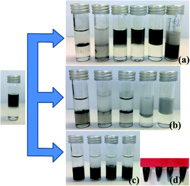
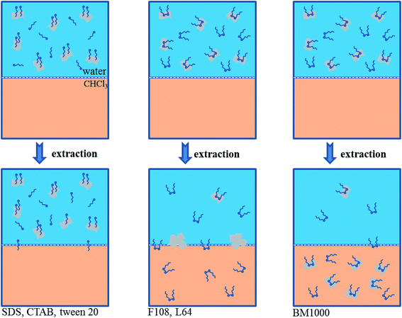
In this work, six different surfactants (BM1000, Pluronic® surfactant F108 and L64, Tween 20, cetyl trimethylammonium bromide (CTAB) and sodium dodecylsulfate (SDS); structures are shown in Scheme S2†) were used as stabilizers in the production of 2D materials through liquid phase exfoliation. The ability to extract these surfactant stabilized 2D materials into chloroform was then investigated. When mixed and shaken with chloroform, the graphene sheets with the non-ionic block co-polymeric F108 and L64 surfactants aggregated together on the water–chloroform interface but not into the chloroform phase. The graphene sheets produced with Tween 20, CTAB or SDS remain completely in the aqueous layer presumably due to the relatively highly hydrophilic nature of the surfactants. Only graphene sheets produced with BM1000 as the stabilizer could be directly extracted into chloroform layer (Fig. 1a). The nonionic surfactant of F108 and L64 are somewhat soluble in chloroform. Extracting the aqueous graphene suspension with chloroform results in the partitioning of some surfactant molecule into the organic layer. This leads to a reduction in the amount of surfactant available to stabilize the graphene sheets in the aqueous layer.33 In organic layer, hydrophobic force between surfactant and graphene layer is offset. That is, neither in water nor in chloroform graphene flakes could be stabilized. As a result, graphene sheets aggregated together to form precipitates.33 However with BM1000, surfactant molecules will also be distributed into chloroform with the π–π interactions between graphene sheets and BM1000 assisting to stabilize graphene sheets.24,34 This mechanism is illustrated in Scheme 1.
It is known that there exists a dynamic equilibrium for the adsorption of surfactants. That is, there is a regular exchange of molecules from the solution to the interface and vice versa, however the time averaged adsorbed amount is constant. Hence there is the possibility to exchange one adsorbing species with another through simple addition to the aqueous solution. This concept was explored here to investigate whether 2D materials produced using different surfactants could be exchanged with BM1000 in order to extract particles into chloroform. In the cases of the ionic surfactants CTAB and SDS, after simply adding BM1000 into these two dispersions, graphene sheets still remain in the aqueous layer. In the cases of F108, L64 and Tween 20, after simply adding BM1000 into these three dispersions, some graphene sheets could be transferred to chloroform while most of graphene sheets still remain aggregated at the water–chloroform interface (Fig. 1b). Given that under some conditions the 2D materials could be extracted to chloroform through surfactant exchange by adding BM1000, albeit with low efficiency, suggesting that a modified approach could show potential.
Another method for the extraction of the 2D materials into chloroform after extensive surfactant exchange based on high speed centrifugation showed greater success. For dispersions with F108, L64, Tween 20 and SDS, after surfactant exchange to BM1000 using high speed centrifugation (procedure is detailed in Experimental section), graphene sheets could be effectively extracted to chloroform with stable dispersions achieved (Fig. 1c and d). However this surfactant exchange procedure always resulted in flocculation for the graphene–CTAB dispersion (Fig. S2a†). The possible reason could be the reduced repulsive barrier between CTAB stabilized graphene flakes during the surfactant exchange.35 The surface potential of graphene stabilized with CTAB is positive due to adsorption of the cationic surfactant (around +50 mV),36 while for nonionic surfactants of BM1000 this value is negative (around −30 mV).32 During the surfactant exchange process graphene sheets may re-aggregate together when the surface charge decreases from a high positive value to near electrical neutrality where there is negligible steric effect.33 This suggests that this surfactant exchange method for 2D flakes is not suitable for cationic surfactants.
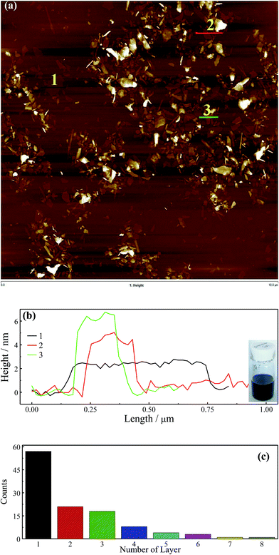
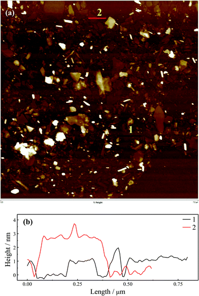
A LB method in principle could be used to prepare samples for AFM characterization due to the dispersibility of graphene with BM1000 in chloroform. Firstly, graphene with a typical anionic surfactant of SDS was studied. After surfactant exchange with BM1000 using high speed centrifugation and freeze drying, a stable graphene dispersion was obtained with chloroform as the solvent (inset, Fig. 2b). Here freeze dried samples were used instead of the transferred flakes to eliminate effects of emulsification (Fig. 1a and S2b†) and the mild aggregation on water–chloroform interface on AFM imaging. Similar Raman spectra in Fig. S3† confirm that graphene flakes were kept in their highly exfoliated state after surfactant exchange and redispersed in chloroform. Freeze dried graphene sheets stabilized with other five surfactants could not be redispersed in chloroform without surfactant exchange procedure to BM1000. A typical AFM image is shown in Fig. 2a with a scan area of 10 μm × 10 μm. A polydispersity of thickness of graphene sheet was well exhibited, except some features with significant thickness that could be the unexfoliated particles or small aggregates formed during the surfactant exchange or LB processes. The thinnest sheets with a ∼2 nm thickness were found, and by cross-sectional analyses the ascending step of thickness was found ∼2 nm either (Fig. 2b) that is consistent with previous reports.14,37 In addition, through cross-sectional analyses on several incompletely exfoliated graphene flakes (Fig. S4a and b†), an ascending step of thickness of 2 nm was confirmed. Although 2 nm is much larger than the theoretical thickness of 0.335 nm,38 graphene sheets with AFM height of around 2 nm could be reasonably regarded as monolayer, while 4 nm as bilayer and 6 nm as the triple layer (Fig. 2b),14 where the adsorbed surfactant and trapped solvent should contribute to the redundant thickness.14,39 Noteworthily, the apparent thickness of exfoliated graphene on AFM could be affected by interaction difference between tip/substrate and tip/samples, as well as the scanning parameters.14,40 Flakes thicknesses in this image were analyzed (Fig. S4c†) and a histogram of the layer numbers is included in Fig. 2c. The level of exfoliation of graphene sheets could be identified with layer number smaller than 4 for most of flakes (∼85%). Subsequently, a high temperature treatment (350 °C in air in muffle furnace) was employed in an attempt to remove the solvent and surfactant, and the AFM image is shown in Fig. 3a with the cross-sectional analyses in Fig. 3b. A smallest thickness of ∼0.9 nm could be identified, which should correspond to those sheets of 2 nm before calcination. The ∼1.8 nm and ∼2.7 nm for bilayer and triple layers could be identified as well. It should be noted here after calcine the AFM scan becomes more convoluted presumably due to contamination of the cantilever from carbon residue.41
The same method was also applied for graphene samples exfoliated with F108, L64 and Tween 20. AFM images are shown in Fig. S5a, S6a and S7a† respectively. With these three nonionic surfactants, similar results to that with SDS were obtained. Graphene sheets with different thicknesses were well exhibited except some particles with significant thickness that could be the unexfoliated particles or aggregates during surfactant exchange or LB processes. Likewise, a smallest thickness of ∼2 nm and an ascending step of similar thickness (∼2 nm) could be identified from the AFM images. The cross-sectional analyses were shown in Fig. S5b, S6b and S7b† respectively, where monolayer, bilayer, triple layers or four layers sheets were shown and referred in AFM images. Samples with these three surfactants were also calcined at 350 °C in air and AFM images and cross-sectional analyses were shown Fig. S8–10† respectively. Single layer with the thickness of ∼0.9 nm could be identified as well in all of them.
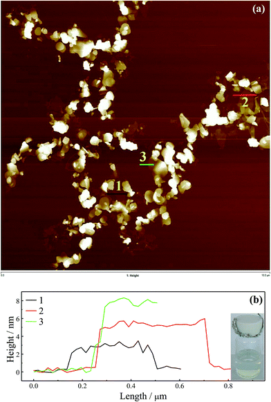
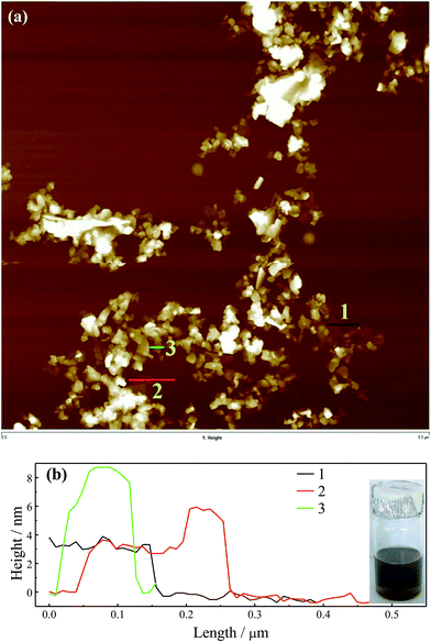
Boron nitride (BN) and MoS2 were also studied with SDS as the surfactant for exfoliation to demonstrate that this method is suitable for other types of 2D materials. Raman spectra in Fig. S11† confirm that their exfoliated state was well maintained after surfactant exchange and re-dispersed in chloroform. The AFM images and cross-sectional analyses are shown in Fig. 4 and 5. Insets show stable particle dispersions in chloroform. By the cross-sectional analyses, a smallest thickness of ∼2.5 nm for BN and ∼3.0 nm for MoS2 were found, which could be assigned to the monolayer, as well as the ascending steps with similar values to the thickness was found. These thicknesses of BN and MoS2 are consistent with previous reports, with the adsorbed surfactant and trapped solvent layer contributing to the measured values.20,21,42,43 The slightly increased thickness for MoS2 compared with BN and graphene might be attributed to the bigger monolayer thickness of MoS2 (∼0.8 nm)44 compared with BN (0.334 nm)45 and graphene (∼0.335 nm).38 The AFM images for BN and MoS2 show the imperfect exfoliation in SDS aqueous solution for these materials reflected by the many much thicker sheets. Additionally, the lack of π–π interactions between BM1000 and MoS2 and BN compared with graphene may lead to some overlaps during the LB process as shown in Fig. 4 and 5.
In summary, a simple and versatile method has been develop that could be utilized for AFM characterization of 2D materials which are exfoliated in aqueous surfactants solutions. The broad application of the method was demonstrated through surfactant exchange from several commonly used types of surfactants (including anionic surfactants and nonionic surfactants) to a type of benzoxazine surfactant. 2D materials stabilized with cationic surfactants are not suitable for this method because of the flocculation during the surfactant exchange. Furthermore, this LB method allows a future work in the preparation of transparent 2D materials films.
Experimental section
Exfoliation of 2D materials
The concentration of surfactants used depended on the chemistry and influence on the reduction in surface tension in aqueous solution. 1 mg mL−1 F108, 1 mg mL−1 L64, 1 mg mL−1 Tween 20, 0.5 mg mL−1 CTAB, 0.5 mg mL−1 SDS were used respectively. 5 mg mL−1 initial graphite flakes was used for graphene exfoliation. Typically, 200 mL graphite and surfactant solution was sonicated for 2 h at 40% amplitude. Then the suspension obtained was centrifuged at 3000g for 30 min to remove any large unexfoliated or aggregated particles. The supernatant was collected to use. BN and MoS2 were produced using the same method with SDS as the stabilizer.Surfactant exchange
High speed centrifugation of 25![[thin space (1/6-em)]](https://www.rsc.org/images/entities/char_2009.gif) 000g (Thermal Scientific sorvall rc 6+ centrifuge) was used. Firstly, the obtained dispersion was centrifuged for 2 h to receive the precipitate by removing all liquid. Then the precipitate was re-dispersed in 5 mg mL−1 BM1000 solutions by stirring and mild sonication. This centrifugation and re-dispersing process was repeated three times in order to remove the original surfactants as much as possible.
000g (Thermal Scientific sorvall rc 6+ centrifuge) was used. Firstly, the obtained dispersion was centrifuged for 2 h to receive the precipitate by removing all liquid. Then the precipitate was re-dispersed in 5 mg mL−1 BM1000 solutions by stirring and mild sonication. This centrifugation and re-dispersing process was repeated three times in order to remove the original surfactants as much as possible.
Fabrication of AFM samples
A NIMA LB trough was used. After surfactant exchange to 5 mg mL−1 BM1000, dispersions were freeze-dried and then re-dispersed in chloroform (∼0.1 mg mL−1) with the aid of mild sonication. Before using LB method, fresh chloroform was used to dilute the dispersion to a concentration around 0.01 mg mL−1. The diluted chloroform suspensions were carefully dropped on water surfaces using a glass syringe by a syringe pump (Harvard PHD2000) with a infuse speed of 6 mL min−1. Faint black colored films on water surface were formed. Then the films were compressed by LB trough barriers. The flakes were collected by vertically dipping silicon wafers into the trough and pulling them up slowly. The surfaces were dried at room temperature, followed by rinsing with water and ethanol, and blown to dry using N2 flow. Followed the initial AFM scanning, the silica wafers were calcined at 350 °C in air in a muffle furnace for 24 h to remove the surfactant or trapped solvent.AFM characterization
A Multimode 8 AFM from Bruker was used for imaging of the graphene sheets. AFM imagings were carried out in ScanAsyst-Air mode using Bruker ScanAsyst-Air probes (tip radius, 2–12 nm and silicon nitride cantilever; spring constant, 0.4 N m−1. Analyses were conducted in NanoScope Analysis software (V1.5, Bruker) and only the flatten process was used.Conflict of interest
The authors declare no competing financial interests.Acknowledgements
S. M. N. Acknowledges support from the Australian Research Council through grant FT100100177.References
- A. K. Geim and K. S. Novoselov, Nat. Mater., 2007, 6, 183–191 CrossRef CAS PubMed
.
- S. Stankovich, D. A. Dikin, G. H. Dommett, K. M. Kohlhaas, E. J. Zimney, E. A. Stach, R. D. Piner, S. T. Nguyen and R. S. Ruoff, Nature, 2006, 442, 282–286 CrossRef CAS PubMed
.
- D. Li and R. B. Kaner, Science, 2008, 320, 1170–1171 CrossRef CAS PubMed
.
- H. Chen, M. B. Muller, K. J. Gilmore, G. G. Wallace and D. Li, Adv. Mater., 2008, 20, 3557–3561 CrossRef CAS
.
- V. Nicolosi, M. Chhowalla, M. G. Kanatzidis, M. S. Strano and J. N. Coleman, Science, 2013, 340, 1226419 CrossRef
.
- C. Zhi, Y. Bando, C. Tang, H. Kuwahara and D. Golberg, Adv. Mater., 2009, 21, 2889–2893 CrossRef CAS
.
- J. N. Coleman, M. Lotya, A. O'Neill, S. D. Bergin, P. J. King, U. Khan, K. Young, A. Gaucher, S. De, R. J. Smith, I. V. Shvets, S. K. Arora, G. Stanton, H. Y. Kim, K. Lee, G. T. Kim, G. S. Duesberg, T. Hallam, J. J. Boland, J. J. Wang, J. F. Donegan, J. C. Grunlan, G. Moriarty, A. Shmeliov, R. J. Nicholls, J. M. Perkins, E. M. Grieveson, K. Theuwissen, D. W. McComb, P. D. Nellist and V. Nicolosi, Science, 2011, 331, 568–571 CrossRef CAS PubMed
.
- M. F. El-Kady, V. Strong, S. Dubin and R. B. Kaner, Science, 2012, 335, 1326–1330 CrossRef CAS PubMed
.
- X. Li, G. Zhang, X. Bai, X. Sun, X. Wang, E. Wang and H. Dai, Nat. Nanotechnol., 2008, 3, 538–542 CrossRef CAS PubMed
.
- U. Halim, C. R. Zheng, Y. Chen, Z. Lin, S. Jiang, R. Cheng, Y. Huang and X. Duan, Nat. Commun., 2013, 4, 2213–2219 Search PubMed
.
- M. D. J. Quinn, N. H. Ho and S. M. Notley, ACS Appl. Mater. Interfaces, 2013, 5, 12751–12756 CAS
.
- T. Kuilla, S. Bhadra, D. Yao, N. H. Kim, S. Bose and J. H. Lee, Prog. Polym. Sci., 2010, 35, 1350–1375 CrossRef CAS
.
- S. Stankovich, D. A. Dikin, R. D. Piner, K. A. Kohlhaas, A. Kleinhammes, Y. Jia, Y. Wu, S. T. Nguyen and R. S. Ruoff, Carbon, 2007, 45, 1558–1565 CrossRef CAS
.
- K. R. Paton, E. Varrla, C. Backes, R. J. Smith, U. Khan, A. O'Neill, C. Boland, M. Lotya, O. M. Istrate, P. King, T. Higgins, S. Barwich, P. May, P. Puczkarski, I. Ahmed, M. Moebius, H. Pettersson, E. Long, J. Coelho, S. E. O'Brien, E. K. McGuire, B. M. Sanchez, G. S. Duesberg, N. McEvoy, T. J. Pennycook, C. Downing, A. Crossley, V. Nicolosi and J. N. Coleman, Nat. Mater., 2014, 13, 624–630 CrossRef CAS PubMed
.
- K. Parvez, R. J. Li, S. R. Puniredd, Y. Hernandez, F. Hinkel, S. H. Wang, X. L. Feng and K. Mullen, ACS Nano, 2013, 7, 3598–3606 CrossRef CAS PubMed
.
- K. Parvez, Z. S. Wu, R. Li, X. Liu, R. Graf, X. Feng and K. Mullen, J. Am. Chem. Soc., 2014, 136, 6083–6091 CrossRef CAS PubMed
.
- S. De, P. J. King, M. Lotya, A. O'Neill, E. M. Doherty, Y. Hernandez, G. S. Duesberg and J. N. Coleman, Small, 2010, 6, 458–464 CrossRef CAS PubMed
.
- M. Lotya, Y. Hernandez, P. J. King, R. J. Smith, V. Nicolosi, L. S. Karlsson, F. M. Blighe, S. De, Z. Wang, I. T. McGovern, G. S. Duesberg and J. N. Coleman, J. Am. Chem. Soc., 2009, 131, 3611–3620 CrossRef CAS PubMed
.
- M. Lotya, P. J. King, U. Khan, S. De and J. N. Coleman, ACS Nano, 2010, 4, 3155–3162 CrossRef CAS PubMed
.
- K.-G. Zhou, N.-N. Mao, H.-X. Wang, Y. Peng and H.-L. Zhang, Angew. Chem., Int. Ed., 2011, 50, 10839–10842 CrossRef CAS PubMed
.
- X. Fan, P. Xu, Y. C. Li, D. Zhou, Y. Sun, M. A. Nguyen, M. Terrones and T. E. Mallouk, J. Am. Chem. Soc., 2016, 138, 5143–5149 CrossRef CAS PubMed
.
- L. Guardia, M. J. Fernandez-Merino, J. I. Paredes, P. Solis-Fernandez, S. Villar-Rodil, A. Martinez-Alonso and J. M. D. Tascon, Carbon, 2011, 49, 1653–1662 CrossRef CAS
.
- W. C. Du, J. Lu, P. P. Sun, Y. Y. Zhu and X. Q. Jiang, Chem. Phys. Lett., 2013, 568, 198–201 CrossRef
.
- S. Sampath, A. N. Basuray, K. J. Hartlieb, T. Aytun, S. I. Stupp and J. F. Stoddart, Adv. Mater., 2013, 25, 2740–2745 CrossRef CAS PubMed
.
- P. J. Yunker, T. Still, M. A. Lohr and A. G. Yodh, Nature, 2011, 476, 308–311 CrossRef CAS PubMed
.
- L. J. Cote, F. Kim and J. Huang, J. Am. Chem. Soc., 2009, 131, 1043–1049 CrossRef CAS PubMed
.
- S. M. Notley, Langmuir, 2012, 28, 14110–14113 CrossRef CAS PubMed
.
- A. Y. W. Sham and S. M. Notley, J. Colloid Interface Sci., 2015, 456, 32–41 CrossRef CAS PubMed
.
- N. Vucaj, M. D. J. Quinn, C. Baechler, S. M. Notley, P. Cottis, P. Hojati-Talemi, M. V. Fabretto, G. G. Wallace, P. J. Murphy and D. R. Evans, Chem. Mater., 2014, 26, 4207–4213 CrossRef CAS
.
- S. Park, N. Mohanty, J. W. Suk, A. Nagaraja, J. An, R. D. Piner, W. Cai, D. R. Dreyer, V. Berry and R. S. Ruoff, Adv. Mater., 2010, 22, 1736–1740 CrossRef CAS PubMed
.
- L. Liu, B. Gao, L. Wu, Y. Sun and Z. Zhou, Chem. Eng. J., 2015, 262, 1187–1191 CrossRef CAS
.
- T. Wang, M. D. J. Quinn, S. H. T. Nguyen, A. Yu and S. M. Notley, Adv. Mater. Interfaces, 2016, 3, 1600182 CrossRef
.
- Y. Liang, D. Wu, X. Feng and K. Müllen, Adv. Mater., 2009, 21, 1679–1683 CrossRef CAS
.
- M. S. Kang, K. T. Kim, J. U. Lee and W. H. Jo, J. Mater. Chem. C, 2013, 1, 1870 RSC
.
- A. Griffith and S. M. Notley, J. Colloid Interface Sci., 2012, 369, 210–215 CrossRef CAS PubMed
.
- R. J. Smith, M. Lotya and J. N. Coleman, New J. Phys., 2010, 12, 125008 CrossRef
.
- S. Wang, M. Yi, Z. Shen, X. Zhang and S. Ma, RSC Adv., 2014, 4, 25374 RSC
.
- Z. H. Ni, H. M. Wang, J. Kasim, H. M. Fan, T. Yu, Y. H. Wu, Y. P. Feng and Z. X. Shen, Nano Lett., 2007, 7, 2758–2763 CrossRef CAS PubMed
.
- O. Ochedowski, B. K. Bussmann and M. Schleberger, Sci. Rep., 2014, 4, 6003 CAS
.
- P. Nemes-Incze, Z. Osváth, K. Kamarás and L. P. Biró, Carbon, 2008, 46, 1435–1442 CrossRef CAS
.
- J. Hong, M. K. Park, E. J. Lee, D. Lee, D. S. Hwang and S. Ryu, Sci. Rep., 2013, 3, 2700 Search PubMed
.
- C. Backes, R. J. Smith, N. McEvoy, N. C. Berner, D. McCloskey, H. C. Nerl, A. O'Neill, P. J. King, T. Higgins, D. Hanlon, N. Scheuschner, J. Maultzsch, L. Houben, G. S. Duesberg, J. F. Donegan, V. Nicolosi and J. N. Coleman, Nat. Commun., 2014, 5, 4576 CAS
.
- L. Guardia, J. I. Paredes, R. Rozada, S. Villar-Rodil, A. Martínez-Alonso and J. M. D. Tascón, RSC Adv., 2014, 4, 14115 RSC
.
- H. Li, G. Lu, Z. Yin, Q. He, H. Li, Q. Zhang and H. Zhang, Small, 2012, 8, 682–686 CrossRef CAS PubMed
.
- R. V. Gorbachev, I. Riaz, R. R. Nair, R. Jalil, L. Britnell, B. D. Belle, E. W. Hill, K. S. Novoselov, K. Watanabe, T. Taniguchi, A. K. Geim and P. Blake, Small, 2011, 7, 465–468 CrossRef CAS PubMed
.
Footnote |
| † Electronic supplementary information (ESI) available: Additional information including structure and synthesis of BM1000, TEM images and Raman spectra of graphene before and after surfactant exchange, and the AFM images of graphene exfoliated with other types of surfactants. See DOI: 10.1039/c6ra26432h |
| This journal is © The Royal Society of Chemistry 2017 |

